ASM Metals HandBook Vol. 17 - Nondestructive Evaluation and Quality Control
Подождите немного. Документ загружается.

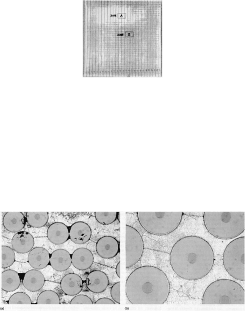
Three titanium-matrix composite panels were made available for nondestructive characterization by ultrasonic inspection,
velocity measurements, and film radiography. Only one panel showed significant anomalies, as revealed by the ultrasonic
C-scan (Fig. 25). No significant variation was seen in the velocity or x-ray inspection data.
Fig. 25 C-scan of ultrasonic signal amplitudes after transmission through a titanium-
matrix composite panel
(six plies with 0° fiber orientation). Zone A indicates a region of poor sound transmis
sion; Zone B is a region of
good sound transmission. Courtesy of Textron Specialty Materials
The panel was then sectioned parallel to the fiber lay-up, and tensile bar specimens were removed from good (zone B,
Fig. 25) and poor (zone A) sound-transmission regions. The results of tensile testing from good and bad C-scan zones
showed no correlation. This should be expected because the fiber strength dominates and because the matrix contribution
is minimal even with porosity or laminar-matrix defects.
The broken tensile specimens were then polished and photomicrographs taken from the good and bad C-scan zones.
Figure 26(a) shows the region of poor ultrasonic transmission (zone A, Fig. 25). Inadequate consolidation, porosity sites,
bunched fibers, and large grain sizes are visible throughout this zone. Specimens sectioned through the region of good
ultrasonic transmission (zone B) exhibited no porosity (Fig. 26b).
Fig. 26 Photomicrographs of specimens taken from the good and bad C-scan zones shown in Fig. 25
. (a)
Specimen from zone A. 115×. (b) Specimen from zone B. 230×
Example 2: Ultrasonic Inspection of Surface Cracks and Delamination in a
Metal-Matrix Composite Panel.
Figure 27(a) shows an ultrasonic C-scan of a titanium-matrix composite with surface cracks. This scan was performed
with a 50-MHz focused transducer at 10× magnification. Penetration of the sound was minimal because of the high
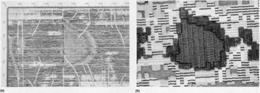
frequency being used, although there is some indication of poor consolidation (delamination) to the right of the centered
crack.
Fig. 27 Ultrasonic C-scans of a titanium-matrix composite panel with surface cracks and delamination. (a) C-
scan using a 50-MHz focused transducer at a magnification of 10×. (b) C-scan of same defect using a 10-
MHz
focused transducer
Figure 27(b) shows an ultrasonic C-scan of the same defect area produced with a 10-MHz focused transducer. The C-scan
at this frequency provided better resolution of the delaminated area, although it was found to be inadequate for
determining fiber integrity and surface cracking conditions.
Lamb Wave Testing. For the high-speed testing of a plate, strip, or wire, where the thickness is of the order of a few
wavelengths, there is considerable benefit in using Lamb waves (Ref 5). Lamb waves (or plate waves) are elastic waves
that propagate in plates of finite thickness as guided waves and are associated with particle motion in a plane normal to
the surface. As mentioned in the section "Lamb Waves" in this article, Lamb waves can be symmetrical or asymmetrical,
and they can be of different modes or mixed modes, with the velocity depending on the mode.
The present understanding of Lamb waves is based on theoretical considerations and empirical observations; the precise
particle motion involved has not been established unequivocally. However, knowledge about the phenomena associated
with Lamb waves has been developed, so that there is a sound basis for their use in nondestructive inspection.
Lamb waves are generated by the oblique incidence of an ultrasonic wave with a properly selected transmission
frequency. In addition to the common piezoelectric transducer, Lamb waves can be generated and detected with an
electromagnetic-acoustic (EMA) probe with the appropriate coil configuration (see the section "EMA Transducers" in this
article .
The most widely applied technique is to monitor the transmission along a plate between two probes with a fixed spacing.
For example, the quality of a spot or seam weld between two sheets can be monitored by the transmission along one sheet
and through the spot weld (Fig. 28). This can be done as on-line monitoring of the welding operation, but temperature
effects at the weld nugget and mode conversions at the liquid/metal interface complicate the interpretation of the results.
In wire specimens, the waves are usually known as rod waves, and there is an advantage in generating them by
magnetostriction, with a coil over the end, so that no surface contact is needed. Spirally rotating surface waves can also be
generated in a wire with a pair of probes angled to the wire axis.
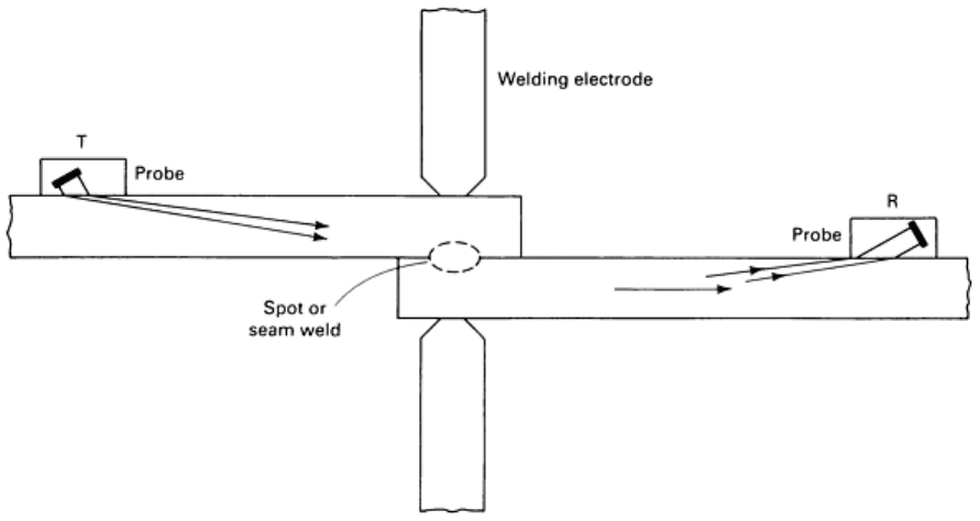
Fig. 28 Use of Lamb waves to inspect a spot-welded joint. Source: Ref 5
Leaky Lamb Wave Testing. In recent years, substantial progress has been made in the understanding of the Lamb
wave. This has resulted from the development of sophisticated theoretical and experimental techniques and the use of
powerful computing tools. It is now possible to predict and measure the response of Lamb waves even in anisotropic
layered materials, such as fiber-reinforced composites. One approach in this effort involves the use of the leaky Lamb
wave (LLW) phenomenon. Recent research indicates that this phenomenon can be used to detect and characterize defects
that would remain undetected in conventional ultrasonic techniques (Ref 6).
In LLW testing, Lamb waves are induced in a plate through a mode conversion by obliquely insonifying the plate at a
properly selected transmission frequency. If a laminate is immersed in a fluid, the Lamb waves leak energy into the fluid
at an angle that is established by Snell's law and the Lamb wave phase velocity. When an LLW is induced, the reflected
field is distorted. The specular component of the wave and the leaky wave interfere, with a phase cancellation occurring
and a null being generated between them. A schematic of LLW field behavior is shown in Fig. 29. For nondestructive
evaluation, one can monitor changes in the frequency of given LLW modes or changes in amplitude at the null zone.
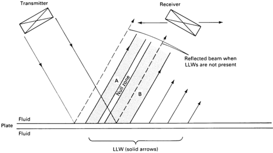
Fig. 29
Schematic of LLW phenomenon. Zone A represents the specular component, while zone B represents
the LLW component. The presence of LLWs shifts the observation of reflected energy into zone A.
A theory has been developed and corroborated regarding the behavior of LLWs in composites (Ref 7). A matrix method
solved the problem of wave propagation in multilayered anisotropic media subjected to time-harmonic (single-frequency)
or transient (pulse) disturbances. The method was applied to obtain a formal solution of the response of layered composite
plates. The solution led to stable numerical schemes for the evaluation of the displacement and stress fields within the
laminate. This analysis of LLW behavior was applied to both multiorientation laminates and bonded structures with
different interface conditions.
Leaky Lamb wave tests are performed with a pitch-catch setup and flat broadband transducers; the receiver is placed at
the null zone of the LLW field. The LLW field can be tested at various angles of incidence in the frequency range of 0.1
to 15.0 MHz using either tone bursts or pulses. For tone burst, signals with a duration sufficiently long to establish a
steady-state condition are used. The signals are either displayed as a function of time for a single frequency or as a
function of frequency in a sweep mode. For tests with short-duration pulses, the transducers are first adjusted to place the
receiver at the null zone, using the tone-burst setup. Then the transducer is substituted with a pulser-receiver, and the
signals are tested from the A-scan display. The two aspects of LLW phenomena that are commonly measured are
described below.
Reflection Field. At specific angles of incidence, the spectral response, namely, the reflected amplitude as a function of
frequency, is examined. An example of such spectra for a unidirectional graphite-epoxy laminate tested along the fibers is
shown in Fig. 30. The reflected field can also be analyzed in the time domain using pulses and commercial pulser-
receivers, with the receiving transducer placed at the null zone (Ref 6). In this case, two parameters can be used to
examine the composite laminate: the amplitude and the time-of-flight.
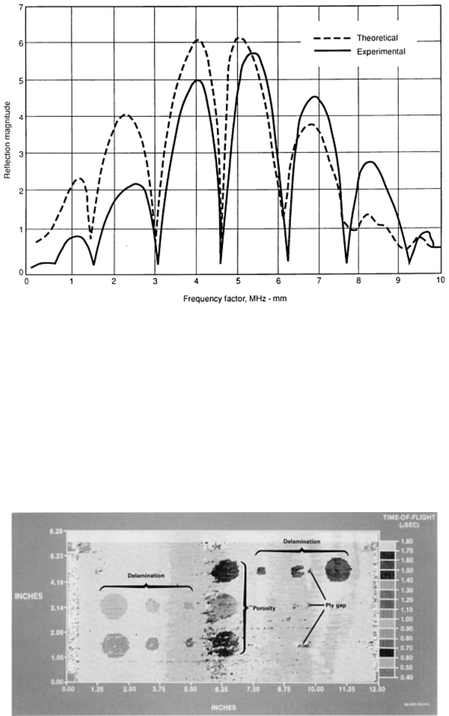
Fig. 30 Experimental and theoretical LLW spectral response of a unidirectional graphite-
epoxy laminate
obtained with a 15° angle of incidence. The x-
axis is usually expressed in frequency times thickness to
eliminate the effect of total thickness of the plate from the data.
Using amplitude measurements while C-scanning a laminate can reveal material property variations and many types of
defects. These include delaminations, ply-gap, porosity, and resin/fiber ratio changes. Further details are obtained when
using time-of-flight measurements because the depths of the discontinuities are also presented. An example of a time-of-
flight LLW C-scan is shown in Fig. 31, in which different colors were assigned to the various time-of-flight ranges to
indicate the depth of the defects in the sample. The dark lines along the C-scan image are parallel to the fiber orientation
and are a result of the migration of porosity (microballoons of 0.04 mm, or 0.0016 in., diameter) from the center of the
sample outward during the laminate cure.

Fig. 31 Pulsed LLW C-scan showing time-of-flight variations in a graphite-
epoxy laminate tested at 45° with
the fibers
Dispersion curves provide a plot of the phase velocity of Lamb waves as a function of frequency. The x-axis is usually
expressed in frequency times thickness; therefore, the effect of the total thickness of the plate is eliminated from the data.
The modes are determined from the reflected spectra by finding the frequencies at which the minima occur. By an
inversion process, one can employ the theory to determine the elastic properties of composite laminates from
experimental dispersion curves.
References cited in this section
5.
R. Halmshaw, Nondestructive Testing, Edward Arnold, 1987, p 198, 143, 211
6.
Y. Bar-Cohen and A.K. Mal, Leaky Lamb Waves Phenomena in Composites Using Pulses, in
Review of
Progress in Quantitative NDE, Vol 8, D.P. Thompson and D.E. Chimenti, Ed., Plenum Press, 1989
7.
A.K. Mal and Y. Bar-Cohen, Ultrasonic Characterization of Composite Laminates, in
Wave Propagation in
Structural Composites, Proceedings of the Joint ASME and SES meeting, AMD-
Vol 90, A.K. Mal and
T.C.T. Ting, Ed., American Society of Mechanical Engineers, 1988, p 1-16
Note cited in this section
** Examples 1 and 2 in this section were provided by Robert W. Pepper, Textron Specialty Materials.
Ultrasonic Inspection
Revised by Yoseph Bar-Cohen, Douglas Aircraft Company, McDonnell Douglas Corporation; Ajit K. Mal, University of California, Los
Angeles; and the ASM Committee on Ultrasonic Inspection
*
Electronic Equipment
Although the electronic equipment used for ultrasonic inspection can vary greatly in detail among equipment
manufacturers, all general-purpose units consist of a power supply, a pulser circuit, a search unit, a receiver-amplifier
circuit, an oscilloscope, and an electronic clock. Many systems also include electronic equipment for signal conditioning,
gating, automatic interpretation, and integration with a mechanical or electronic scanning system. Moreover, advances in
microprocessor technology have extended the data acquisition and signal-processing capabilities of ultrasonic inspection
systems.
Power Supply. Circuits that supply current for all functions of the instrument constitute the power supply, which is
usually energized by conventional 115-V or 230-V alternating current. There are, however, many types and sizes of
portable instruments for which the power is supplied by batteries contained in the unit.
Pulser Circuit. When electronically triggered, the pulser circuit generates a burst of alternating voltage. The principal
frequency of this burst, its duration, the profile of the envelope of the burst, and the burst repetition rate may be either
fixed or adjustable, depending on the flexibility of the unit.
Search Units. The transducer is the basic part of any search unit. A sending transducer is one to which the voltage burst
is applied, and it mechanically vibrates in response to the applied voltage. When appropriately coupled to an elastic
medium, the transducer thus serves to launch ultrasonic waves into the material being inspected.
A receiving transducer converts the ultrasonic waves that impinge on it into a corresponding alternating voltage. In the
pitch-catch mode, the transmitting and receiving transducers are separate units; in the pulse-echo mode, a single
transducer alternately serves both functions. The various types of search units are discussed later in this article.

Receiver-amplifier circuits electronically amplify return signals from the receiving transducer and often demodulate
or otherwise modify the signals into a form suitable for display. The output from the receiver-amplifier circuit is a signal
directly related to the intensity of the ultrasonic wave impinging on the receiving transducer. This output is fed into an
oscilloscope or other display device.
Oscilloscope. Data received are usually displayed on an oscilloscope in either video mode or radio frequency mode. In
videomode display, only peak intensities are visible on the trace; in the RF mode, it is possible to observe the waveform
of signal voltages. Some instruments have a selector switch so that the operator can choose the display mode, but others
are designed for single-mode operation only.
Clock. The electronic clock, or timer, serves as a source of logic pulses, reference voltage, and reference waveform. The
clock coordinates operation of the entire electronic system.
Signal-conditioning and gating circuits are included in many commercial ultrasonic instruments. One common
example of a signal-conditioning feature is a circuit that electronically compensates for the signal-amplitude loss caused
by attenuation of the ultrasonic pulse in the testpiece. Electronic gates, which monitor returning signals for pulses of
selected amplitudes that occur within selected time-delay ranges, provide automatic interpretation. The set point of a gate
corresponds to a flaw of a certain size that is located within a prescribed depth range. Gates are often used to trigger
alarms or to operate automatic systems that sort testpieces or identify rejectable pieces.
Image- and Data-Processing Equipment. As a result of the development of microprocessors and modern
electronics, many ultrasonic inspection systems possess substantially improved capabilities in terms of signal processing
and data acquisition. This development allows better flaw detection and evaluation (especially in composites) by
improving the acquisition of transient ultrasonic waveforms and by enhancing the display and analysis of ultrasonic data.
The development of microprocessor technology has also been useful in portable C-scan systems with hand-held
transducers (see the section "Scanning Equipment" in this article).
In an imaging system, the computer acquires the position of the transducer and the ultrasonic data from the point.
Combining the two, an image is produced on the computer monitor, either in color or in gray-scale shades; each point is
represented by a block of a predetermined size. To expedite the inspection, it is common to use large blocks. Areas that
require special attention are then inspected with a higher resolution by using smaller blocks. Built-in software in the
system allows users to analyze available information under precise, controlled conditions and enables simulation of a top
view regardless of transducer angle.
Ultrasonic Inspection
Revised by Yoseph Bar-Cohen, Douglas Aircraft Company, McDonnell Douglas Corporation; Ajit K. Mal, University of California, Los
Angeles; and the ASM Committee on Ultrasonic Inspection
*
Control Systems
Even though the nomenclature used by different instrument manufacturers may vary, certain controls are required for the
basic functions of any ultrasonic instrument. These functions include power supply, clock, pulser, receiver-amplifier, and
display. In most cases, the entire electronic assembly, including the controls, is contained in one instrument. A typical
pulse-echo instrument is shown in Fig. 32.
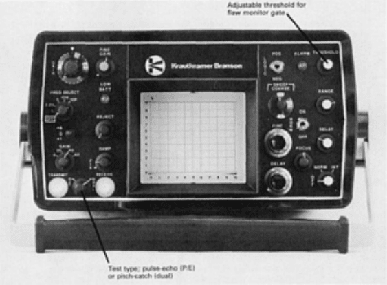
Fig. 32 Typical pulse-echo ultrasonic instrument
The power supply is usually controlled by switches and fuses. Time delays can be incorporated into the system to protect
circuit elements during warm-up. The pulses of ultrasonic energy transmitted into the testpiece are adjusted by controls
for pulse-repetition rate, pulse length, and pulse tuning. A selector for a range of operating frequencies is usually labeled
"frequency," with the available frequencies given in megahertz.
For single-transducer inspection, transmitting and receiving circuits are connected to one jack, which is connected to a
single transducer. For double-transducer inspection, such as through transmission or pitch-catch inspection, a T (transmit)
jack is provided to permit connecting one transducer for use as a transmitter, and an R (receive) jack is provided for the
use of another transducer for receiving only. A selector switch (test switch) for through (pitch-catch) or normal (pulse-
echo) transmission is provided for control of the T and R jacks.
Gain controls for the receiver-amplifier circuit usually consist of fine- and coarse-sensitivity selectors or one control
marked "sensitivity." For a clean video display, with low-level electronic noise eliminated, a reject control can be
provided.
The display (oscilloscope) controls are usually screwdriver-adjusted, with the exception of the scale illumination and
power on/off. After initial setup and calibration, the screwdriver-adjusted controls seldom require additional adjustment.
The controls and their functions for the display unit usually consist of the following:
• Controls for vertical position of the display on the oscilloscope screen
• Controls for horizontal position of display on the oscilloscope screen
• Controls for brightness of display
• Control for adjusting focus of trace on the oscilloscope screen
• Controls to correct for distortion or astigmatism that may be introduced
as the electron beam sweeps
across the oscilloscope screen
•
A control that varies the level of illumination for a measuring grid usually incorporated in the
transparent faceplate covering the oscilloscope screen
• Timing controls, which usually consist of sweep-delay and sweep-
rate controls, to provide coarse and
fine adjustments to suit the material and thickness of the testpiece. The sweep-
delay control is also used
to position the sound entry point on the left side of the display screen, with a back refl
ection or multiples
of back reflections visible on the right side of the screen
• On/off switch

In addition to those listed above, there are other controls that may or may not be provided, depending on the specific type
of instrument. These controls include the following:
•
A marker circuit, which provides regularly spaced secondary indications (often in the form of a square
wave) on or below the sweep line to serve the same purpose as scribe marks on a ruler. This circuit is
activated or left out of the di
splay by a marker switch for on/off selection. Usually there will also be a
marker-calibration or marker-adjustment control to permit selection of marker-
circuit frequency. The
higher the frequency, the closer the spacing of square waves, and the more accu
rate the measurements.
Marker circuits are controlled by timing signals triggered by the electronic clock.
Most modern
ultrasonic instruments do not have marker circuits
• A circuit to electronically compensate for a drop in the amplitude of signals reflect
ed from flaws located
deep in the testpiece. This circuit may be known as distance-amplitude correction, sensitivity-
time
control, time-corrected gain, or time-varied gain
• Damping controls that can be used to shorten the pulse duration and thus adjust the
length of the wave
packet emanating from the transducer. Resolution is improved by higher values of damping
• High-voltage or low-voltage driving current, which is selected for the transducer with a transducer-
voltage switch
• Gated alarm units, which enabl
e the use of automatic alarms when flaws are detected. This is
accomplished by setting up controllable time spans on the display that correspond to specific zones
within the testpiece. Signals appearing within the gates may automatically operate visual or
audible
alarms. These signals may also be passed on to display devices or strip-
chart recorders or to external
control devices. Gated alarm units usually have three controls: the gate-
start or delay control, which
adjusts the location of the leading edge of the gate on the oscilloscope trace; the gate-
length control,
which adjusts the length of the gate or the location of the gate trailing edge; and the alarm-
level or
sensitivity control, which establishes the minimum echo height necessary to activate an al
arm circuit. A
positive/negative logic switch determines whether the alarm is triggered above or below the threshold
level
Ultrasonic Inspection
Revised by Yoseph Bar-Cohen, Douglas Aircraft Company, McDonnell Douglas Corporation; Ajit K. Mal, University of California, Los
Angeles; and the ASM Committee on Ultrasonic Inspection
*
Transducer Elements
The generation and detection of ultrasonic waves for inspection are accomplished by means of a transducer element
acting through a couplant. The transducer element is contained within a device most often referred to as a search unit (or
sometimes as a probe). Piezoelectric elements are the most commonly used transducer in ultrasonic inspection, although
EMA transducers and magnetostriction transducers are also used.
Piezoelectric Transducers
Piezoelectricity is pressure-induced electricity; this property is characteristic of certain naturally occurring crystalline
compounds and some man-made materials. As the name piezoelectric implies, an electrical charge is developed by the
crystal when pressure is applied to it. Conversely, when an electrical field is applied, the crystal mechanically deforms
(changes shape). Piezoelectric crystals exhibit various deformation modes; thickness expansion is the principal mode used
in transducers for ultrasonic inspection.
The most common types of piezoelectric materials used for ultrasonic search units are quartz, lithium sulfate, and
polarized ceramics such as barium titanate, lead zirconate titanate, and lead metaniobate. Characteristics and applications
of these materials are summarized in Table 5.

Table 5 Characteristics and applications of transducer (piezoelectric) elements
Characteristics of piezoelectric elements
(a)
Efficiency
Suitability of element in
(a)
Coupling Contact inspection
Piezoelectric
element
Transmit
Receive
To
water
To
metal
Tolerance to
elevated
temperature
Damping
ability
Undesired
modes
(inherent
noise)
Straight-
beam
Angle-
beam
Immerse
inspection
Quartz P G G F G F G G F
G
Lithium
sulfate
F E E P P E E P F
E
Barium
titanate
G P G G P P P G G
F
Lead
zirconate
titanate
E F F E E F P E E
F
Lead
metaniobate
G F G E E E G E E G
(a)
E, excellent; G, good; F, fair; P, poor
Quartz crystals were initially the only piezoelectric elements used in commercial ultrasonic transducers. Properties of
the transducers depended largely on the direction along which the crystals were cut to make the active transducer
elements. Principal advantages of quartz-crystal transducer elements are electrical and thermal stability, insolubility in
most liquids, high mechanical strength, wear resistance, excellent uniformity, and resistance to aging. A limitation of
quartz is its comparatively low electromechanical conversion efficiency, which results in low loop gain for the system.
Lithium Sulfate. The principal advantages of lithium sulfate transducer elements are ease of obtaining optimum
acoustic damping for best resolution, optimum receiving characteristics, intermediate conversion efficiency, and
negligible mode interaction. The main disadvantages of lithium sulfate elements are fragility and a maximum service
temperature of about 75 °C (165 °F).
Polarized ceramics generally have high electromechanical conversion efficiency, which results in high loop gain and
good search-unit sensitivity. Lead zirconate titanate is mechanically rugged, has a good tolerance to moderately elevated
temperature, and does not lose polarization with age. It does have a high piezoelectric response in the radial mode, which
sometimes limits its usefulness.
Barium titanate is also mechanically rugged and has a high radial-mode response. However, its efficiency changes with
temperature, and it tends to depolarize with age, which makes barium titanate less suitable for some applications than lead
zirconate titanate.
Lead metaniobate exhibits low mechanical damping and good tolerance to temperature. Its principal limitation is a high
dielectric constant, which results in a transducer element with a high electrical capacitance.
