ASM Metals HandBook Vol. 17 - Nondestructive Evaluation and Quality Control
Подождите немного. Документ загружается.

Flaw size is most often estimated by comparing the amplitude of an echo from an interface of unknown size with the
amplitude of echoes from flat-bottom holes of different diameter in two or more reference blocks. To compensate for any
sound attenuation within the testpiece, these guidelines should be followed:
•
Reference holes should be about the same depth from the front (entry) surface of the reference block as
the flaw is from the front surface of the testpiece
• Reference blocks should be made of material with acoustic properties similar to those of the testpiece
•
The sound beam should be larger than the flaw. (This can best be determined by moving the search unit
back and forth on the surface of the part being inspected relative to
a position centered over the flaw and
observing the effect on both flaw echo and back reflection. If the search unit can be moved slightly
without affecting the height of either the flaw echo or back reflection, it can be assumed that the sound
beam is sufficiently larger than the flaw)
•
Control settings on the instrument and physical arrangement of search unit, couplant, and specimen are
the same regardless of whether the specimen is a testpiece or a reference block
In practice, a calibration curve is constructed using reference blocks, as described in the section "Determination of Area-
Amplitude and Distance-Amplitude Curves" in this article. Flaw size is then determined by reading the hole size
corresponding to the amplitude of the flaw echo directly from the calibration curve. Flaw size determined in this manner
is only an estimate of minimum size and should not be assumed equal to the actual flaw size. The amount of sound energy
reflected back to the search unit will be less than that from a flat-bottom hole of equal size if an interface has a surface
rougher than the bottom surfaces of the reference holes, is oriented at an angle other than 90° to the sound beam, is
curved, or transmits some of the sound energy rather than acting as an ideal reflector. Therefore, to produce equal echo
heights, actual flaws having any of these characteristics must be larger than the minimum size determined from the
calibration curve. This is why flaw sizes are frequently reported as being no smaller than x, where x is the flaw size that
has been estimated from the calibration curve.
It may seem logical to estimate flaw size by comparing the amplitude of a flaw echo to the amplitude of the back
reflection. Although an assumption that the ratio of flaw-echo height to back reflection amplitude is equal to the ratio of
flaw area to sound beam cross section has been used in the past, this assumption should be considered to be completely
unreliable, even when distance-amplitude corrections are applied.
Loss of Back Reflection. If a flaw is larger than a few percent of the cross section of a sound beam, the amplitude of
the back reflection is less than that of a similar region of the testpiece (or of another testpiece) that is free of flaws.
Because sound travels essentially in straight lines, the reflecting interfaces within the testpiece (flaws) cast sound shadows
on the back surface, in a manner similar to that in which opaque objects introduced into a beam of light cast shadows on a
screen. Sound shadows reduce the amount of energy reflected from the back surface by reducing the effective area of the
sound beam. The back reflection is not reduced in direct proportion to the percentage of the original sound beam
intercepted by the flaw; the exact proportion varies widely. This effect is termed loss of back reflection, regardless of
whether the back-surface signal echo is lost completely or merely reduced in amplitude.
A flaw indication is produced when an internal interface reflects sound onto the receiving transducer. A loss of back
reflection can occur even if no flaw indication appears on the A-scan display. If the sound is reflected to the side, where
the reflection cannot be picked up by the transducer, there is still a loss of back reflection because of the shadow effect.
This provides an additional means of detecting the presence of flaws. Although no direct indication shows on the
oscilloscope screen, the size of a flaw can be estimated from the percentage lost from the height of the back reflection
indication. This estimate is generally less accurate than an estimate made from an actual flaw indication. There is no
assurance that only one flaw produces a given loss of back reflection; other factors, such as excessive roughness of the
back surface or internal microporosity, can also reduce the amplitude of the back reflection.
One means of distinguishing whether a certain loss of back reflection is due to the presence of identifiable flaws is to
move the search unit back and forth about a mean position over the suspected flaw. If the back reflection rises and falls as
the search unit is moved, the presence of specific identifiable flaws can be presumed. Angle-beam techniques or other
nondestructive inspection methods can then be used for positive identification of the flaw. However, if the back reflection
remains relatively steady as the search unit is moved but the amplitude of the indication is measurably lower than the
expected or standard value, the material presumably contains many small flaws distributed over a relatively broad region.
This material condition may or may not be amenable to further study using other ultrasonic techniques or other
nondestructive methods.
Spurious indications from reflections or indications of sources other than discontinuities are always a possibility.
Reflections from edges and corners, extra reflections due to mode conversion, and multiple reflections from a single
interface often look like flaw indications. Sometimes, these false, or nonrelevant, indications can be detected by
correlation of the apparent flaw location with some physical feature of the testpiece. On other occasions, only the
experience of the operator and thorough preliminary analysis of probable flaw types and locations can separate
nonrelevant indications due to echoes from actual flaws. As a rule, any indication that remains consistent in amplitude
and appearance as the search unit is moved back and forth on the surface of the testpiece should be suspected of being a
nonrelevant indication if it can be correlated with a known reflective or geometric boundary. Nonrelevant indications are
more likely to occur in certain types of inspection--for example, in longitudinal wave inspection from one end of a long
shaft, inspection of complex-shape testpieces, inspection of parts where mixed longitudinal and shear waves may be
present, and various applications of shear wave or surface wave techniques.
There are certain other types of indications that may interfere with the interpretation of A-scan data. All electronic circuits
generate a certain amount of noise consisting of high-frequency harmonics of the main-signal frequency. Electronic noise
is generally of low amplitude and is troublesome only when the main signal is also of low amplitude. In ultrasonic
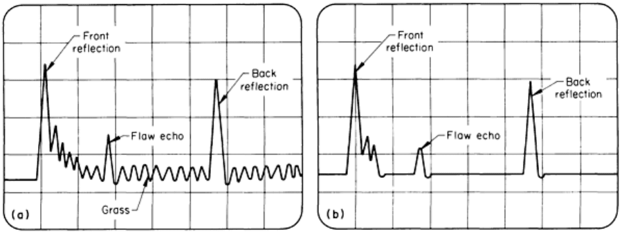
inspection, electronic noise can appear on an A-scan display as a general background, or waviness (called grass), in the
main trace at all depths (Fig. 15a). This waviness, or grass, is more pronounced at the higher gain settings. Many
instruments are equipped with reject circuits that filter out grass, although usually with some attendant loss of echo-signal
amplitude, as shown in Fig. 15(b). When reject circuits are used, they should be adjusted so that grass is reduced only
enough not to be a hindrance. If too much rejection is used, small-amplitude echoes will be suppressed along with the
grass, and there will be a loss in sensitivity of the inspection technique and the linearity of the instrument will be affected.
Fig. 15 A-scan displays showing (a) app
earance of electronic noise as waviness (grass) and (b) grass filtered
out by use of a reject circuit with some attendant loss of echo-signal amplitude
A second type of interference occurs when coarse-grain materials are inspected. Reflections from the grain boundaries of
coarse-grain materials can produce spurious indications throughout the test depth (Fig. 16). This type of interference,
called hash, is most often encountered in coarse-grain steels; it is less troublesome with fine-grain steels or nonferrous
metals. Sometimes, hash can be suppressed by adjusting the frequency and pulse length of the ultrasonic waves so that the
sound beam is less sensitive to grain-boundary interfaces.
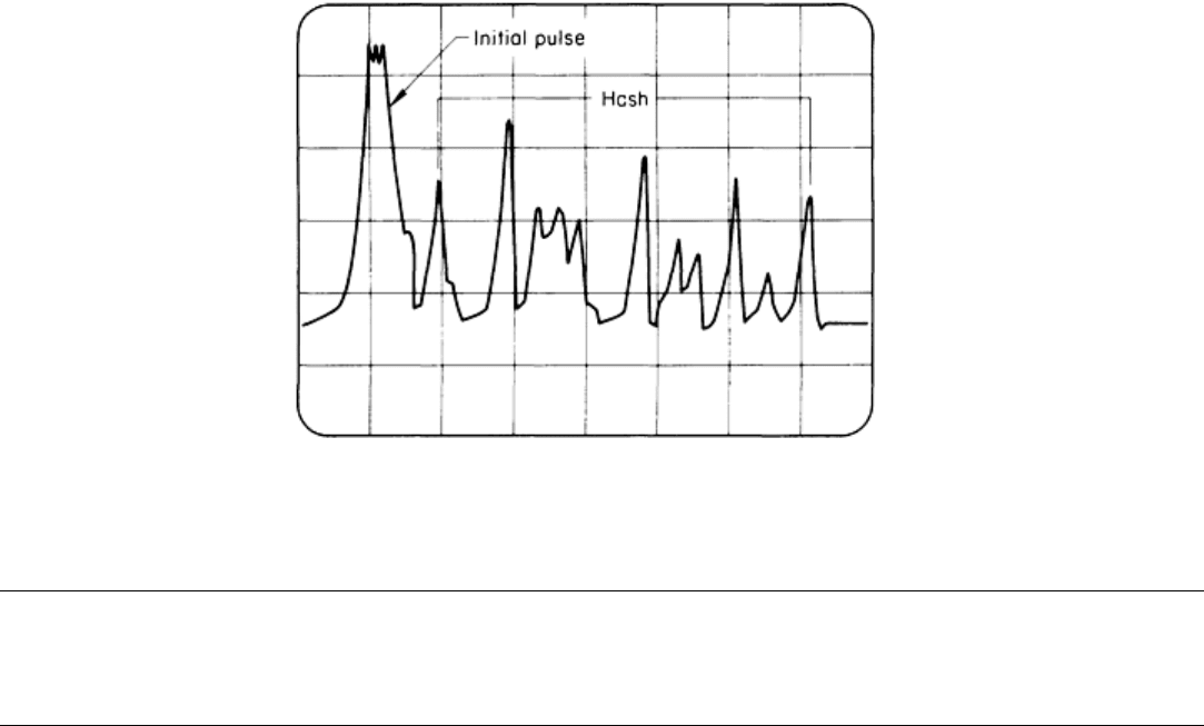
Fig. 16 A-scan display showing coarse-grain indications (hash) that interfere with detection of discontinuities
Ultrasonic Inspection
Revised by Yoseph Bar-Cohen, Douglas Aircraft Company, McDonnell Douglas Corporation; Ajit K. Mal, University of California, Los
Angeles; and the ASM Committee on Ultrasonic Inspection
*
Angle-Beam Techniques
In angle-beam techniques, the incident sound pulse enters the testpiece at an oblique angle instead of at a right angle. In
contrast with straight-beam tests, this approach eliminates echoes from the front and back surfaces and only displays
reflections from discontinuities that are normal to the incident beam. Only rarely will a back surface be oriented properly
to give a back reflection indication.
Figure 17 shows the arrangement of an angle-beam technique with a contact transducer on a pipe and a plate. The sound
beam enters the test material at an angle and propagates by successive zigzag reflections from the specimen boundaries
until it is interrupted by a discontinuity or boundary where the beam reverses direction and is reflected back to the
transducer. According to the angle selected, the wave modes produced in the test material may be mixed longitudinal and
shear, shear only, or surface modes. Usually, angle-beam testing is accomplished with shear waves, although refracted
longitudinal waves or surface waves can be used in some applications.
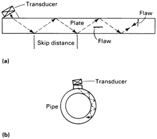
Fig. 17 Angle-beam testing with a contact transducer on a plate (a) and pipe (b)
Angle-beam techniques are used for testing welds, pipe or tubing, sheet and plate material, and specimens of irregular
shape (such as welds) where straight beams are unable to contact all of the surface. Angle-beam techniques are also useful
in flaw location when there is a loss of back reflection. In flaw location, the time base (horizontal scale) on the
oscilloscope must be carefully calibrated because in angle-beam testing there is no back reflection echo to provide a
reference for depth estimates of the flaw. Usually, an extended time base is used so that flaws are located with one or two
skip distances from the search unit (see Fig. 17 for the definition of skip distance).
Figure 17(a) shows how a shear wave from an angle-beam transducer progresses through a flat testpiece--by reflecting
from the surfaces at points called "nodes". The linear distance between two successive nodes on the same surface is called
the "skip distance" and is important in defining the path over which the transducer should be moved for reliable and
efficient scanning. The skip distance can easily be measured by using a separate receiving transducer to detect the nodes
or by using an angle-beam test block, or it can be calculated. Once the skip distance is known, the region over which the
transducer should be moved to scan can be determined.
Moving the search unit back and forth between one-half skip distance and one skip distance from an area of interest can
be used not only for the purpose of defining the location, depth, and size of a flaw but also for the general purpose of
initially detecting flaws. Figure 18 illustrates this back-and-forth movement as a way of scanning a weld for flaws.
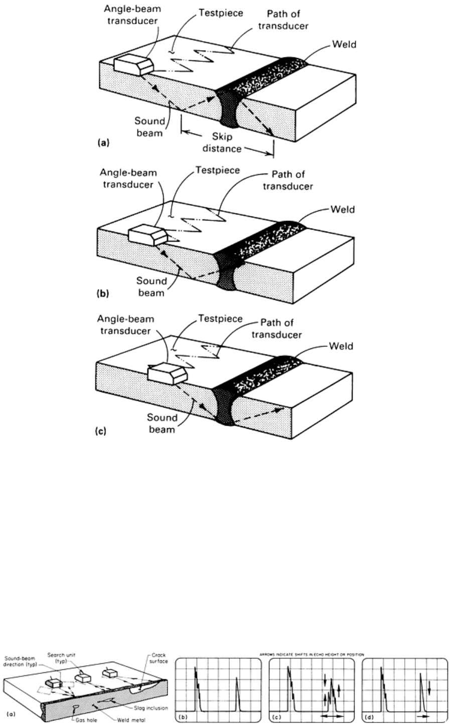
Fig. 18 Three
positions of the contact type of transducer along the zigzag scanning path used during the
manual angle-
beam ultrasonic inspection of welded joints. The movement of the sound beam path across the
weld is shown on a section taken along the centerline of the
transducer as it is moved from the far left position
in the scanning path (a), through an intermediate position (b), to the far right position (c).
Sometimes, moving the search unit in an arc about the position of a suspected flaw or swiveling the search unit about a
fixed position can be equally useful (Fig. 19a). As shown in Fig. 19(b), traversing the search unit in an arc about the
location of a gas hole produces little or no change in the echo; the indication on the oscilloscope screen remains constant
in both amplitude and position on the trace as the search unit is moved. On the other hand, if the search unit were to be
swiveled on the same spot, the indication would abruptly disappear after the search unit had been swiveled only a few
degrees.
Fig. 19 Angle-beam inspection of a weldment showing effect of search-
unit movements on oscilloscope screen
displ
ay patterns from three different types of flaws in welds. (a) Positions of search units on the testpiece. (b)
Display pattern obtained from a gas hole as the result of traversing the search unit in an arc about the location
of the flaw. (c) Display pattern
obtained from a slag inclusion as the result of swiveling the search unit on a
fixed point. (d) Display pattern obtained from a crack, using the same swiveling search-
unit movement as in
(c).
If the flaw is a slag inclusion (Fig. 19a), swiveling the search unit on the same spot causes the echo indication to vary
randomly; some peaks rise and others fall, and the position of the signal shifts in either direction on the time trace, as
indicated by arrows on the oscilloscope screen display in Fig. 19(c). Traversing the search unit in an arc would cause the
signal to vary randomly in amplitude and to broaden slightly rather than shift in position.
If the flaw is a crack (Fig. 19a), swiveling the search unit in either direction away from the direction of maximum echo
amplitude causes the peak to fall rapidly, accompanied by a slight shift to the right on the time trace, as indicated by
arrows on the display in Fig. 19(d). Traversing the search unit in an arc would cause the echo signal to broaden slightly
and fall rapidly with no change in position.
Surface Wave Technique. A special adaptation of the angle-beam technique results in the propagation of a surface
wave, as discussed in the section "Angle-Beam Units" in this article. Surface waves are mainly used for the detection of
shallow surface cracks and other similar flaws occurring at or just below the surface of the testpiece. This technique is
most effective when flaws are most likely to extend to the surface or to be located in the dead zone for other techniques.
Display appearance is similar to that for ordinary angle-beam testing; only flaw indications are displayed on an extended-
time sweep trace.
Polar backscattering is basically an angle-beam technique, in which a single transducer has an oblique incidence with
the front and back surface of a testpiece. Like other angle-beam techniques, this approach eliminates the detection of
reflections from the front and back of the testpiece and only accounts for scattering from discontinuities that are normal to
the ultrasonic pulse. In polar backscattering, however, the primary objective is to measure the amplitude of scattering as a
function of transducer orientation. Polar backscattering is a useful nondestructive evaluation method for composite
materials because their defects mostly have angle-dependent characteristics, which can be revealed by this method (Ref
3).
The test setup for polar backscattering is shown schematically in Fig. 20. Generally, fibers or discontinuities backscatter
when the polar angle is normal to their surfaces. Figure 21 shows the response from a cross-ply SiC/Ti laminate tested at
an incidence angle of 16.5°. The maxima in backscattering are observed each time the ultrasonic beam is normal to a fiber
axis. The finite width of the peaks on the angular spectrum is determined by the transducer and the fiber directivity. The
test can be performed in the frequency range of 1 to 25 MHz, using broadband pulses.
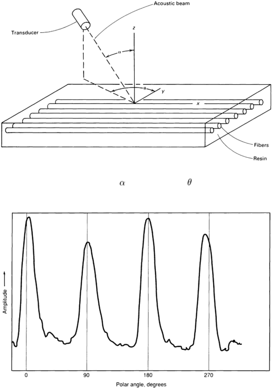
Fig. 20 Schematic of polar backscattering setup. , angle of incidence;
, polar angle (the angle between the
y-axis and the projection of the beam path on the x-y plane)
Fig. 21 Polar backscattering response from a SiC/Ti cross-ply laminate. The angle of incidence was 16.5°.
Polar backscattering can be used to detect matrix cracking because matrix cracks generate much higher backscattering
than the backscattering of the fibers (about 30 dB for graphite-epoxy). By setting a gate with a cutoff level above the
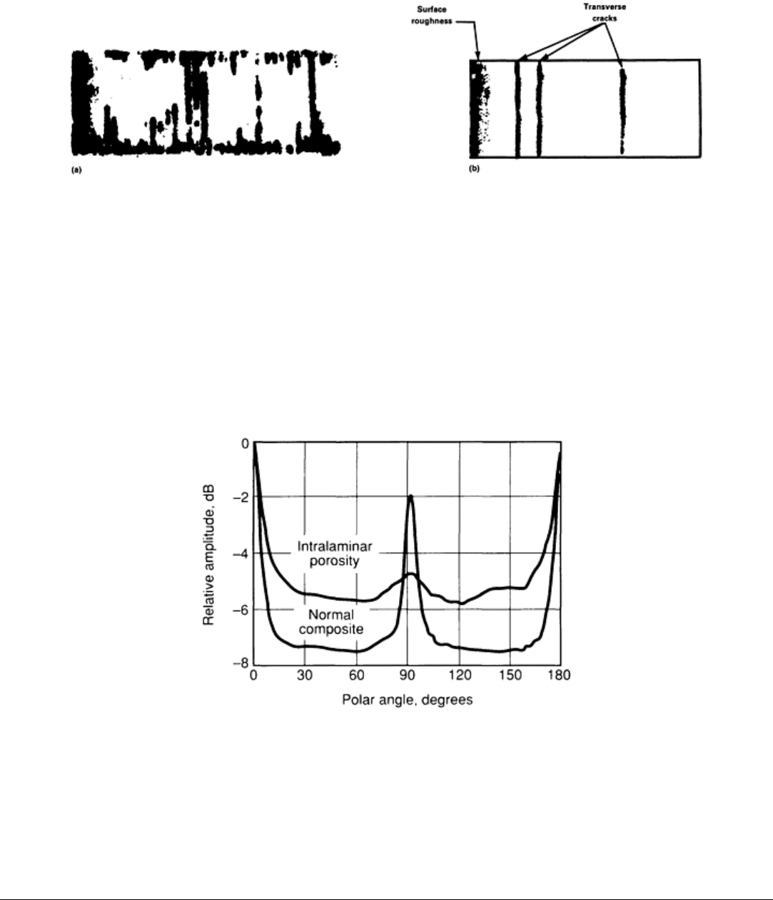
backscattering amplitude of the fibers, matrix cracking can be easily detected, as indicated in Fig. 22. This concept can
also be applied to the detection of transverse cracking in ARALL laminates, which consist of aramid-aluminum layers
(Ref 4).
Fig. 22 C-scan image of polar backscattering from transverse cracks in a graphite-epoxy laminate.
(a) Fatigued
sample. (b) Statically loaded sample
Porosity is another type of defect that can be detected by polar backscattering. Generally, porosity accumulates between
the layers of a composite laminate. Because the layers are randomly spread and have no preferred orientation, they
generate backscattering at all polar angles. This behavior of porosity is shown in Fig. 23, in which the backscattering
responses are shown for two laminates. As can be seen, porosity introduces an increase in scattering for angles that are
not normal to the fiber axis as compared to the response from a defect-free laminate. This behavior of the fibers generates
a spatial window in the backscattering through which defects of different scattering directivity can be characterized.
Fig. 23 Effect of porosity on the polar backscattering from a graphite-epoxy laminate
Backscattering can also be used to detect corrosion in various metals. This is feasible because corrosion disrupts the
surface of the tested metal (Ref 4). Pitting corrosion, as well as scale, can be very easy to detect when testing aluminum
plates at a 16° angle of incidence.
References cited in this section
3.
Y. Bar-Cohen, NDE of Fiber Reinforced Composites--A Review, Mater. Eval., Vol 44 (No. 4), 1986, p 446-
454

4.
Y. Bar-Cohen, Nondestructive Characterization of Defects Using Ultrasonic Backscattering, in
Ultrasonic
International 87, Conference Proceedings, Butterworth, 1987, p 345-352
Ultrasonic Inspection
Revised by Yoseph Bar-Cohen, Douglas Aircraft Company, McDonnell Douglas Corporation; Ajit K. Mal, University of California, Los
Angeles; and the ASM Committee on Ultrasonic Inspection
*
Transmission Methods
**
Regardless of whether transmission ultrasonic testing is done with direct beams or reflected beams, flaws are detected by
comparing the intensity of ultrasound transmitted through the testpiece with the intensity transmitted through a reference
standard made of the same material. Transmission testing requires two search units--one to transmit the ultrasonic waves
and one to receive them. Immersion techniques or water-column (bubbler or squirter) techniques (see the section "Water-
Column Designs" in this article) are most effective because they provide efficient and relatively uniform coupling
between the search units and the testpiece.
Good coupling is critical to transmission methods because variations in sound transmission through the couplants have
corresponding effects on measured intensity. These variations in measured intensity introduce errors into the test results
and frequently lead to invalid tests. For example, if go/no-go testing is being done and the criterion for rejection is a 10%
loss in transmitted intensity, variations of 10% or more in coupling efficiency can cause the rejection of flaw-free
testpieces. In addition to good coupling, accurate positioning of the search units with respect to each other is critical.
Once proper alignment of the search units is established, they should be rigidly held in position so that no variations in
measured sound intensity can result from relative movement between them. Scanning is then accomplished by moving
testpieces past the search units.
Displays of transmission test data can be either oscilloscope traces, strip chart recordings, or meter readings.
Oscilloscopes are used to record data mainly when pulsed sound beams are used for testing; strip charts and meters are
more appropriate for continuous beams. With all three types of display, alarms or automatic sorting devices can be used to
give audible warning or to shunt defective workpieces out of the normal flow of production.
Pitch-catch testing can be done either with direct beams (through transmission testing) or with reflected beams using
two transducers. The transducers may be housed in separate search units--one sending and the other receiving--or they
may be combined in a single search unit. In both instances, pulses of ultrasonic energy pass through the material, and the
intensities of the pulses are measured at the point of emergence. An oscilloscope display is triggered simultaneously with
the initial pulse, and the transmitted-pulse indication appears on the screen to the right of the initial-pulse indication in a
manner quite similar to the back reflection indication in pulse-echo testing. A major advantage of pitch-catch testing is
that disturbances and spurious indications can be separated from the transmitted pulse by their corresponding transit
times. Only the intensity of the transmitted pulse is monitored; all other sound waves reaching the receiver are ignored.
An electronic gate can be set to operate an alarm or a sorting device when the monitored intensity drops below a preset
value.
When reflected pulses are used, the technique is almost identical to the loss of back reflection technique that is often used
in ordinary pulse-echo testing. In reflected-beam transmission testing, however, no attempt is made to evaluate any signal
other than the main reflected pulse; echo signals that would be carefully interpreted in pulse-echo testing are not
considered in transmission testing.
Continuous-beam testing does not require a pulser circuit or an oscilloscope. The initial intensity is not monitored,
just the transmitted intensity. In this type of testing, considerable interference from standing waves occurs when the
ultrasound of a single frequency is introduced into a part. Usually, only a small amount of the direct beam is absorbed by
the receiver; the remainder is reflected back and forth repeatedly within the testpiece, soon filling the entire volume of
material with a spatial field of standing waves. These standing waves create interference patterns of nodes and antinodes
that alter the intensity of the direct beam. Small differences in dimensions or sound-transmission properties between two
testpieces of the same design can result in large differences in the measured sound beam intensity because of a shift in the
spatial distribution of standing waves.
Standing waves are avoided when pulsed ultrasonic beams are used. They cannot be eliminated when continuous beams
are used; however, the effect can be made relatively constant by "wobbling" the test frequency, that is, by rapidly
modulating the test frequency about the fundamental test frequency. Either periodic or aperiodic modulation can be used
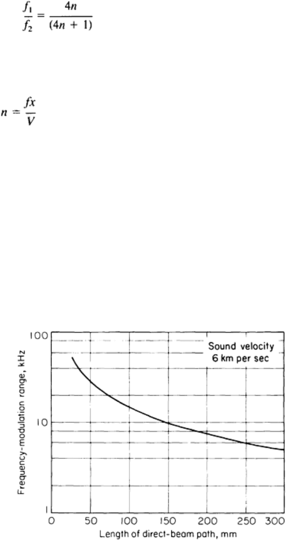
with equivalent results as long as the range of modulation is wide enough. The required range can be estimated from:
(Eq 12)
where f
1
and f
2
are the results of the frequency range and n is the number of wavelength modes in the shortest direct-beam
path from transmitter to receiver. The value of n is determined from:
(Eq 13)
where f is the fundamental frequency, x is the path length of the direct beam, and V is the velocity of the particular wave
form involved.
The frequency modulation range (f
2
- f
1
) varies with the length of the direct-beam path, as shown in Fig. 24 for a sound
wave velocity of 6 km/s (4 miles/s). When applied to the straight-beam, longitudinal wave inspection of steel plate, which
has a sound wave velocity of about 6 km/s (4 miles/s), the horizontal scale in Fig. 24 can be read directly as plate
thickness. The frequency modulation range (f
2
- f
1
) is independent of fundamental frequency, f, but when it is considered
as a percentage of the fundamental frequency, higher test frequencies require a lower percentage of modulation to average
out standing-wave effects. This is important, because some search units lose sensitivity when the operating frequency
differs from the design frequency by more than a few percent. Consequently, higher frequencies are required for the
transmission testing of thin testpieces than for thick testpieces. In some cases, equipment limitations may make it
impossible to use transmission methods on thin testpieces.
Fig. 24 Effect of direct-
beam path length on frequency modulation range needed to avoid standing waves in
the continuous-beam transmission testing of a material in which sound velocity is 6 km/s (4 miles/s).
Applications. The main application of transmission methods is the inspection of plate for cracks and laminations that
have relatively large dimensions compared to the size of the search units. The following two examples illustrate the
variation of ultrasonic transmission in the nondestructive evaluation of metal-matrix composite panels.
Example 1: Ultrasonic Inspection of Titanium-Matrix Composite Panels.
