ASM Metals HandBook Vol. 17 - Nondestructive Evaluation and Quality Control
Подождите немного. Документ загружается.

waves in a second medium. If the angle is increased, the direction of the refracted longitudinal wave will approach the
plane of the boundary (
l
90°). At some specific value of
l
,
l
will exactly equal 90°, above which the refracted
longitudinal wave will no longer propagate in the material, leaving only a refracted (mode-converted) shear wave to
propagate in the second medium. This value of
l
is known as the first critical angle. If
l
is increased beyond the first
critical angle, the direction of the refracted shear wave will approach the plane of the boundary (
t
90°). At a second
specific value of
l
,
t
will exactly equal 90°, above which the refracted transverse wave will no longer propagate in the
material. This second value of
l
is called the second critical angle.
Critical angles are of special importance in ultrasonic inspection. Values of
l
between the first and second critical angles
are required for most angle-beam inspections. Surface wave inspection is accomplished by adjusting the incident angle of
a contact-type search unit so that it is a few tenths of a degree greater than the second critical angle. At this value, the
refracted shear wave in the bulk material is replaced by a Rayleigh wave traveling along the surface of the testpiece. As
mentioned earlier in this article, Rayleigh waves can be effectively sustained only when the medium on one side of the
interface (in this case, the surface of the testpiece) is a gas. Consequently, surface wave inspection is primarily used with
contact methods.
In ordinary angle-beam inspection, it is usually desirable to have only a shear wave propagating in the test material.
Because longitudinal waves and shear waves propagate at different speeds, echo signals will be received at different
times, depending on which type of wave produced the echo. When both types are present in the test material, confusing
echo patterns may be shown on the display device, which can lead to erroneous interpretations of testpiece quality.
Frequently, it is desirable to produce shear waves in a material at an angle of 45° to the surface. In most materials,
incident angles for mode conversion to a 45° shear wave lie between the first and second critical angles. Typical values of
l
for all three of these--first critical angle, second critical angle, and incident angle for mode conversion to 45° shear
waves--are listed in Table 2 for various metals.
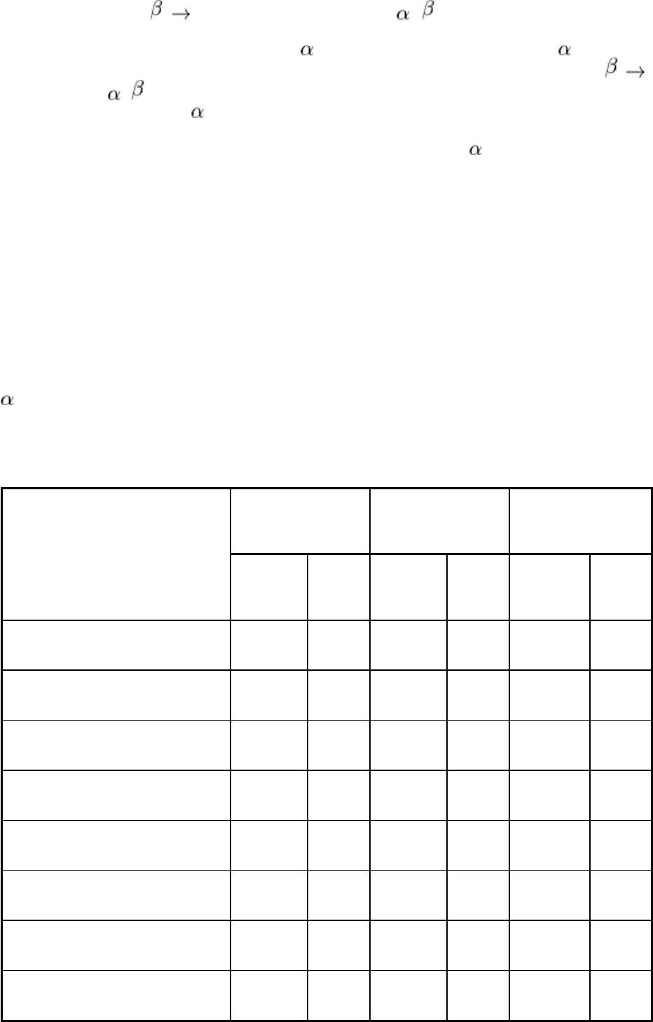
Table 2 Critical angles for immersion and contact testing, and incident angle for 45° shear wave
transmission, in various metals
First critical angle,
degrees
(a)
, for:
Second critical angle,
degrees
(a)
, for:
45° shear wave incident
angle, degrees
(a)
, for:
Metal
Immersion
testing
(b)
Contact
testing
(c)
Immersion
testing
(b)
Contact
testing
(c)
Immersion
testing
(b)
Contact
testing
(c)
Steel 14.5 26.5 27.5 55 19
35.5
Cast iron 15-25 28-50 . . . . . . . . .
. . .
Type 302 stainless steel 15 28 29 59 19.5
37
Type 410 stainless steel 11.5 21 30 63 20.5
39
Aluminum alloy 2117-T4 13.5 25 29 59.5 20
37.5
Beryllium 6.5 12 10 18 7
12.5
Copper alloy 260 (cartridge brass, 70%)
23 44 46.5 . . . 31
67
Inconel 11 20 30 62 20.5
38.5

Magnesium alloy M1A 15 27.5 29 59.5 20
37.5
Monel 16.5 30 33 79 23
44
Titanium 14 26 29 59 20 37
(a)
Measured from a direction normal to surface of test material.
(b)
In water at 4 °C (39 °F).
(c)
Using angle block (wedge) made of acrylic plastic
Beam Intensity. The intensity of an ultrasonic beam is related to the amplitude of particle vibrations. Acoustic
pressure (sound pressure) is the term most often used to denote the amplitude of alternating stresses exerted on a material
by a propagating ultrasonic wave. Acoustic pressure is directly proportional to the product of acoustic impedance and
amplitude of particle motion. The acoustic pressure exerted by a given particle varies in the same direction and with the
same frequency as the position of that particle changes with time. Acoustic pressure is the most important property of an
ultrasonic wave, and its square determines the amount of energy (acoustic power) in the wave. It should be noted that
acoustic pressure is not the intensity of the ultrasonic beam. Intensity, which is the energy transmitted through a unit
cross-sectional area of the beam, is proportional to the square of acoustic pressure.
Although transducer elements sense acoustic pressure, ultrasonic systems do not measure acoustic pressure directly.
However, receiver-amplifier circuits of most ultrasonic instruments are designed to produce an output voltage
proportional to the square of the input voltage from the transducer. Therefore, the signal amplitude of sound that is
displayed on an oscilloscope or other readout device is a value proportional to the true intensity of the reflected sound.
The law of reflection and refraction described in Eq 5 or 6 gives information regarding only the direction of propagation
of reflected and refracted waves and says nothing about the acoustic pressure in reflected or refracted waves. When
ultrasonic waves are reflected or refracted, the energy in the incident wave is partitioned among the various reflected and
refracted waves. The relationship among acoustic energies in the resultant waves is complex and depends both on the
angle of incidence and on the acoustic properties of the matter on opposite sides of the interface.
Figure 6 shows the variation of acoustic pressure (not energy) with angle of reflection or refraction ( '
l
,
l
, or
t
, Fig. 5)
that results when an incident longitudinal wave in water having an acoustic pressure of 1.0 arbitrary unit impinges on the
surface of an aluminum testpiece. At normal incidence (
l
= '
l
=
l
= 0°), acoustic energy is partitioned between a
reflected longitudinal wave in water and a refracted (transmitted) longitudinal wave in aluminum. Because of different
acoustic impedances, this partition induces acoustic pressures of about 0.8 arbitrary unit in the reflected wave in water
and about 1.9 units in the transmitted wave in aluminum. Although it may seem anomalous that the transmitted wave has
a higher acoustic pressure than the incident wave, it must be recognized that it is acoustic energy, not acoustic pressure,
that is partitioned and conserved. Figure 7 illustrates the partition of acoustic energy at a water/steel interface.
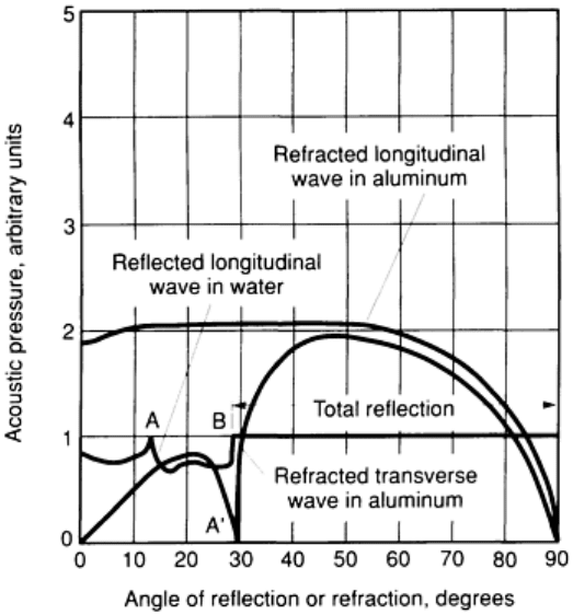
Fig. 6 Variation of acoustic pressure with angle of r
eflection or refraction during immersion ultrasonic inspection
of aluminum. The acoustic pressure of the incident wave equals 1.0 arbitrary unit. Points A and A' correspond to
the first critical angle, and point B to the second critical angle, for this system.
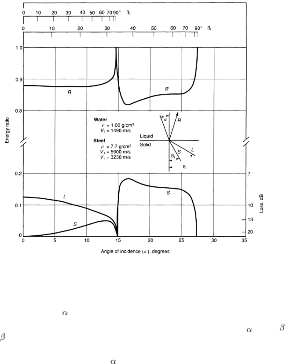
Fig. 7 Partition of acoustic energy at a water/steel interface. The reflection coefficient, R, is equal to 1 - (L
+
S), where L is the transmission coefficient of the longitudinal wave and S
is the transmission coefficient of the
transverse (or shear) wave.
In Fig. 6, as the incident angle,
1
, is increased, there is a slight drop in the acoustic pressure of the reflected wave, a
corresponding slight rise in the acoustic pressure of the refracted longitudinal wave, and a sharper rise in the acoustic
pressure of the refracted transverse wave. At the first critical angle for the water/aluminum interface (
1
= 13.6°,
1
=
90°, and
t
= 29.2°), the acoustic pressure of the longitudinal waves reaches a peak, and the refracted waves go rapidly to
zero (point A', Fig. 6). Between the first and second critical angles, the acoustic pressure in the reflected longitudinal
wave in water varies as shown between points A and B in Fig. 6. The refracted longitudinal wave in aluminum meanwhile
has disappeared. Beyond the second critical angle (
l
= 28.8°), the transverse wave in aluminum disappears, and there is
total reflection at the interface with no partition of energy and no variation in acoustic pressure, as shown to right of point
B in Fig. 6.
Curves similar to those in Fig. 6 can be constructed for the reverse instance of incident longitudinal waves in aluminum
impinging on an aluminum/water interface, for incident transverse waves in aluminum, and for other combinations of
wave types and materials. Details of this procedure are available in Ref 1. These curves are important because they
indicate the angles of incidence at which energy transfer across the boundary is most effective. For example, at an
aluminum/water interface, peak transmission of acoustic pressure for a returning transverse wave echo occurs in the
sector from about 16 to 22° in the water relative to a line normal to the interface. Consequently, 35 to 51° angle beams in

aluminum are the most efficient in transmitting detectable echoes across the front surface during immersion inspection
and can therefore resolve smaller discontinuities than beams directed at other angles in the aluminum.
Reference cited in this section
1.
A.J. Krautkramer and H. Krautkramer, Ultrasonic Testing of Materials, 1st ed, Springer-Verlag, 1969
Ultrasonic Inspection
Revised by Yoseph Bar-Cohen, Douglas Aircraft Company, McDonnell Douglas Corporation; Ajit K. Mal, University of California, Los
Angeles; and the ASM Committee on Ultrasonic Inspection
*
Attenuation of Ultrasonic Beams
The intensity of an ultrasonic beam that is sensed by a receiving transducer is considerably less than the intensity of the
initial transmission. The factors that are primarily responsible for the loss in beam intensity can be classified as
transmission losses, interference effects, and beam spreading.
Transmission losses include absorption, scattering, and acoustic impedance effects at interfaces. Interference effects
include diffraction and other effects that create wave fringes, phase shift, or frequency shift. Beam spreading involves
mainly a transition from plane waves to either spherical or cylindrical waves, depending on the shape of the transducer-
element face. The wave physics that completely describe these three effects are discussed in Ref 1 and 2.
Acoustic impedance effects (see the section "Acoustic Impedance" in this article) can be used to calculate the
amount of sound that reflects during the ultrasonic inspection of a testpiece immersed in water. For example, when an
ultrasonic wave impinges at normal incidence (
1
= 0°) to the surface of the flaw-free section of aluminum alloy 1100
plate during straight-beam inspection, the amount of sound that returns to the search unit (known as the back reflection)
has only 6% of its original intensity. This reduction in intensity occurs because of energy partition when waves are only
partly reflected at the aluminum/water interfaces. (Additional losses would occur because of absorption and scattering of
the ultrasonic waves, as discussed in the sections "Absorption" and "Scattering" in this article.)
Similarly, an energy loss can be calculated for a discontinuity that constitutes an ideal reflecting surface, such as a
lamination that is normal to the beam path and that interposes a metal/air interface larger than the sound beam. For
example, in the straight-beam inspection of an aluminum alloy 1100 plate containing a lamination, the final returning
beam, after partial reflection at the front surface of the plate and total reflection from the lamination, would have a
maximum intensity 8% of that of the incident beam. By comparison, only 6% was found for the returning beam from the
plate that did not contain a lamination. Similar calculations of the energy losses caused by impedance effects at
metal/water interfaces for the ultrasonic immersion inspection of several of the metals listed in Table 1 yield the
following back reflection intensities, which are expressed as a percentage of the intensity of the incident beam:
Material
Back reflection intensity, %
of incident beam intensity
Magnesium alloy M1A
11.0
Titanium
3.0

Type 302 stainless steel
1.4
Carbon steel
1.3
Inconel
0.7
Tungsten 0.3
The loss in intensity of returning ultrasonic beams is one basis for characterizing flaws in metal testpieces. As indicated
above, acoustic impedance losses can severely diminish the intensity of an ultrasonic beam. Because a small fraction of
the area of a sound beam is reflected from small discontinuities, it is obvious that ultrasonic instruments must be
extremely sensitive to small variations in intensity if small discontinuities are to be detected. The sound intensity of
contact techniques is usually greater than that of immersion techniques; that is, smaller discontinuities will result in higher
amplitude signals. Two factors are mainly responsible for this difference, as follows.
First, the back surface of the testpiece is a metal/air interface, which can be considered a total reflector. Compared to a
metal/water interface, this results in an approximately 30% increase in back reflection intensity at the receiving search
unit for an aluminum testpiece coupled to the search unit through a layer of water.
Second, if a couplant whose acoustic impedance more nearly matches that of the testpiece is substituted for the water,
more energy is transmitted across the interface for both the incident and returning beams. For most applications, any
couplant with an acoustic impedance higher than that of water is preferred. Several of these are listed in the nonmetals
group in Table 1. In addition to the liquid couplants listed in Table 1, several semisolid or solid couplants (including
wallpaper paste, certain greases, and some adhesives) have higher acoustic impedances than water.
The absorption of ultrasonic energy occurs mainly by the conversion of mechanical energy into heat. Elastic motion
within a substance as a sound wave propagates through it alternately heats the substance during compression and cools it
during rare-faction. Because heat flows so much more slowly than an ultrasonic wave, thermal losses are incurred, and
this progressively reduces energy in the propagating wave. A related thermal loss occurs in polycrystalline materials; a
thermoelastic loss arises from heat flow away from grains that have received more compression or expansion in the
course of wave motion than did adjacent grains. For most polycrystalline materials, this effect is most pronounced at the
low end of the ultrasonic frequency spectrum.
Vibrational stress in ferromagnetic and ferroelectric materials generated by the passage of an acoustic wave can cause
motion of domain walls or rotation of domain directions. These effects may cause domains to be strengthened in
directions parallel, antiparallel, or perpendicular to the direction of stress. Energy losses in ferromagnetic and ferroelectric
materials may also be caused by a microhysteresis effect, in which domain wall motion or domain rotation lags behind the
vibrational stress to produce a hysteresis loop.
In addition to the types of losses discussed above, other types exist that have not been accounted for quantitatively. For
example, it has been suggested that some losses are caused by elastic-hysteresis effects due to cyclic displacements of
dislocations in grains or grain boundaries of metals.
Absorption can be thought of as a braking action on the motion of oscillating particles. This braking action is more
pronounced when oscillations are more rapid, that is, at high frequencies. For most materials, absorption losses increase
directly with frequency.
Scattering of an ultrasonic wave occurs because most materials are not truly homogeneous. Crystal discontinuities, such
as grain boundaries, twin boundaries, and minute nonmetallic inclusions, tend to deflect small amounts of ultrasonic
energy out of the main ultrasonic beam. In addition, especially in mixed microstructures or anisotropic materials, mode
conversion at crystallite boundaries tends to occur because of slight differences in acoustic velocity and acoustic
impedance across the boundaries.

Scattering is highly dependent on the relation of crystallite size (mainly grain size) to ultrasonic wavelength. When grain
size is less than 0.01 times the wavelength, scatter is negligible. Scattering effects vary approximately with the third
power of grain size, and when the grain size is 0.1 times the wavelength or larger, excessive scattering may make it
impossible to conduct valid ultrasonic inspections.
In some cases, determination of the degree of scattering can be used as a basis for acceptance or rejection of parts. Some
cast irons can be inspected for the size and distribution of graphite flakes, as described in the section "Determination of
Microstructural Differences" in this article. Similarly, the size and distribution of microscopic voids in some powder
metallurgy parts, or of strengtheners in some fiber-reinforced or dispersion-strengthened materials, can be evaluated by
measuring attenuation (scattering) of an ultrasonic beam.
Diffraction. A sound beam propagating in a homogeneous medium is coherent; that is, all particles that lie along any
given plane parallel to the wave front vibrate in identical patterns. When a wave front passes the edge of a reflecting
surface, the front bends around the edge in a manner similar to that in which light bends around the edge of an opaque
object. When the reflector is very small compared to the sound beam, as is usual for a pore or an inclusion, wave bending
(forward scattering) around the edges of the reflector produces an interference pattern in a zone immediately behind the
reflector because of phase differences among different portions of the forward-scattered beam. The interference pattern
consists of alternate regions of maximum and minimum intensity that correspond to regions where interfering scattered
waves are respectively in phase and out of phase.
Diffraction phenomena must be taken into account during the development of ultrasonic inspection procedures.
Unfortunately, only qualitative guidelines can be provided. Entry-surface roughness, type of machined surface, and
machining direction influence inspection procedures. In addition, the roughness of a flaw surface affects its echo pattern
and must be considered.
A sound beam striking a smooth interface is reflected and refracted; but the sound field maintains phase coherence, and
beam behavior can be analytically predicted. A rough interface, however, modifies boundary conditions, and some of the
beam energy is diffracted. Beyond the interface, a coherent wave must re-form through phase reinforcement and
cancellation; the wave then continues to propagate as a modified wave.
The influence on the beam depends on the roughness, size, and contour of the modifying interface. For example, a plane
wave striking a diaphragm containing a single hole one wavelength in diameter will propagate as a spherical wave from a
point (Huygens) source. The wave from a larger hole will re-form in accordance with the number of wavelengths in the
diameter. In ultrasonic inspection, a 2.5 m (100 in.) surface finish may have little influence at one inspection
frequency and search-unit diameter, but may completely mask subsurface discontinuities at other inspection frequencies
or search-unit diameters.
Near-Field and Far-Field Effects. The face of an ultrasonic-transducer crystal does not vibrate uniformly under the
influence of an impressed electrical voltage. Rather, the crystal face vibrates in a complex manner that can be most easily
described as a mosaic of tiny, individual crystals, each vibrating in the same direction but slightly out of phase with its
neighbors. Each element in the mosaic acts like a point (Huygens) source and radiates a spherical wave outward from the
plane of the crystal face. Near the face of the crystal, the composite sound beam propagates chiefly as a plane wave,
although spherical waves emanating from the periphery of the crystal face produce short-range ultrasonic beams referred
to as side lobes. Because of interference effects, as these spherical waves encounter one another in the region near the
crystal face, a spatial pattern of acoustic pressure maximums and minimums is set up in the composite sound beam. The
region in which these maximums and minimums occur is known as the near field (Fresnel field) of the sound beam.
Along the central axis of the composite sound beam, the series of acoustic pressure maximums and minimums becomes
broader and more widely spaced as the distance from the crystal face, d, increases. Where d becomes equal to N (with N
denoting the length of the near field), the acoustic pressure reaches a final maximum and decreases approximately
exponentially with increasing distance, as shown in Fig. 8. The length of the near field is determined by the size of the
radiating crystal and the wave-length, , of the ultrasonic wave. For a circular radiator of diameter D, the length of the
near field can be calculated from:
(Eq 7)
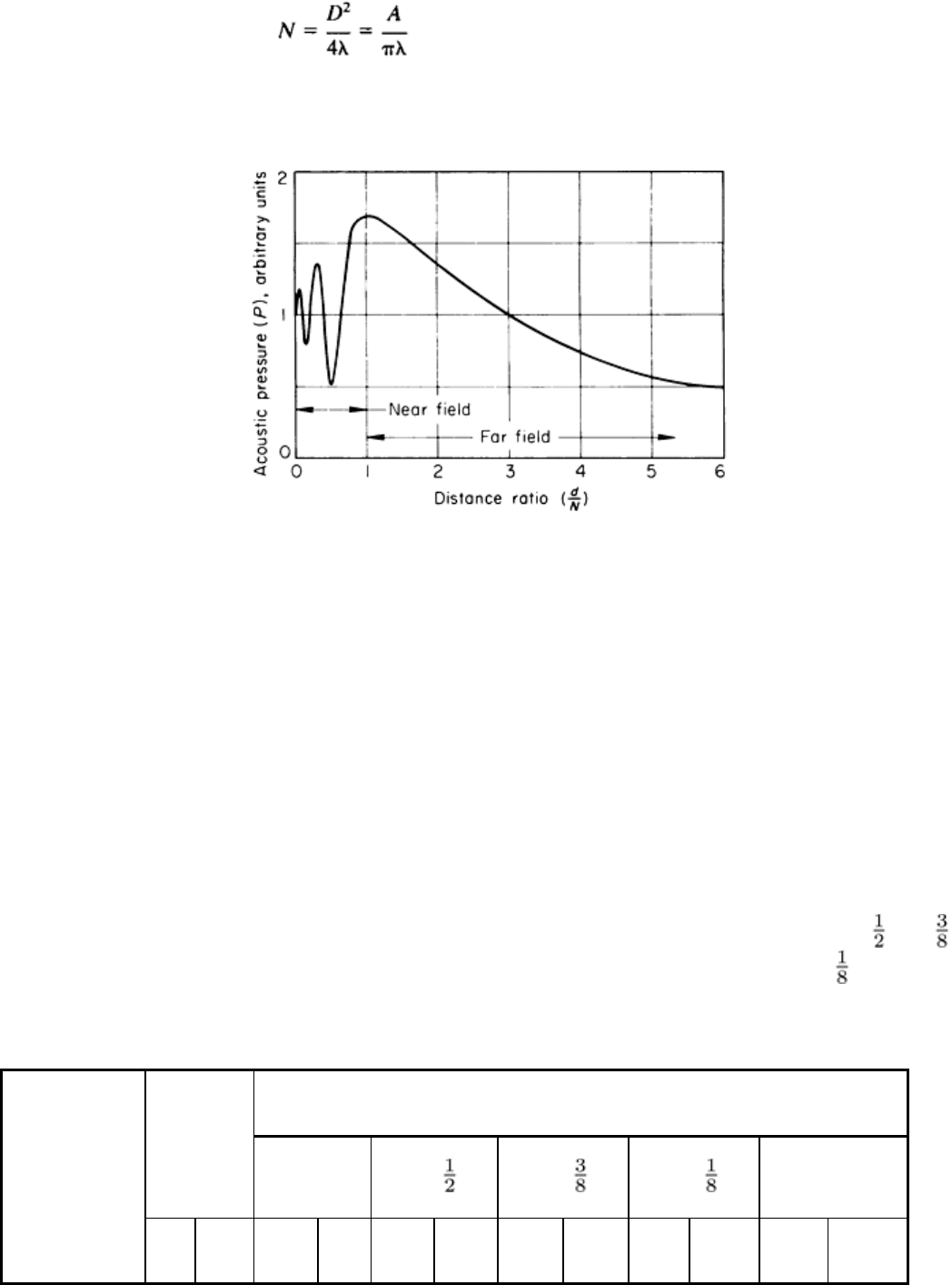
When the wavelength is small with respect to the crystal diameter, the near-field length can be approximated by:
(Eq 8)
where A is the area of the crystal face.
Fig. 8 Variation of acoustic pressure with distance ratio for a circular search unit. Distance ratio i
s the distance
from the crystal face, d, divided by the length of the near field, N.
At distances greater than N, known as the far field of the ultrasonic beam, there are no interference effects. At distances
from N to about 3N from the face of a circular radiator, there is a gradual transition to a spherical wave front. At distances
of more than about 3N, the ultrasonic beam from a rectangular radiator more closely resembles a cylindrical wave, with
the wave front being curved about an axis parallel to the long dimension of the rectangle.
Near-field and far-field effects also occur when ultrasonic waves are reflected from interfaces. The reasons are similar to
those for near-field and far-field effects for transducer crystals; that is, reflecting interfaces do not vibrate uniformly in
response to the acoustic pressure of an impinging sound wave. Near-field lengths for circular reflecting interfaces can be
calculated from Eq 7 and 8. Table 3 lists near-field lengths corresponding to several combinations of radiator diameter
and ultrasonic frequency. The values in Table 3 were calculated from Eq 7 for circular radiators in a material having a
sonic velocity of 6 km/s (4 miles/s) and closely approximate actual lengths of near fields for longitudinal waves in steel,
aluminum alloys, and certain other materials. Values for radiators with diameters of 25, 13, and 10 mm (1, , and in.)
correspond to typical search-unit sizes, and values for radiators with diameters of 3 and 1.5 mm ( and 0.060 in.)
correspond to typical hole sizes in standard reference blocks.
Table 3 Near-field lengths for circular radiators in a material having a sonic velocity of 6 km/s (4 miles/s)
Near-field length for radiator with diameter of:
Wavelength
25 mm (1 in.)
13 mm ( in.)
9.5 mm ( in.)
3.2 mm ( in.)
1.5 mm (0.060 in.)
Frequency, MHz
mm
in. cm in. cm in. cm in. cm in. cm
in.
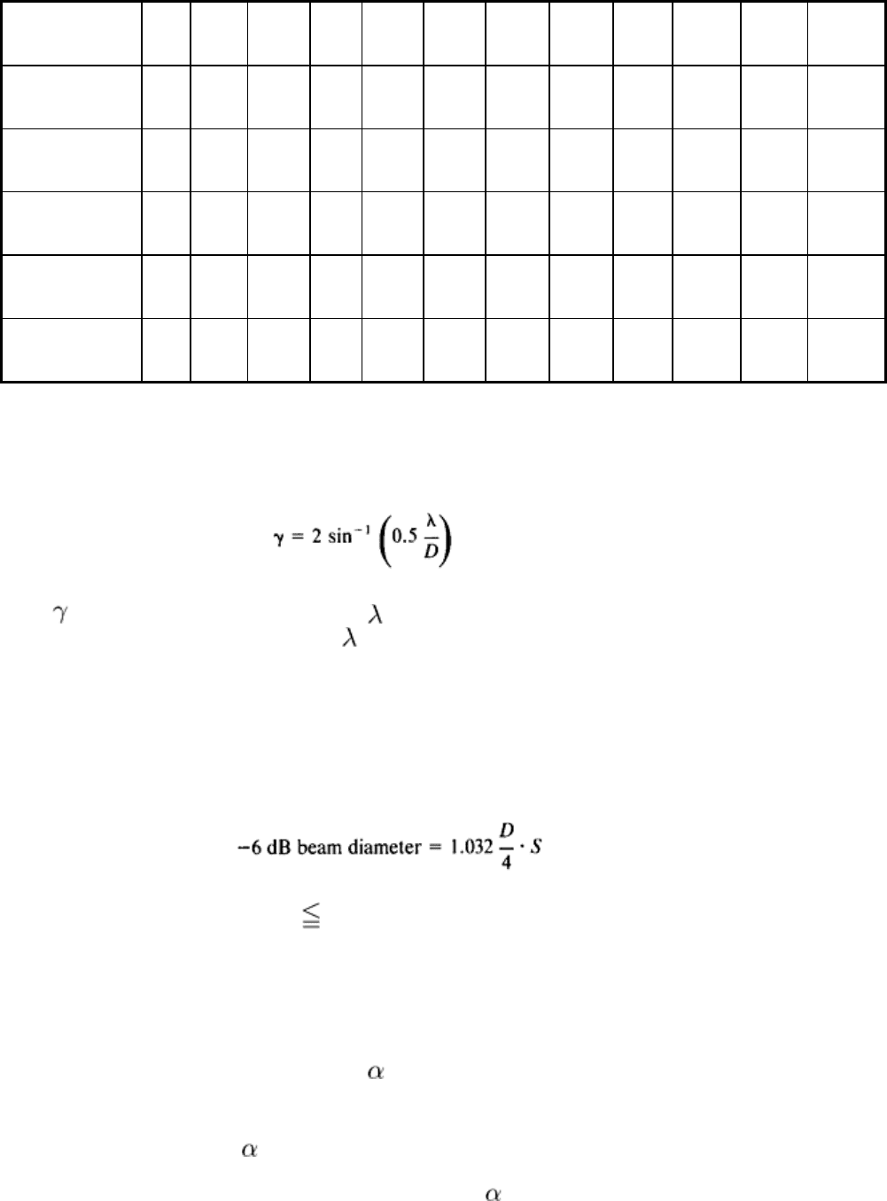
1.0 6.0 0.24 2.5 1.0 0.52 0.20 0.23 0.09 . . . . . . . . .
. . .
2.0 3.0 0.12 5.3 2.1 1.3 0.50 0.68 0.27 0.009
0.0035
. . .
. . .
5.0 1.2 0.04 13.4 5.3 3.3 1.3 1.9 0.75 0.18 0.07 0.02
0.008
10.0 0.6 0.02 27 11 6.7 2.6 3.8 1.5 0.40 0.16 0.08
0.03
15.0 0.4 0.015
40 16 10 4.0 5.7 2.2 0.62 0.24 0.14
0.055
25.0 0.24
0.009
67 26 17 6.7 9.4 3.7 1.04 0.41 0.24 0.095
Beam Spreading. In the far field of an ultrasonic beam, the wave front expands with distance from a radiator. The
angle of divergence from the central axis of the beam from a circular radiator is determined from ultrasonic wavelength
and radiator size as follows:
(Eq 9)
where is the angle of divergence in degrees, is the ultrasonic wavelength, and D is the diameter of a circular radiator.
Equation 9 is valid only for small values of /D, that is, only when the beam angle is small.
When the radiator is not circular, the angle of divergence cannot be assessed accurately by applying Eq 9. For noncircular
search units, beam spreading is most accurately found experimentally.
Beam diameter also depends on the diameter of the radiator and the ultrasonic wavelength. The theoretical equation
for -6 dB pulse-echo beam diameter is:
(Eq 10)
where S is the focusing factor and is 1. Focusing the transducer (S < 1) produces a smaller beam. For a flat (that is,
nonfocused) transducer (S = 1), the beam has a diameter of 0.25 D at the near-field distance N, where N depends on the
ultrasonic wavelength as defined in Eq 7.
The overall attenuation of an ultrasonic wave in the far field can be expressed as:
P = P
0
exp (- L)
(Eq 11)
where P
0
and P are the acoustic pressures at the beginning and end, respectively, of a section of material having a length L
and an attenuation coefficient . Attenuation coefficients are most often expressed in nepers per centimeter or decibels
per millimeter. Both nepers and decibels are units based on logarithms--nepers on natural logarithms (base e) and decibels
on common logarithms (base 10). Numerically, the value of in decibels per millimeter (dB/mm) is equal to 0.868 the
value in nepers per centimeter.
A table of exact attenuation coefficients for various materials, if such data could be determined, would be of doubtful
value. Ultrasonic inspection is a process subject to wide variation in responses, and these variations are highly dependent
on structure and properties in each individual testpiece. Attenuation determines mainly the depth to which ultrasonic

inspection can be performed as well as the signal amplitude from reflectors with a testpiece. Table 4 lists the types of
materials and approximate maximum inspection depth corresponding to low, medium, and high attenuation coefficients.
Inspection depth is also influenced by the decibel gain built into the receiver-amplifier of an ultrasonic instrument and by
the ability of the instrument to discriminate between low-amplitude echoes and electronic noise at high gain settings.
Table 4 Approximate attenuation coefficients and useful depths of inspection for various metallic and
nonmetallic materials
Using 2-MHz longitudinal waves at room temperature
Attenuation coefficient,
dB/mm (dB/in.)
Useful depth
of
inspection, m
(ft)
Type of material inspected
Low: 0.001-0.01 (0.025-
0.25)
1-10 (3-30)
Cast metals: aluminum
(a)
, magnesium
(a)
. Wrought metals: steel, aluminum,
magnesium, nickel, titanium, tungsten, uranium
Medium: 0.01-0.1 (0.25-
2.5)
0.1-1 (0.3-3)
Cast metals
(b)
: steel
(c)
, high-strength cast iron, aluminum
(d)
, magnesium
(d)
. Wrought
metals
(b)
: copper, lead, zinc. Nonmetals: sintered carbides
(b)
, some plastics
(e)
, some
rubbers
(e)
High: >0.1 (>2.5) 0-0.1 (0-
0.3)
(f)
Cast metals
(b)
: steel
(d)
, low-strength cast iron, copper, zinc. Nonmetals
(e)
: porous
ceramics, filled plastics, some rubbers
(a)
Pure or slightly alloyed.
(b)
Attenuation mostly by scattering.
(c)
Plain carbon or slightly alloyed.
(d)
Highly alloyed.
(e)
Attenuation mostly by absorption.
(f)
Excessive attenuation may preclude inspection.
References cited in this section
1.
A.J. Krautkramer and H. Krautkramer, Ultrasonic Testing of Materials, 1st ed, Springer-Verlag, 1969
2.
D. Ensminger, Ultrasonics, Marcel Dekker, 1973
Ultrasonic Inspection
Revised by Yoseph Bar-Cohen, Douglas Aircraft Company, McDonnell Douglas Corporation; Ajit K. Mal, University of California, Los
Angeles; and the ASM Committee on Ultrasonic Inspection
*
