ASM Metals HandBook Vol. 17 - Nondestructive Evaluation and Quality Control
Подождите немного. Документ загружается.

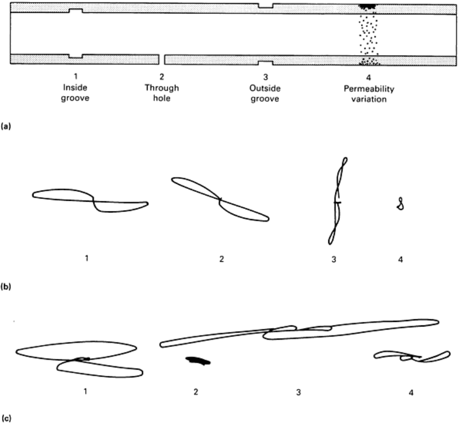
Fig. 34 Signals obtained from type 439 stainless steel calibration tube when using saturation probes. (a) Cross-
sectional view of calibration tube showing location of discontinuities. (b) Signals obtained at each discontinuity
shown in (a) using a probe
with 98% saturation. (c) Signals obtained at each discontinuity shown in (a) using a
probe with 89% saturation
Inspection for fretting wear in ferromagnetic tubes presents an even more difficult problem. Probes capable of complete
saturation of unsupported tube sections cannot normally saturate the tube under a carbon steel support. This is because the
magnetic flux takes the lower-reluctance path through the support rather than along the tube.
To saturate under baffle plates requires a probe with radial magnetization. In this case, the magnetic flux remains almost
undisturbed and actually increases slightly under baffle plates. Eddy current signals from a radial saturation probe are
illustrated in Fig. 35. The large signal in Fig. 35(b) from the baffle plate is due to the probe sensing an increase in
permeability of the Monel tube. As a result, the 40% fretting wear, when under the support, causes only minor distortion
to this large signal and is virtually undetectable. The radial saturation probe continues to saturate the Monel tube as it
passes under the carbon steel baffle. As illustrated in Fig. 35(c), 40% fretting wear under the baffle plate is readily
detectable by the vertical component of the vectorially additive signals.
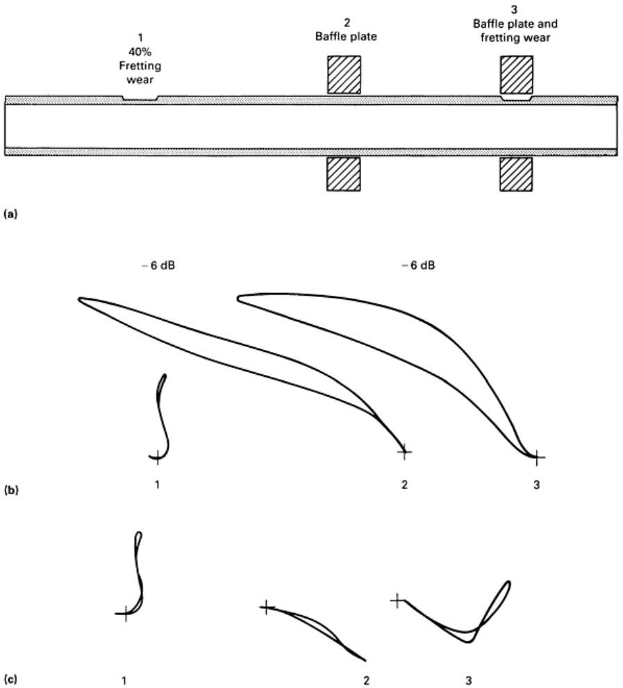
Fig. 35 Signals obtained from Monel 400 calibration tube with simulated fretting wear. (a) Cross-
sectional view
of calibration tube illustrating locations of fretting wear and carbon steel baffles. (b) Signals obtained using an
axial saturation probe a
t the three locations shown in (a). (c) Signals detected using a radial saturation probe
at the three locations shown in (a). The gain of the signals shown in the center and right in (b) has been
decreased by a factor of two, as designated by -6 dB above e
ach curve, to reduce the amplitude of the traces in
both the x and y directions. The remaining four traces are drawn to scale.
Permanent-magnet probes can achieve high magnetic saturation and can provide clear, undistorted defect signals. False
ferromagnetic indications are eliminated, and defect depth can be determined, eliminating unnecessary tube plugging.
Inspection can be performed on ferromagnetic tubing such as Monel 400, 3Re60, and type 439 stainless steel. Only if
thick deposits are present in the bore of the tube must the tube be cleaned prior to testing; no other surface preparation is
required. Inspection speeds are comparable to nonferromagnetic testing, typically 0.5 m/s (1.6 ft/s). Inspection costs are
similar to those of nonferromagnetic tube inspections, and only conventional instrumentation is needed.
Example 3: Comparison of Skin Depth Test Frequency Versus Foerster Limit Frequency
Methods to Obtain Optimum Test Frequency in Eddy Current Inspection of Type 304
Stainless Tubing.
In eddy current inspection, test frequency is an essential test parameter. Traditional nonmagnetic testing methods employ
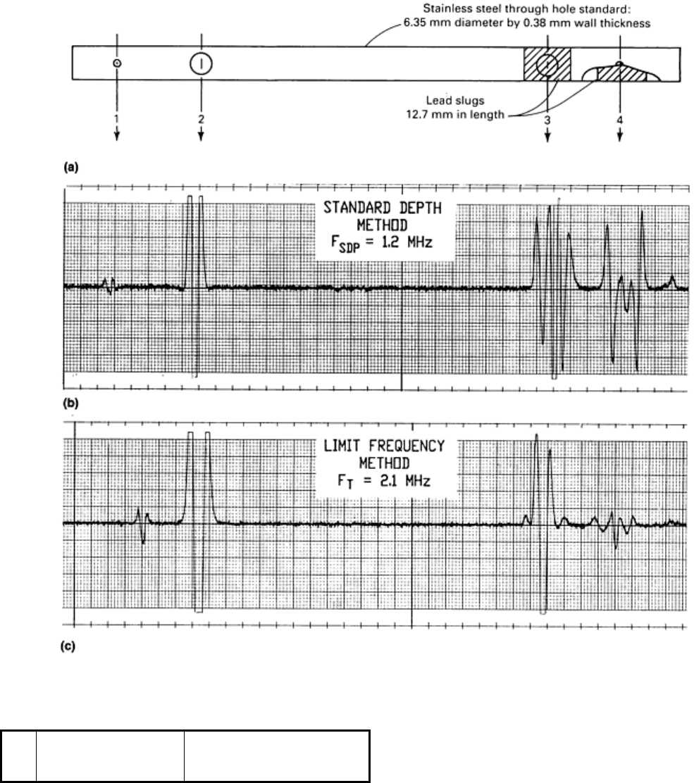
the standard depth of penetration (SDP) or skin depth approach for frequency selection (Ref 5, 6). Figure 36 shows a
comparison between the SDP and the Förster limit frequency, F
g
, approaches to frequency selection for defect testing in
stainless tubing filled with conducting material (Ref 7, 8, 9). The standard used in the comparison was a type 304 stainless
steel tube (6.35 mm, or 0.250 in., OD × 5.54 mm, or 0.218 in., ID) with through holes 3.81 mm (0.150 in.) and 1.11 mm
(0.0437 in.) in diameter drilled at opposite ends. At one end, lead slugs were placed inside the tube beneath the through
holes.
No.
Defect type
Hole diameter through one wall
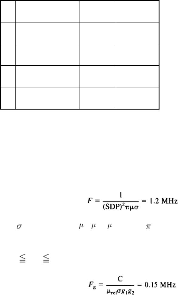
mm
in.
1 Through hole 1.11
0.044
2 Through hole 3.81
0.150
3 Through hole with slug 3.81
0.150
4 Through hole with slug
1.11 0.044
Fig. 36 Comparison of skin depth test frequency, F
SDP
, versus optimum test frequency, F
T
, for a type 304
stainless steel tube. (a) Schematic indicating size an
d location of discontinuities in tube. (b) Plot of eddy current
inspection of tube with 1.2-MHz test frequency. (c) Plot of eddy current inspection of tube with 2.1-
MHz
optimum test frequency derived from F
g
. See text for discussion.
Figure 36(b) shows the results when the SDP method was used to select frequency. In this case, the lead slugs masked the
through holes. For the SDP method, the test frequency was determined as follows:
(Eq 3)
where = 0.14 × 10
7
mho/m, = (
rel
×
0
= (1.02 × 4 × 10
-7
H/m), and SDP = 3.81 × 10
-4
m (tube wall thickness).
Figure 36(c) shows the results of testing at a frequency determined by the F
g
method. In this case, the presence of lead
slugs was suppressed. For test situations of this type, the optimum test frequency, F
T
, will be in the range of 2 to 20 times
F
g
or 2 F
T
/F
g
20. In this case:
(Eq 4)
where C = 5.066 × 10
5
(unitless constant of proportionality), σ= 0.14 × 10
7
mho/m (conductivity of type 304 stainless
steel), μ
rel
= 1.02 (relative permeability), g
1
= 5.54 × 10
-3
m (tube inside diameter), and g
2
= 6.35 × 10
-3
m (tube outside
diameter).
By testing the multiple frequencies in the range (F
T
= 0.3 to 3.0 MHz), an optimum is determined. In this case, 2.1 MHz
was found to be the best frequency, using:
F
T
= 14F
g
(Eq 5)
Substituting for F
g
yields:
F
T
= 14(0.15 MHz) = 2.1 MHz
(Eq 6)
In practical applications, the inspector can try both the SDP and F
g
approaches for selecting an optimum frequency. A
practical application would be the inspection of nuclear fuel rods. Uranium pellets encased in thin-wall metal tubing
require defect inspection of the tube wall. Gaps between adjacent fuel pellets yield nonrelevant indications at low values
of F
g
. Therefore, in this case, the Foerster frequency selection method would produce the best results (Ref 10). It should
be noted that the F/F
g
equation derived from normalized impedance diagrams does not relate to the depth of penetration
and therefore cannot be used to measure skin depth using eddy current testing.
Tube Outside Diameter Over 75 mm (3 in.)
When the diameter of a tube exceeds about 75 mm (3 in.), it is generally no longer practical to inspect with an external
encircling coil for reasons of flaw resolution. A satisfactory technique for larger diameters is the use of multiple probes.
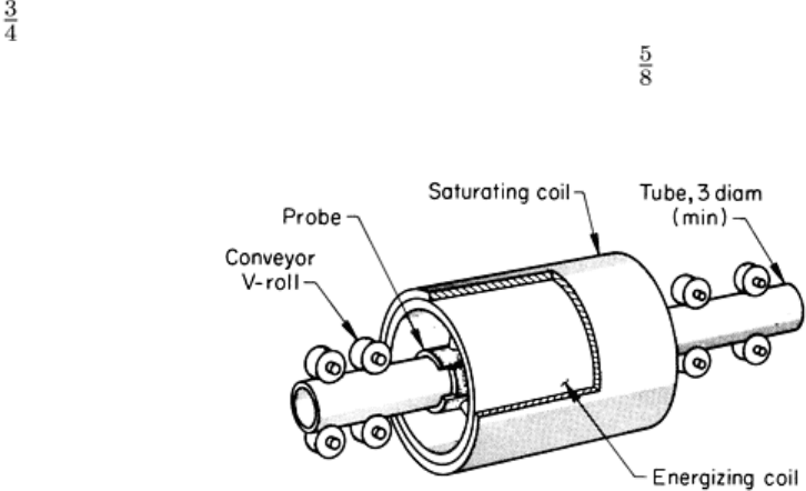
In many respects, a multiple-probe inspection is similar to encircling coil inspection (Fig. 37). An encircling saturating
coil is used when inspecting ferromagnetic materials, and an encircling energizing, or primary, coil is employed. Instead
of an encircling detector, or secondary, coil, however, the detector is composed of several mechanically and electrically
separate probe-coil assemblies. The number of probe assemblies is dependent on the diameter of the tube to be inspected.
Each probe assembly consists of several individual probes. The probes are typically about 50 mm (2 in.) long and have a
19 mm ( in.) square cross section containing differential windings. The probes are electrically balanced individually and
then wired in series. A probe assembly for the inspection of a 245 mm (9 in.) diam tube, for example, would contain 14
probes.
Fig. 37 Multiple-
probe setup and encircling coil components for the continuous eddy current inspection of
ferromagnetic or nonferromagnetic tubes over 75 mm (3 in.) in diameter
As shown in Fig. 37, the probe assemblies are contoured to the curvature of the tube and are designed to ride directly on
the surface of the tube on hardened wear shoes embedded in the assemblies. Typically, four probe assemblies are
employed. In this case, each assembly inspects slightly more than one-quarter of the circumference of the tube. The
assemblies are stagger-mounted so that there is some overlapping of inspected areas. The probe assemblies are each
mounted to an arm that brings them into contact with the tube for inspection or retracts them to a protected location when
the end of the tube is being inserted into the inspection station.
Test signals from each probe assembly are usually fed to a separate inspection circuit and marking system, although the
outputs of the circuits can be combined for operating a common alarm or marker. In terms of area covered per detector,
inspection of a 305 mm (12 in.) diam tube in this manner is comparable to inspecting a 75 mm (3 in.) diam tube with an
encircling coil.
Another advantage of multiple probes is improved inspection sensitivity, because the detector is always in close proximity
to the part being inspected. The use of multiple-probe assemblies also localizes discontinuity position within the sector.
Reflection and Transmission Methods
Discontinuities in nonmagnetic tubing such as that made of copper, brass, or aluminum can be detected by the reflection
and transmission methods of eddy current inspection, depending on such variables as the size, location, and orientation of
the discontinuity. When the reflection method is employed, both the primary coil, which excites the electromagnetic field,
and the secondary coil, which detects the discontinuity, are arranged adjacent to each other on either the outside or inside
wall of the tube. When the transmission method is employed, the exciting and receiving coils are placed at opposite walls,
either on the outside or inside diameter. With the transmission method, the receiving coil is affected only by those
electromagnetic fields that have passed through the entire wall of the tube. Consequently, the transmission method is ideal
for indicating tube discontinuities of the same magnitude on inner and outer surfaces with discontinuity signal amplitudes
of the same height.
There are two distinct coil designs associated with the reflection and transmission methods:
• The encircling coil, which encircles the part completely
•
The rotating probe, which spins around the part in a circular path, with or without making contact with
the part
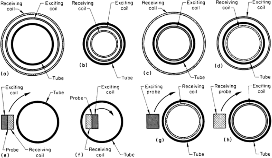
When a cylindrical coil is used inside a tube, it is referred to as an internal coil. Eight possible coil combinations
employed in the eddy current reflection and transmission methods are shown in Fig. 38.
Fig. 38
Eight possible coil combinations employed in the eddy current reflection and transmission methods of
inspecting nonmagnetic tubes. See text for description.
The arrangement shown in Fig. 38(a) is used with the reflection method, and both the exciting and receiving coils
(encircling coils) are located outside the tube. This arrangement is suitable for detecting outer-surface and transverse
discontinuities; it is used for inspecting radioactive fuel cans under water.
The arrangement shown in Fig. 38(b) is also used with the reflection method; both the exciting and receiving coils are
inside the tube. The arrangement is suitable for detecting inner- and outer-surface transverse discontinuities. It is used for
the internal inspection of heat exchanger and reactor tubing.
The arrangement shown in Fig. 38(c) is used with the transmission method and consists of a receiving coil outside the
tube and an exciting coil inside the tube. This arrangement provides good sensitivity to both inner- and outer-surface
discontinuities and is more sensitive to outer-surface discontinuities than the arrangement shown in Fig. 38(a). It is used
in the inspection of six-finned tubes on a continuous basis.
The arrangement shown in Fig. 38(d) is used with the transmission method and consists of an exciting coil outside the
tube and a receiving coil inside the tube. The arrangement provides good sensitivity to both outer- and inner-surface

discontinuities, but provides increased sensitivity to inner-surface discontinuities. It has been used in conjunction with the
arrangement shown in Fig. 38(c) in the inspection of six-finned tubes.
The arrangement shown in Fig. 38(e) is used with the reflection method and consists of an external rotating probe
comprising both the exciting and receiving coils. The arrangement has exceptionally high resolving power for detecting
discontinuities on or beneath the outer surface of the tube and is capable of detecting the smallest surface blemishes. It is
used for inspecting reactor components and fuel elements.
Another rotating probe for use with the reflection method is shown in Fig. 38(f). This probe is similar to that shown in
Fig. 38(e), but is located inside the tube and detects inner-surface discontinuities most effectively. The arrangement is
used for the inspection of reactor U-shaped heat exchanger tubes for corrosion and cracks.
The arrangements shown in Fig. 38(g) and 38(h) are combinations used with the transmission method. That shown in Fig.
38(g) is a combination of exciting rotating probe outside the tube and receiving encircling coil inside the tube. It provides
high sensitivity in the measurement of wall thickness and eccentricity on both thin-wall and thick-wall tubes. The reverse
arrangement is shown in Fig. 38(h); it too is used for measuring tube-wall thickness and eccentricity. Additionally, it is
used to detect and to precisely locate surface and subsurface discontinuities.
References cited in this section
5. R.L. Brown, The Eddy Current Slide Rule, in Proceedings of the 27th National Conference,
American
Society for Nondestructive Testing, Oct 1967
6. H.L. Libby, Introduction to Electromagnetic Nondestructive Test Methods, John Wiley & Sons, 1971
7. E.M. Franklin, Eddy-Current Inspection--Frequency Selection, Mater. Eval., Vol 40, Sept 1982, p 1008
8. L.C. Wilcox, Jr., Prerequisites for Qualitative Eddy Current Testing, in
Proceedings of the 26th National
Conference, American Society for Nondestructive Testing, Nov 1966
9. F. Foerster, Principles of Eddy Current Testing, Met. Prog., Jan 1959, p 101
10.
E.M. Franklin, Eddy-Current Examination of Breeder Reactor Fuel Elements, in Electromagnetic Testing,
Vol 4, Nondestructive Testing Handbook, American Society for Nondestructive Testing, 1986, p 444
Note cited in this section
This section was prepared by Howard Houserman, ZETEC, Inc.
Eddy Current Inspection
Revised by the ASM Committee on Eddy Current Inspection
*
Inspection of Solid Cylinders
As with tubing, the techniques used in the eddy current inspection of solid cylinders differ depending on the diameter of
the cylinder.
Solid Cylinders up to 75 mm (3 in.) in Diameter. Inspection of solid cylinders up to 75 mm (3 in.) in diameter
with an external encircling coil is similar to the inspection of tubes in this size range. The limitation regarding resolution
of discontinuities applies equally to tubes and solid cylinders.
The inspection is performed by passing the cylinder longitudinally through a concentric coil assembly containing a
primary, secondary, and sometimes a saturating coil. When inspecting a solid material using eddy current techniques, it is
difficult to detect discontinuities that are located more than 13 mm ( in.) below the surface. Magnetic field and eddy
current densities decrease to zero at the centers of a cylinder. In addition, the magnetic field density decreases

exponentially with increasing distance from a short coil. The skin effect adds to the decreases in magnetic field density
and eddy current density, but it can be controlled by decreasing the frequency. Eddy current penetration is dependent on
the electrical conductivity and magnetic permeability of the part and on the frequency of the enegizing current.
For a given part, the conductivity is fixed. The permeability of ferromagnetic materials can be made to approach unity
through use of the saturating coil. This permits greater penetration of the eddy currents. For maximum penetration, a low
inspection frequency, such as 400 Hz, is employed. However, as the frequency is lowered, inspection efficiency drops off
rapidly, so that some compromise is usually necessary. Also, at low inspection frequencies, the throughput speed of the
part is limited because the inspection circuit requires interaction with a certain number of cycles of energizing signal in
order to register a discontinuity.
Solid Cylinders Over 75 mm (3 in.) in Diameter. Because of loss of resolution, the inspection of solid cylinders
of 75 mm (3 in.) in diameter, using an external encircling coil, generally is not practical. Consequently, the use of
multiple probes as described above and shown in Fig. 37 for tubes is applied. The multiple-probe techniques for tubes and
solid cylinders are virtually identical.
Eddy Current Inspection
Revised by the ASM Committee on Eddy Current Inspection
*
Machine for Inspection of Tubes on Solid Cylinders
An eddy current inspection machine for detecting surface discontinuities that can be applied to either tubes or solid
cylinders having a wide range of diameters is known as the Orbitest machine. Orbitest machines are provided with a
rotating drum through which the cylinder to be inspected is conveyed. The drum is so mounted that it is free to float to
compensate for any lack of straightness in the part being inspected. Mounted to the drum are two or more search heads,
each of which contains one or two search probes. The search probes are caused to engage the cylinder and orbit about it.
Signal information is taken from the probes to the detection circuitry by way of slip rings. The longitudinal feeding of the
cylinder by conveyor, together with the orbiting of the probes, results in a helical scanning path.
Two paint-marking systems can be utilized at the same time. One orbits with the search heads and marks the precise
locations of discontinuities on the cylinder or tube as they are detected; the other is a stationary system that marks with a
different color the longitudinal position of deep discontinuities. When a dual marking system is used, the depth thresholds
on both marking systems are independently adjustable. In normal operation, one threshold is adjusted to ignore harmless
shallow discontinuities and to mark only those that are deep enough to require removal. The second marking system
identifies only very deep discontinuities. The deepest discontinuity can be removed first if it is not too deep. If it is too
deep, the cylinder or tube can be scrapped before time is wasted in removing shallower discontinuities.
The conveyor speed through the Orbitest machine varies from 12 to 46 m/min (40 to 150 ft/min). Drum rotation speed
ranges from 100 to 180 rev/min. Thus, the scanning path can be controlled as required for products of various diameters
and for the length of discontinuities to be detected.
Eddy Current Inspection
Revised by the ASM Committee on Eddy Current Inspection
*
Inspection of Round Steel Bars
High-speed automatic eddy current inspection machines have been developed to detect seams, laps, cracks, slivers, and
similar surface discontinuities in round steel bars. The machines detect the discontinuities, mark their exact location on
the bar, and automatically sort the bars into three cradles in relation to the depth, length, and frequency of the
discontinuities. One cradle is for prime bars, a second cradle is for bars that can be salvaged by grinding, and the third
cradle is for scrap bars.

Inspection is accomplished by eddy currents that are induced in the bar from a small probe coil, which also serves as the
detector coil. When a surface discontinuity is encountered, the eddy currents are forced to flow beneath the discontinuity
to complete their path. This increases the length of the path of the eddy currents and thus increases the electrical
resistance to the flow of eddy currents in the bar. The change in resistance is proportional to the depth of the
discontinuity. The probe coil detects the change in resistance, and this is interpreted by the instrument in terms of the
depth of the discontinuity.
The probe coil is about 16 mm ( in.) in diameter. It is encapsulated and mounted in a stainless steel housing between
two carbide wear shoes. The probe coil is flexibly supported and mechanically biased to ride against the surface of the
bar. The bars are rotated and propelled longitudinally. This combination of rotary and longitudinal motion causes the
probe (detector) coil to trace on the bar a helical path with a pitch of approximately 75 mm (3 in.). The rolling process by
which bars are produced greatly elongates the natural discontinuities so that they are usually several inches in length. The
75 mm (3 in.) pitch of the helical scan has been found to be more than adequate to detect almost all discontinuities.
A nominal helical scanning speed of 30 m/min (100 sfm) has provided good results. Where higher inspection rates are
desired, multiple-probe-coil machines are used. Such machines have been built with as many as six probe coils.
The locations of discontinuities are marked exactly on the bar by a small, high-speed rotary milling device mounted
downstream of the probe. The milling cutter is brought into momentary contact with the bar precisely one revolution after
the discontinuity has passed the probe coil. This provides a shallow mark exactly on the discontinuity. Because the mark
is a bright milled spot, it is easy to see and will not smear or rub off.
These machines are completely automatic and, after setup, require no attention other than crane service for loading the
feed table and for unloading the cradles after the bars have been inspected. The instrumentation is provided with two
separate alarm controls that can be set as required. For example, one alarm might be set to register all discontinuities over
0.25 mm (0.010 in.) in depth. The second alarm might be set to register all discontinuities over 1.52 mm (0.060 in.) in
depth.
When a bar is being inspected, the outputs from the two alarms are fed into a discontinuity analyzer (computer). This
device can be set to respond to a wide variety of conditions, depending on requirements. For example, a bar that produced
no response from either alarm would always be rated as prime. However, if it is acceptable for a specified percentage of
discontinuities over 0.25 mm (0.010 in.) but less than 1.52 mm (0.060 in.) to be in the material, the discontinuity analyzer
can be set to classify as prime whatever length of discontinuity is permissible. Perhaps a few very short discontinuities
over 1.52 mm (0.060 in.) can be accepted either as prime or as salvageable. If so, the analyzer is set to meet either of these
requirements. The combination of two alarms at different, but adjustable, levels and the versatility of the discontinuity
analyzer provide great flexibility in meeting specific material requirements. Inspection efficiency is also improved
because the inspection can be adjusted to give a product that meets requirements but is not overgraded. This minimizes
costs and scrap losses. These machines have been built to inspect round bars from 9.5 to 114 mm ( to 4 in.) in
diameter and from 1.5 to 15 m (5 to 50 ft) in length.
Eddy Current Inspection
Revised by the ASM Committee on Eddy Current Inspection
*
Inspection of Welds in Welded Tubing and Pipe
Longitudinal welds in welded tubing and pipe can be inspected for discontinuities using eddy current techniques with an
external encircling primary energizing coil and a probe-type differential detector coil. The probe-type detector coil is
located at the longitudinal center in the inner periphery of the primary coil and is arranged so that it inspects the outside
surface of the longitudinal weld.
The inspection, as shown in Fig. 39, is performed by passing the tube or pipe longitudinally through the primary
energizing coil, causing the probe-type detector coil to traverse the longitudinal weld from end to end. The primary coil is
energized with alternating current at a frequency that is suitable for the part being inspected (typically 1 kHz for
ferromagnetic products) and induces the eddy currents in the tube or pipe.
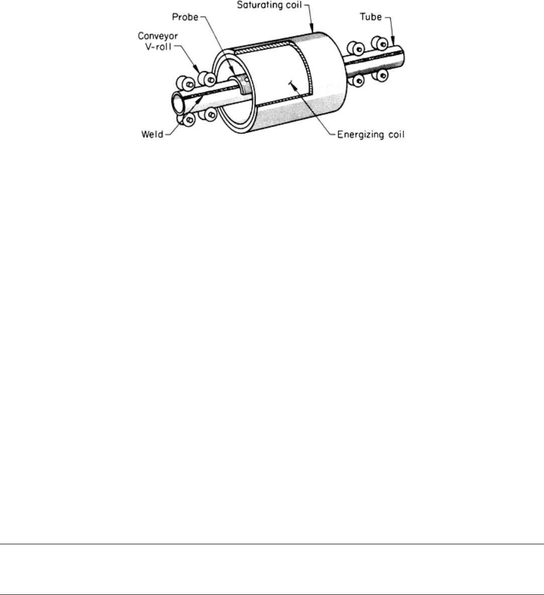
Fig. 39
Setup and coil arrangement for the eddy current inspection of longitudinal welds in ferromagnetic welded
tubing
For the inspection of ferromagnetic products, a dc magnetic-saturating coil is located concentrically around the primary
energizing coil. The dc coil is energized at high current levels to magnetically saturate the tube or pipe. This improves the
penetration of the eddy currents and cancels the effect of magnetic variables.
Because of the circumferential orientation of eddy current flow, this type of inspection is effective in detecting most types
of longitudinal weld discontinuities, such as open welds, weld cracks, hook cracks, black spots, gray spots, penetrators,
and pinholes. Certain types of cold welds having objectionably low mechanical strength may not be detected if the welds
are sufficiently bonded to provide a good electrical path for the eddy currents.
With proper wear shoes and a suitable retracting mechanism to lower the probe-type detector coil onto the pipe at the
front and retract it at the back, the detector-probe-coil assembly can ride directly on the weld area of the pipe. This
provides optimum sensitivity and resolution for the detection of discontinuities. The primary energizing coil may have a
clearance of 25 mm (1 in.) or more to provide room for the probe coil and to provide for easy passage of the pipe. It is
easy to adjust the energy in the primary energizing coil to compensate for any reasonable amount of primary coil
clearance.
It is important that the longitudinal weld be carefully positioned under the probe-type detector coil before the pipe is
passed through the tester. It is essential to provide good conveying equipment for the pipe so that, as the pipe is propelled
longitudinally, the longitudinal weld will always be located under the detector coil.
There is no limit to the maximum diameter of pipe that can be inspected by this procedure. This eddy current method
offers relative simplicity with high sensitivity and resolution. With it, a large majority of objectionable discontinuities can
be detected at high speed and low cost. Throughput speeds of 30 m/min (100 sfm) are common. The conveyor speed
should be controlled to within about ±10%.
Eddy Current Inspection
Revised by the ASM Committee on Eddy Current Inspection
*
Inspection of Plates, Skin Sections Panels, and Sheets
5
The following four examples illustrate typical applications of eddy current testing to detect flaws in plates, panels, and
sheets. Nonferromagnetic materials (Zircaloy-2 and aluminum) are used in all four case histories. Example 7 shows the
use of eddy current inspection to gage glue line thickness in adhesive bonding.
Example 4: Eddy Current Inspection to Detect Shallow Surface Defects in
Zircaloy-2 Plates.
