ASM Metals HandBook Vol. 17 - Nondestructive Evaluation and Quality Control
Подождите немного. Документ загружается.

the cylindrical bar radius and r
c
is the coil radius, is called the fill factor and represents that fraction of the coil area
occupied by the bar.
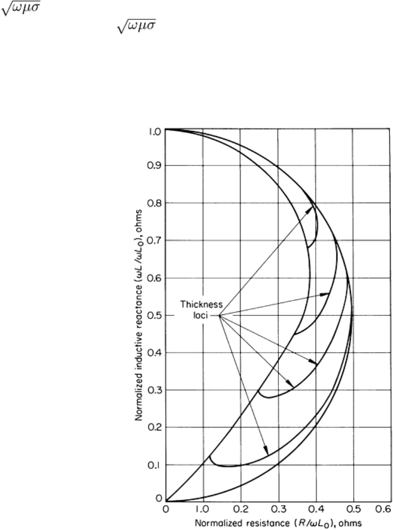
Thickness Loci. Transition from the very thin-wall tube to the solid cylinder produces impedance loci extending
generally from the thin-wall tube locus to a final or end point on the solid-cylinder locus determined by the conductivity
and frequency, as shown in Fig. 18. These loci curve or spiral in a clockwise direction. When the end points of the
thickness loci are points on the solid-cylinder conductivity locus having low values of the reference number kr =
r , the thickness loci are curved but do not rotate around the end point. The spiral effect is more pronounced at
the higher values of kr = r . As in each instance where loci are observed, an opportunity exists to calibrate the
instrument readings so that specific points along a locus represent specific values of the variable of interest. In this case,
the variable is tube-wall thickness. It is important that other inspection variables such as outer radius of tube and
conductivity of tube remain constant if the calibration is to be valid and usable. For example, in Fig. 18, if the tube radius
is varied, whole groups of thickness curves can be generated with accompanying changes of position on the phasor
diagram and changes in sensitivity.
Fig. 18 Impedance diagram showing thickness-loci transition from tube to solid cylinder
The phase-discrimination technique is often used to reduce the effect of a particular variable on one output signal
channel of the eddy current instrument (Fig. 19). The impedance diagram for a probe or pancake coil in the vicinity of a
nonferromagnetic part is shown in Fig. 19(a). Assume that this diagram can be displayed on an oscilloscope. The locus
ABCD represents a thickness locus obtained when the probe coil is in position on the surface of the part. The point D is
called an end point of the thickness locus and as such is located on a conductivity locus for this particular probe. If C
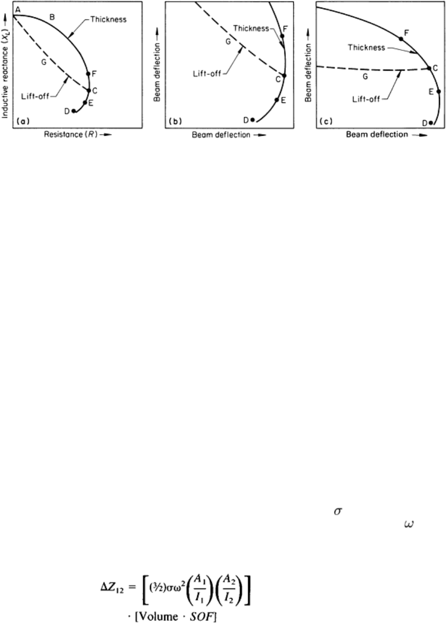
represents the impedance point for nominal or specified thickness, then variations above or below this nominal thickness
value will give readings along the thickness loci at perhaps E or F, respectively. If the probe is lifted from the surface for
the condition of nominal thickness, locus point C, the locus CGA is generated. This new locus is sometimes called a coil
lift-off locus. When thickness is being measured, it is often desired to reduce the effect of small excursions of the probe
from the surface. The phase-discrimination technique can be used for this purpose.
Fig. 19 Phase-discrimination technique for reducing the effect of a particular variable on one output-signal
channel during eddy current inspection. (a) Impedance diagram for a probe or pancake coil in the vicinity of a
nonferromagnetic part. (b) Enlarged view of the area in the vicinity of impedance point C in diagram (a) as
seen on an oscilloscope with the thi
ckness locus in the normal position. (c) Pattern shown in (b) rotated until
the coil lift-off locus is horizontal on the oscilloscope. See text for explanation.
The region of the diagram in the vicinity of impedance point C in Fig. 19(a) is shown enlarged in Fig. 19(b). One output
channel of the instrument produces beam deflections in the vertical direction, and the other in the horizontal direction.
The enlarged diagram in Fig. 19(b) shows that variations in coil lift-off produce signals on both vertical and horizontal
channels. Thus, the lift-off signals will interfere significantly when it is desired to read the effect of thickness variations.
Rotation of the phase-shift control, or phase-discrimination control, rotates the pattern or phasor diagram at the output of
the instrument. Rotating the pattern in Fig. 19(b) until the lift-off locus in the vicinity of point C is horizontal (Fig. 19c)
minimizes the lift-off signal that is effective in the channel producing vertical deflections. Thus, the signal on the vertical
channel now varies with thickness variation with little or no effect from small excursions of the probe. Actually, the
thickness calibration still changes slightly as a function of probe position, and significant errors can still be introduced by
large lift-off excursions of the probe.
Impedance Changes Caused by Small Flaws.
**
The first widely used formula for the impedance change of an
eddy current inspection coil due to a small flaw was given by Burrows (Ref 1). Burrows assumed the flaw to be small
enough that the electromagnetic fields were essentially uniform in the vicinity of the flaw. In practice, this means that the
flaw is small compared to the standard depth of penetration (the skin depth) and the coil radius. He also assumed that, in
general, the flaw was subsurface, and the flaw was small compared to the distance below the surface. For certain flaw
geometries, he was also able to apply the formula to surface flaws. Although these restrictions do not fit the description of
all flaws of interest, the formula allows calculation of the response to very small flaws at the limit of detectability. This
information can be used for estimating ultimate performance and optimizing coil design for detectability.
By restricting the class of materials to nonferromagnetic materials with conductivity and the flaws to voids, Burrows's
formula can be simplified to the following useful version (Ref 2). If a current I
1
of radian frequency in coil 1 causes a
uniform magnetic vector potential of magnitude A
1
at the flaw and if a current I
2
in coil 2 causes a uniform potential of
magnitude A
2
at the flaw, then the change in the mutual impedance due to the presence of the flaw is:
(Eq 2)
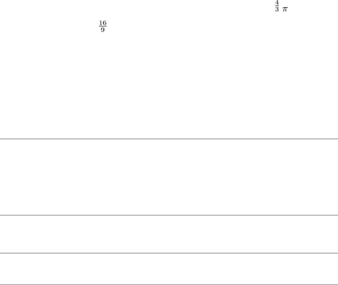
where SOF is the shape and orientation factor of the flaw. If there is only one coil, then A
1
= A
2
, and the mutual
impedance becomes the self-impedance of the coil.
In general, the SOF is a complex function of the shape and orientation of the flaw relative to the eddy current fields.
However, there are two special cases of interest for which the SOF is relatively simple: the sphere and the circular disk, or
penny flaw. For the spherical void, the shape and orientation factor SOF is 1, and the volume is ( ) a
3
, where a is the
radius of the sphere. For a circular disk oriented with the circle perpendicular to the eddy current field direction, the
product of the volume and SOF is ( )a
3
. The same theory can also be applied to surface counterparts of these two flaws:
the hemisphere and the half disk, or half penny flaw. In both of these cases, the product of the volume of SOF is half that
of their subsurface counterparts, because of the volume being halved.
The other part of Burrows's formula requires determination of the magnitudes of the magnetic vector potentials, A
1
and
A
2
. Formulas for calculating the magnetic vector potential fields of coils in proximity to conductors are given in Ref 3.
These formulas are in the form of definite integrals, which can be evaluated by computer for the geometry of interest.
There have been numerous extensions to the Burrows formulation of the impedance change formula that relax the
restriction that the flaw size be small compared to the skin depth and extend the range of flaw shapes for which the SOF
can be calculated. However, the solution remains in the basic form given by Burrows, which shows the dependence of the
impedance change on the square of the field strength and the effective volume and orientation of the flaw.
References cited in this section
1.
M.L. Burrows, "A Theory of Eddy Current Flaw Detection," University Microfilms, Inc., 1964
2.
C.V. Dodd, W.E. Deeds, and W.G. Spoeri, Optimizing Defect Detection in Eddy Current Testing,
Mater.
Eval., March 1971, p 59-63
3.
C.V. Dodd and W.E. Deeds, Analytical Solutions to Eddy-Current Probe-Coil Problems, J. Appl. Phys.,
Vol
39 (No. 6), May 1968, p 2829-2838
Note cited in this section
** This section was prepared by Thomas Kincaid, Boston University.
Eddy Current Inspection
Revised by the ASM Committee on Eddy Current Inspection
*
Inspection Frequencies
The inspection frequencies used in eddy current inspection range from about 200 Hz to 6 MHz or more. Inspections of
nonmagnetic materials are usually performed at a few kilohertz. In general, the lower frequencies, which start at about 1
kHz, are used for inspecting magnetic materials. However, the actual frequency used in any specific eddy current
inspection will depend on the thickness of the material being inspected, the desired depth of penetration, the degree of
sensitivity or resolution required, and the purpose of the inspection.
Selection of inspection frequency is normally a compromise. For example, penetration should be sufficient to reach any
subsurface flaws that must be detected. Although penetration is greater at lower frequencies, it does not follow that as low
a frequency as possible should be used. Unfortunately, as the frequency is lowered, the sensitivity to flaws decreases
somewhat, and the speed of inspection can be curtailed. Normally, therefore, an inspection frequency as high as possible
that is still compatible with the penetration depth required is selected. The choice is relatively simple when detecting
surface flaws only, in which case frequencies up to several megahertz can be used. When detecting flaws at some
considerable depth below the surface, very low frequencies must be used and sensitivity is sacrificed. Under these
conditions, it is not possible to detect small flaws.
In inspecting ferromagnetic materials, relatively low frequencies are normally used because of the low penetration in
these materials. Higher frequencies can be used when it is necessary to inspect for surface conditions only. However, even
the higher frequencies used in these applications are still considerably lower than those used to inspect nonmagnetic
materials for similar conditions.
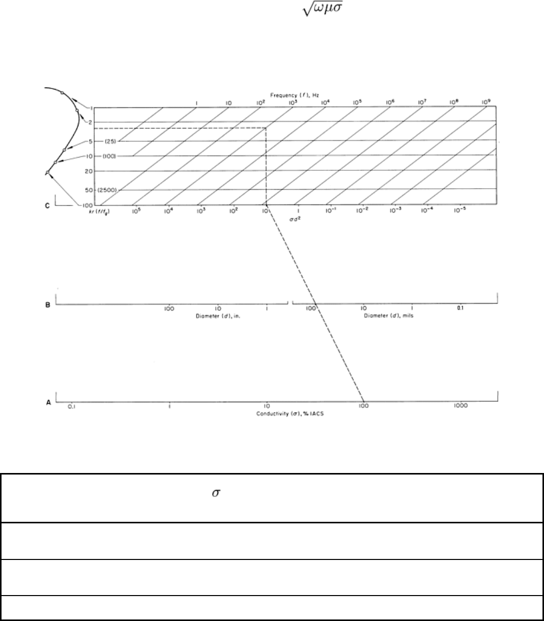
Selection of operating frequency for the inspection of nonferromagnetic cylindrical bars can be estimated using the
chart in Fig. 20. The three main variables on the chart are conductivity, diameter of the part, and operating frequency. A
fourth variable, the operating point on the simple impedance curve, is also taken into account. Usually, the desired
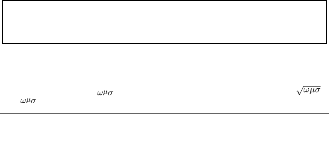
operating point for cylindrical bars corresponds to a value of kr = r , which is approximately 4, but which can be
in the range 2 to 7. In a typical problem, the two variables of the part, conductivity and radius (or diameter), are known,
and it is necessary to find the frequency of operation to determine a particular operating point on the single impedance
diagram.
Step 1 Select the value of electrical conductivity ( ) of the bar in per cent IACS (International Annealed Copper Standard) on
line A.
Step 2 Select the value of the bar diameter (d) in mils or in inches on either of the scales in line B.
Step 3 Lay a straightedge between these two points, extending the line connecting them to intersect line C.
Step 4 Extend a line vertically from the point on line C found in step 3 until it intersects with a horizontal line corresponding to
the desired value of kr.
Step 5 The desired operating frequency is read from the frequency chart (slanted lines), selecting the frequency line that
intersects the intersection determined in step 4.
Fig. 20 Chart for selection of frequency for the inspection of nonferromagnetic cylindrical bars
Some typical impedance points and the corresponding kr values are shown in the small impedance diagram at the top left
of Fig. 20. A column of values of r
2
= (kr)
2
= f/f
g
are also given as a common point between the use of r or
f/f
g
= r
2
as the reference number.
Eddy Current Inspection
Revised by the ASM Committee on Eddy Current Inspection
*
Multifrequency Techniques
**
Instrumentation capable of operating at two or more test frequencies has expanded the capabilities of the eddy current
method by allowing the user to perform simultaneous tests and to provide for signal combinations using multiparameter
techniques. The most widely used application of multifrequency technology has been the inspection of installed heat
exchanger tubing. The thin-wall nonferromagnetic tubing used in the production of steam by nuclear power has been
extensively tested using these multifrequency techniques since 1977. These steam generators contain thousands of tubes,
all of which form a pressure boundary that must be periodically inspected to ensure the safe operating condition of the
power plant. In addition to the necessity for inspecting with inside coils, all test probe positioning for tube selection and
probe insertion/withdrawal functions must be performed remotely due to the radiation levels in the vicinity of the tube
access areas.
Instrumentation Methods. Test coils are typically excited with multifrequency signals using either continuous or
sequential methods.
In the continuous method, excitation currents at each test frequency are simultaneously impressed on the test coil.
The test coil outputs are separated by bandpass filters tuned to the individual test frequencies.
The sequential technique relies on switching between test frequencies and is often referred to as a multiplexed
system. Detection or demodulation, along with signal display capabilities, is provided for each test frequency. Virtually
all the equipment used for this application provides phase and amplitude signal representation through the use of either a
cathode ray oscilloscope or a computer screen. The x and y signal components are derived from phase detector circuits
electrically separated by 90°. The two signal components are displayed as a single moving point on the screen. Through
the use of the storage capabilities of an oscilloscope or other computer methods, the point is traced on the screen to
describe what is commonly called a Lissajous signal. Additional instrumentation capabilities can include provisions for
both differential and absolute coil arrangements as well as the use of multiple-coil arrays.
Test Frequency and Coil Arrangement Selection. The test frequency for the inspection of installed
nonferromagnetic tubing is selected to provide both flaw detection and depth measurement.
Differential Coil Arrangement. With a differential coil arrangement, flaw depth can be related to the change in the
angle of the displayed Lissajous signal. Figures 21(a) and 22(a) show the Lissajous signals resulting from artificial flaws
in Inconel 600 tubing having a wall thickness of 1.3 mm (0.050 in.) tested at both 400 and 100 kHz. The flaws are 100,
80, 60, 40, and 20% through wall flat-bottom holes originating from the outside diameter of this tube. Although a test
frequency of 400 kHz provides a larger range of angles with which to measure flaw depth, testing at 100 kHz can provide
for better detection of minor flaws on the tube outside diameter. The capability to test simultaneously at both frequencies
can be used to accomplish two goals and to confirm a flawed condition by noting the flaw signal with both tests.
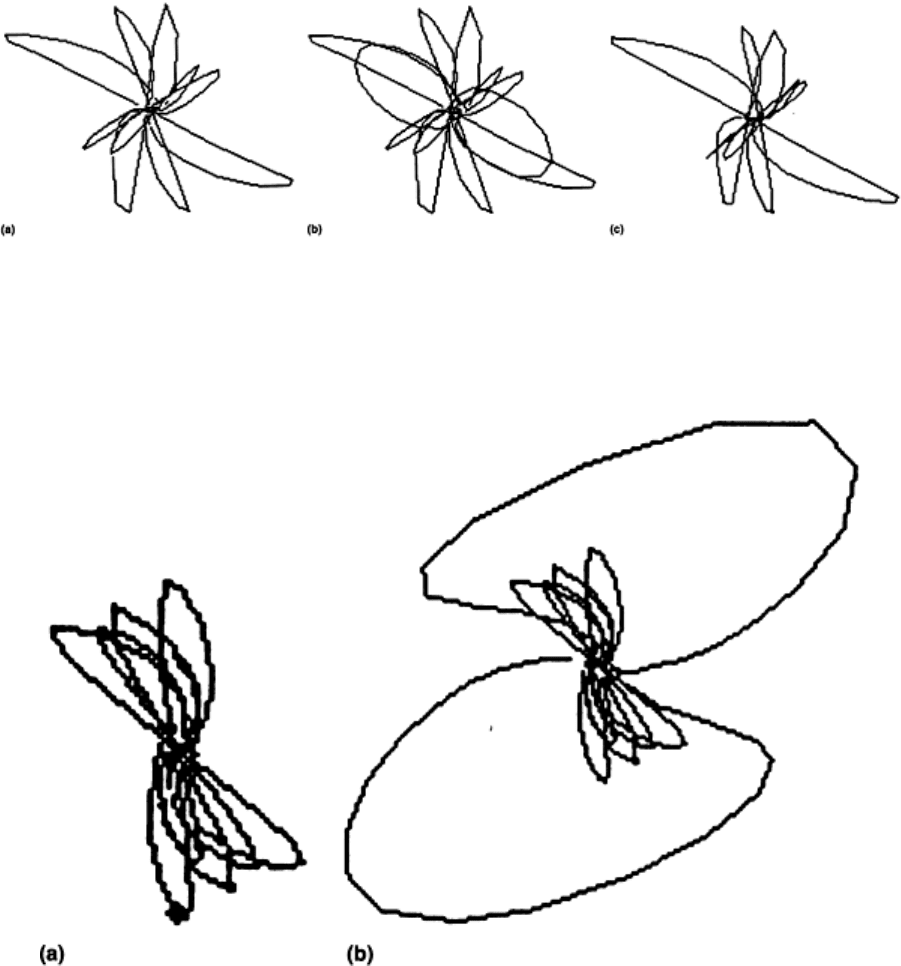
Fig. 21
Lissajous signals resulting from 100, 60, 40, and 20% through wall outside diameter flows when tested
(a) at 400 kHz, (b) at 400 kHz with tube support plate added, and (c) with a digital mixing technique used to
eliminate the signal noise that originates from the tube support plate
Fig. 22 Lissajous signals resulting from 100, 80, 40, and 20% through wall ou
tside diameter flaws tested at 100
kHz (a) without tube support plate and (b) with tube support plate.
Absolute Coil Arrangement. Another factor in determining test frequency might be the desire to measure either
conductive and magnetic depositions occurring on the tube. A lower test frequency can provide better sensitivity to
magnetic deposits that have accumulated on the tube outside diameter. This has been a common practice in an attempt to
determine the relationship between deposits on the outer tube wall surface and the presence of flaws originating in the
same area. On the other hand, testing at a higher frequency might be desirable to provide increased sensitivity to
variations on the inside diameter of the tubing. The latter method, using an absolute coil arrangement, has been
implemented to profile the inside diameter of installed tubing that had been incorrectly expanded with mechanical rollers.
This test has provided information that enabled an assessment of the induced high-stress areas as well as a basis for
selective repair procedures.
The ability to test at multiple frequencies and with both differential and absolute coil arrangements can allow the
discrimination and detection of various flaw mechanisms as well as other anomalies of interest in one test scan. This is of
great importance where inspection time is critical.

Multiparameter techniques are used to separate test variables by combining the results of testing at more than one
frequency. The test variables, or parameters, can include effects such as:
• Lift-off variation caused by probe wobble
• Tube dimension changes resulting from dents, pilgering, and tube expansion processes
• Extraneous signals resulting from tube support plates or depositions (Figures 21(b) and 22(b)
illustrate
the same flaw signals as shown in Fig. 21(a) and 22
(a), with the additional signal resulting from the tube
support plate)
• Flaws caused by wastage, cracking, pitting, and so on
By far the most important aspect of the multiparameter method is to provide for the detection and sizing of flawed
conditions in the presence of the effects of the other variables.
One commonly used technique combines the signal from the selected test frequency for flaw detection with a lower
frequency to eliminate the effects of the signal resulting from a tube support plate. This mixing process has been
accomplished using both analog and digital techniques and combines the output signals from two test frequencies in such
a way that the support plate signal is suppressed or eliminated while the signals resulting from flawed conditions remain.
In the analog instrumentation approach, the x and y signal components of the lower-frequency signal are rotated and/or
scaled such that the resulting support plate signal closely matches the support plate signal from the test frequency used for
flaw detection. The outputs are then combined in a way that subtracts the manipulated lower-frequency signal outputs
from the flaw detection frequency output. The result is a mixed signal that shows no response to support plate influences
yet can be used to detect and measure flaws.
Digitally, results of equal or better quality can be achieved. Rather than manually manipulating the signal with phase
rotators and amplifiers, as is typically done in analog instrumentation, a computer can solve for the best result using
mathematical techniques. Figure 21(c) shows the data of Fig. 21(b) resulting from a digital combination or mix used to
suppress the support plate response. One approach is to establish a set of simultaneous linear equations prescribing a
general signal combination condition. The coefficients of the independent variables are then determined through a least-
squares method to provide the signal output desired.
Note cited in this section
** This section was prepared by Thomas Kincaid, Boston University.
Eddy Current Inspection
Revised by the ASM Committee on Eddy Current Inspection
*
Inspection Coils
The inspection coil is an essential part of every eddy current inspection system. The shape of the inspection coil depends
to a considerable extent on the purpose of the inspection and on the shape of the part being inspected. When inspecting
for flaws, such as cracks or seams, it is essential that the flow of the eddy currents be as nearly perpendicular to the flaws
as possible to obtain a maximum response from the flaws. If the eddy current flow is parallel to flaws, there will be little
or no distortion of the currents and therefore very little reaction on the inspection coil.
Probe and Encircling Coils. Of the almost infinite variety of coils employed in eddy current inspection, probe coils
and encircling coils are the most commonly used. Normally, in the inspection of a flat surface for cracks at an angle to the
surface, a probe-type coil would be used because this type of coil induces currents that flow parallel to the surface and
therefore across a crack, as shown in Fig. 23(a). On the other hand, a probe-type coil would not be suitable for detecting a
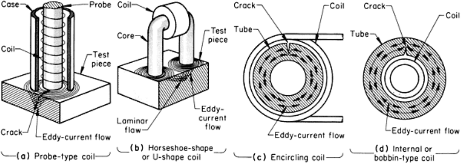
laminar type of flaw. For such a discontinuity, a U-shaped or horseshoe-shaped coil, such as the one shown in Fig. 23(b),
would be satisfactory.
Fig. 23 Types and applications of coils used in eddy current inspection. (a) Probe-
type coil applied to a flat plate
for detection of a crack. (b) Horseshoe-shaped or U-
shaped coil applied to a flat plate for detection of a laminar
flaw. (c) Encircling coil applied to a tube. (d) Internal or bobbin-type coil applied to a tube
To inspect tubing or bar, an encircling coil (Fig. 23c) is generally used because of complementary configuration and
because of the testing speeds that can be obtained with this type of coil. However, an encircling coil is sensitive only to
discontinuities that are parallel to the axis of the tube or bar. The coil is satisfactory for this particular application because,
as a result of the manufacturing process, most discontinuities in tubing and bar are parallel to the major axis. If it is
necessary to locate discontinuities that are not parallel to the axis, a probe coil must be used, and either the coil or the part
must be rotated during scanning. To detect discontinuities on the inside surface of a tube or when testing installed tubing,
an internal or bobbin-type coil (Fig. 23d) can be used. The bobbin-type coil, like the encircling coil, is sensitive to
discontinuities that are parallel to the axis of the tube or bar.
Multiple Coils. In many setups for eddy current inspection, two coils are used. The two coils are normally connected to
separate legs of an alternating current bridge in a series-opposing arrangement so that when their impedances are the
same, there is no output from the pair. Pairs of coils can be used in either an absolute or a differential arrangement (Fig.
24).
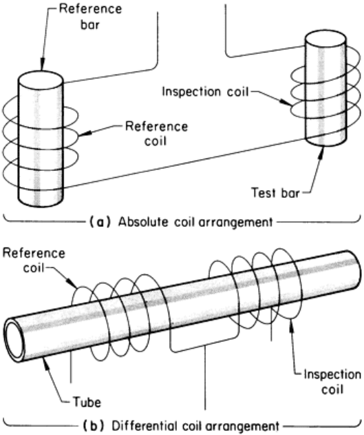
Fig. 24 Absolute and differential arrangements of multiple coils used in eddy current inspection.
See text for
discussion.
Absolute Coil Arrangements. In the absolute arrangement (Fig. 24a), a sample of acceptable material is placed in
one coil, and the other coil is used for inspection. Thus, the coils are comparing an unknown against a standard, with the
differences between the two (if any) being indicated by a suitable instrument. Arrangements of this type are commonly
employed in sorting applications.
Differential Coil Arrangement. In many applications, an absolute coil arrangement is undesirable. For example, in
tubing inspection, an absolute arrangement will indicate dimensional variations in both outside diameter and wall
thickness even though such variations may be well within allowable limits. To avoid this problem, a differential coil
arrangement such as that shown in Fig. 24(b) can be used. Here, the two coils compare one section of the tube with an
adjacent section. When the two sections are the same, there is no output from the pair of coils and therefore no indication
on the eddy current instrument. Gradual dimensional variations within the tube or gross variations between individual
tubes are not indicated, while discontinuities, which normally occur abruptly, are very apparent. In this way, it is possible
to have an inspection system that is sensitive to flaws and relatively insensitive to changes that normally are not of
interest.
Sizes and Shapes. Inspection coils are available in a variety of sizes and shapes. Selection of a coil for a particular
application depends on the type of discontinuity. For example, when an encircling coil is used to inspect tubing or bar for
short discontinuities, optimum resolution is obtained with a short coil. Alternatively, a short coil has the disadvantage of
being sensitive to the position of the part in the coil. Longer coils are not as sensitive to the position of the part, but are
not as effective in detecting very small discontinuities. Small-diameter probe coils have greater resolution than larger
ones, but are more difficult to manipulate and are more sensitive to lift-off variations.
Eddy Current Inspection
Revised by the ASM Committee on Eddy Current Inspection
*
Eddy Current Instruments
This section discusses the various types of detection and readout instrumentation used in eddy current inspection.
Instrument System Operations
Eddy current instruments can be classified as belonging to one of the following categories:
• Resistor and single-coil system
• Bridge unbalance system
• Induction bridge system
• Through transmission system
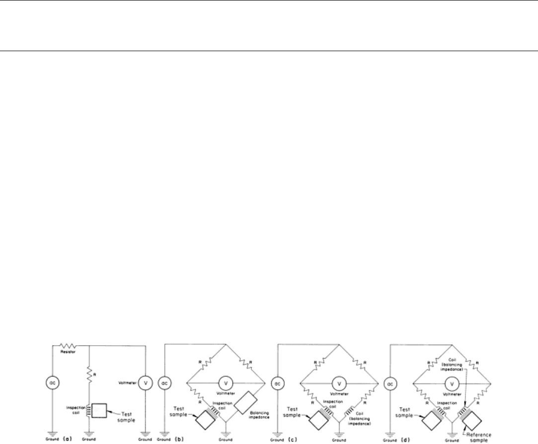
Resistor and Single-Coil System. A simple eddy current instrument, in which the voltage across an inspection coil
is monitored, is shown in Fig. 25(a). This circuit is adequate for measuring large lift-off variations if accuracy is not
extremely important.
Fig. 25
Four types of eddy current instruments. (a) A simple arrangement, in which voltage across the coil is
monitored. (b) Typical impedance bridge. (c) Impedance bridge with dual coils. (d) Impedance bridg
e with dual
coils and a reference sample in the second coil
Bridge Unbalance System. A circuit designed for greater accuracy is shown in Fig. 25(b). This instrument consists of
a signal source, an impedance bridge with dropping resistors, an inspection coil in one leg, and a balancing impedance in
the other leg. The differences in voltage between the two legs of the bridge are measured by an ac voltmeter.
Alternatively, the balancing impedance in the leg opposite the inspection coil may be a coil identical to the inspection
coil, as shown in Fig. 25(c), or it may have a reference sample in the coil, as shown in Fig. 25(d). In the latter, if all the
other components in the bridge were identical, a signal would occur only when the inspection coil impedance deviated
from that of the reference sample.
There are other methods of achieving bridge balance, such as varying the resistance values of the resistor in the upper leg
of the bridge and one in series with the balancing impedance. The most accurate bridges can measure absolute impedance
to within 0.01%. However, in eddy current inspection, it is not how an impedance bridge is balanced that is important, but
rather how it is unbalanced. Because of the effect of undesired variables, eddy current inspections are seldom performed
with the bridge balance.
Figure 26 plots the voltages across an inspection coil, V
1
, and a reference coil, V
2
, for a bridge such as that shown in Fig.
25(c). For simplification, the loading effects the voltmeter has on the system have been omitted. Voltage inspection
values for nine different samples, representing three different levels of magnetic permeability and three different levels of
