ASM Metals HandBook Vol. 17 - Nondestructive Evaluation and Quality Control
Подождите немного. Документ загружается.

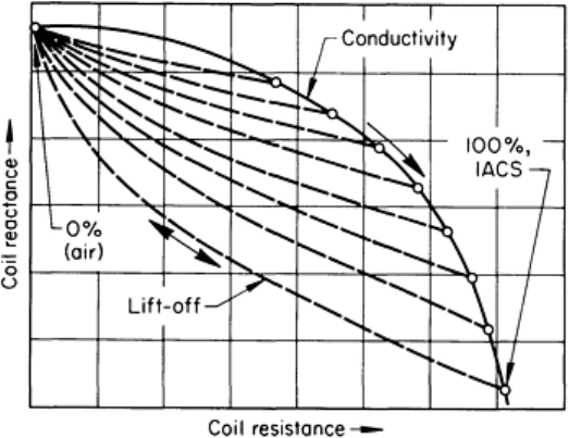
Fig. 8 Magnetization curves for annealed commercially pure iron and nickel
Because eddy currents are induced by a varying magnetic field, the magnetic permeability of the material being inspected
strongly influences the eddy current response. Consequently, the techniques and conditions used for inspecting magnetic
materials differ from those used for inspecting nonmagnetic materials. However, the same factors that may influence
electrical conductivity (such as composition, hardness, residual stresses, and flaws) may also influence magnetic
permeability. Thus, eddy current inspection can be applied to both magnetic and nonmagnetic materials. Although
magnetic conductors also have an electrical conductivity that can vary with changes in material conditions, permeability
changes generally have a much greater effect on eddy current response at lower test frequencies than conductivity
variations.
The fact that magnetic permeability is constant when a ferromagnetic material is saturated can be used to permit the eddy
current inspection of magnetic materials with greatly reduced influence of permeability variations. The part to be
inspected is placed in a coil in which direct current is flowing. The magnitude of current used is sufficient to cause
magnetic saturation of the part. The inspection (encircling) coil is located within the saturation coil and close to the part
being inspected. This technique is generally used when inspecting magnetic materials for discontinuities because small
variations in permeability are not of interest and may cause rejection of acceptable material.
Lift-Off Factor
When a probe inspection coil, attached to a suitable inspection instrument, is energized in air, it will give some indication
even if there is no conductive material in the vicinity of the coil. The initial indication will begin to change as the coil is
moved closer to a conductor. Because the field of the coil is strongest close to the coil, the indicated change on the
instrument will continue to increase at a more rapid rate until the coil is directly on the conductor. These changes in
indication with changes in spacing between the coil and the conductor, or part being inspected, are called lift-off. The lift-
off effect is so pronounced that small variations in spacing can mask many indications resulting from the condition or
conditions of primary interest. Consequently, it is usually necessary to maintain a constant relationship between the size
and shape of the coil and the size and shape of the part being inspected. The lift-off effect also accounts for the extreme
difficulty of performing an inspection that requires scanning a part having a complex shape.
The change of coil impedance with lift-off can be derived from the impedance-plane diagram shown in Fig. 9. When the
coil is suspended in air away from the conductor, impedance is at a point at the upper end of the curve at far left in Fig. 9.
As the coil approaches the conductor, the impedance moves in the direction indicated by the dashed lines until the coil is
in contact with the conductor. When contact occurs, the impedance is at a point corresponding to the impedance of the
part being inspected, which in this case represents its conductivity. The fact that the lift-off curves approach the
conductivity curve at an angle can be utilized in some instruments to separate lift-off signals from those resulting from
variations in conductivity or some other parameter of interest.
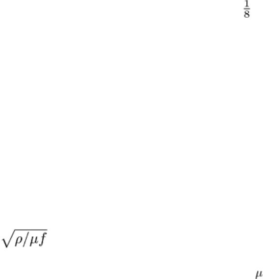
Fig. 9 Impedance-plane diagram showing curves for electrical conductivity and lift-off.
Inspection frequency was
100 kHz.
Although troublesome in many applications, lift-off can also be useful. For example, with the lift-off effect, eddy current
instruments are excellent for measuring the thickness of nonconductive coatings, such as paint and anodized coatings, on
metals.
Fill Factor
In an encircling coil, a condition comparable to lift-off is known as fill factor. It is a measure of how well the part being
inspected fills the coil. As with lift-off, changes in fill factor resulting from such factors as variations in outside diameter
must be controlled because small changes can give large indications. The lift-off curves shown in Fig. 9 are very similar
to those for changes in fill factor. For a given lift-off or fill factor, the conductivity curve will shift to a new position, as
indicated in Fig. 9. Fill factor can sometimes be used as a rapid method for checking variations in outside diameter
measurements in rods and bars.
For an internal, or bobbin-type, coil, the fill factor measures how well the inspection coil fills the inside of the tubing
being inspected. Variations in the inside diameter of the part must be controlled because small changes in the diameter
can give large indications.
Edge Effect
When an inspection coil approaches the end or edge of a part being inspected, the eddy currents are distorted because they
are unable to flow beyond the edge of a part. The distortion of eddy currents results in an indication known as edge effect.
Because the magnitude of the effect is very large, it limits inspection near edges. Unlike lift-off, little can be done to
eliminate edge effect. A reduction in coil size will lessen the effect somewhat, but there are practical limits that dictate the
sizes of coils for given applications. In general, it is not advisable to inspect any closer than 3.2 mm ( in.) from the edge
of a part, depending on variables such as coil size and test frequency.
Skin Effect
In addition to the geometric relationship that exists between the inspection coil and the part being inspected, the thickness
and shape of the part itself will affect eddy current response. Eddy currents are not uniformly distributed throughout a part
being inspected; rather, they are densest at the surface immediately beneath the coil and become progressively less dense
with increasing distance below the surface--a phenomenon known as the skin effect. At some distance below the surface
of a thick part there will be essentially no currents flowing.
Figure 10 shows how the eddy current varies as a function of depth below the surface. The depth at which the density of
the eddy current is reduced to a level about 37% of the density at the surface is defined as the standard depth of
penetration. This depth depends on the electrical conductivity and magnetic permeability of the material and on the
frequency of the magnetizing current. Depth of penetration decreases with increases in conductivity, permeability, or
inspection frequency. The standard depth of penetration can be calculated from:
S = 1980
(Eq 1)
where S is the standard depth of penetration (in inches), ρ is the resistivity (in ohm-centimeters), is the magnetic
permeability (1 for nonmagnetic materials), and f is the inspection frequency (in hertz). Resistivity, it should be noted, is
the reciprocal of conductivity. The standard depth of penetration, as a function of inspection frequency, is shown for
several metals at various electrical conductivities in Fig. 11.
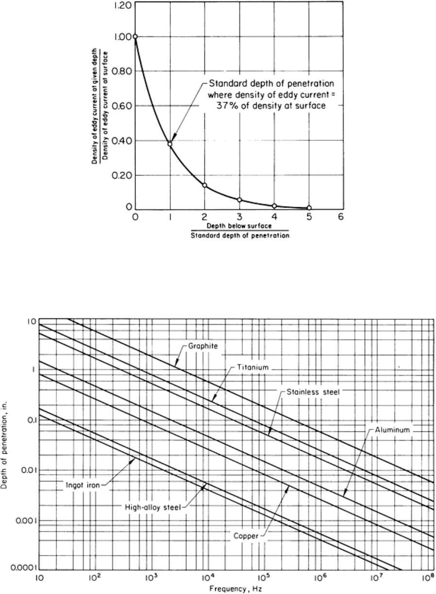
Fig. 10 Variation in density of eddy current as a function of depth below the surface of a conductor--
a variation
commonly known as skin effect
Fig. 11
Standard depths of penetration as a function of frequencies used in eddy current inspection for several
metals of various electrical conductivities
The eddy current response obtained will reflect the workpiece material thickness. It is necessary, therefore, to be sure that
either the material has a constant thickness or is sufficiently thick so that the eddy currents do not penetrate completely
through it. It should be remembered that the eddy currents do not cease at the standard depth of penetration but continue
for some distance beyond it. Normally, a part being inspected must have a thickness of at least two or three standard
depths before thickness ceases to have a significant effect on eddy current response. By properly calibrating an eddy
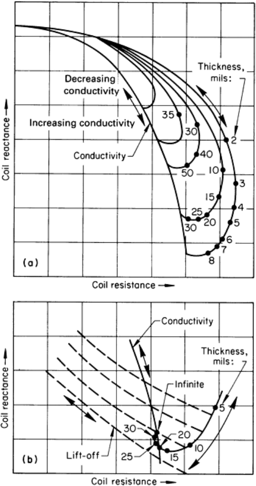
current instrument, it is possible to measure material thickness because of the varying response with thickness. Changing
material thickness follows curves in the impedance plane such as those shown in Fig. 12. As indicated by the curves,
measurements of thickness by the eddy current method are more accurate on thin materials (Fig. 12b) than they are on
thick materials (Fig. 12a). The opposite is true of thickness measurements made by ultrasonics; thus, the two methods
complement each other.
Fig. 12 Typical impedance-
plane diagrams for changing material thickness. (a) Diagram for thick material. (b)
Diagram for thin material on an expanded scale. Inspection frequency was 100 kHz.
Eddy Current Inspection
Revised by the ASM Committee on Eddy Current Inspection
*
Principal Impedance Concepts
This section considers in detail some of the principal impedance concepts that are fundamental to an understanding and
effective application of eddy current inspection.
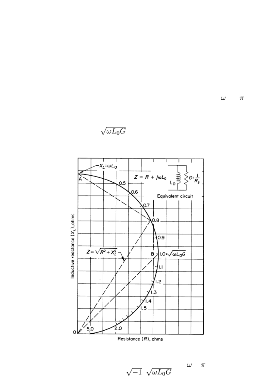
Impedance of a Long Coil Encircling a Thin-Wall Tube. An impedance diagram for a long coil encircling a thin-
wall nonferromagnetic tube, with reactance values plotted as ordinates (horizontal axes) and resistance values plotted as
abscissas (vertical axes), is shown in Fig. 13. When a tube being inspected has zero conductance (the empty-coil
condition), the impedance point is at A. The coil input impedance is all reactance and is equal to L or 2 fL ohms. The
resistance component is zero. The ac resistance of the coil wire is assumed to be constant and is not included in these
diagrams. As the conductance of the part being inspected is caused to increase, the impedance, Z, follows the locus ABO,
for which an example is shown in Fig. 13. This is a circular arc and occurs as shown in Fig. 13 if the tube wall is very thin
compared with the skin depth at the frequency of operation. The impedance locus is marked with reference numbers
calculated from the dimensionless constant and placed on the locus at points corresponding to the respective
impedance values.
Fig. 13 Impedance diagram for a long coil encircling a thin-
wall nonferromagnetic tube, showing also an
equivalent circuit. R: series resistance; R
s
:effective shunt resistance; : 2 f; f: frequency; G
: shunt
conductance; L
0
: coil inductance; Z: impedance; j: ; : dimensionless constant
Several characteristics of the eddy current inspection of tubes or bars are shown in Fig. 13. The simplification resulting
from the assumption that skin effect is absent alters the detailed loci in important ways, as shown in subsequent diagrams.
However, this simplified diagram serves as an introduction to the more detailed diagrams, which include the variations
caused by the skin effect. The locus ABO in Fig. 13 shows the effect on the effective coil impedance of changing the
conductance of the thin-wall tube; because the tube conductance is proportional to the product of the wall thickness of the
tube and the conductivity of the tube material, the impedance loci resulting from variation of thickness coincide with the
locus associated with varying tube material conductivity.
Effects of Changing Operating Frequency. One effect of changing operating frequency is to increase the empty-
coil reactance in direct proportion to the frequency; thus, the impedance diagram grows in size. However, with the part
being inspected in place within the coil, the impedance of the coil for different part conditions and different frequency
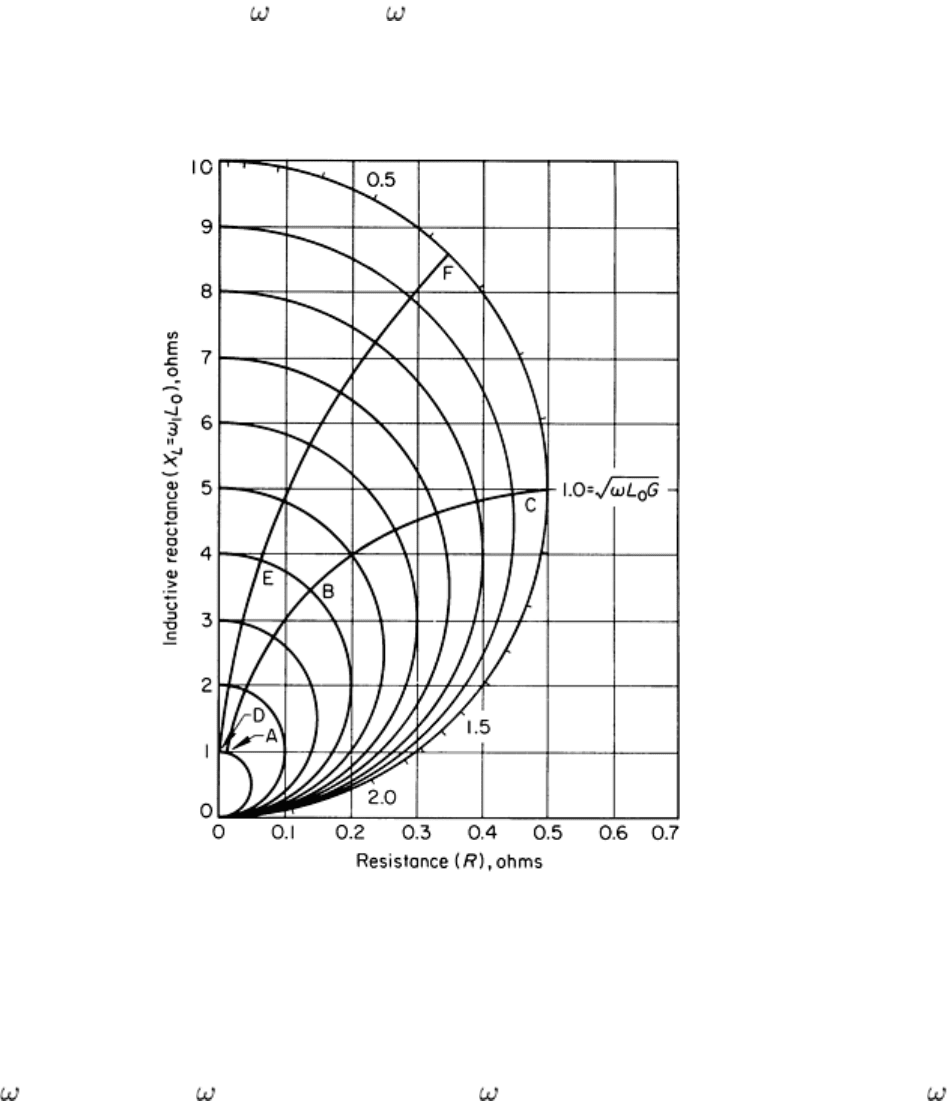
values changes at different rates as the frequency changes. This is shown in Fig. 14 as a prelude to introducing the
concept of impedance normalization. Although frequency is contained in the diagram in Fig. 13, the discussion of that
diagram is based on a fixed frequency. In contrast, Fig. 14 shows the impedance of a long coil encircling a thin-wall
nonferromagnetic tube as a function of frequency. As in Fig. 13, the shape of the impedance locus is semicircular because
of the negligible skin effect, but now there is a separate locus for each frequency considered. Impedance loci are shown
for ten different operating frequencies (
1
through 10
1
). Each locus represents a condition of maximum coupling
between the long solenoid and the encircled tube. This maximum coupling cannot be realized in practice, because the
diameter of the tube and of the coil would need to be equal. The coil wire must occupy some space; therefore, it is not
possible for the exciting current to flow exactly at the surface.
Fig. 14 Impedance diagram for a long coil encircling a thin-
wall nonferromagnetic tube showing impedance as a
function of frequency
The ten curves in Fig. 14 show that the impedance of the empty coil, assuming the coil resistance is negligible, increases
in direct proportion to increases in operating frequency and that this impedance is reactive. The coil at the operating
frequency of
1
has a reactance of
1
L
0
ohms. At a frequency of 2
1
, the reactance is doubled, and so on, until at 10
1
,
the reactance is 10
1
L
0
. In contrast to this linear change of impedance or reactance with frequency, note the nonlinear
change of impedance when the coil has a part within it. First, assume that the part being inspected is a thin-wall tube and
that its reference number is 0.316 at radian frequency
1
. This corresponds to point A on the conductance
locus of the coil at radian frequency
1
. Locus ABC shows the change in impedance of this particular combination of coil
and tube as the frequency is increased from
1
to 10
1
. The impedance variation is far from linear with respect to
frequency variation. Locus DEF similarly shows the impedance variation as frequency varies from
1
to 10
1
when the
tube reference number = 0.2 at radian frequency
1
.
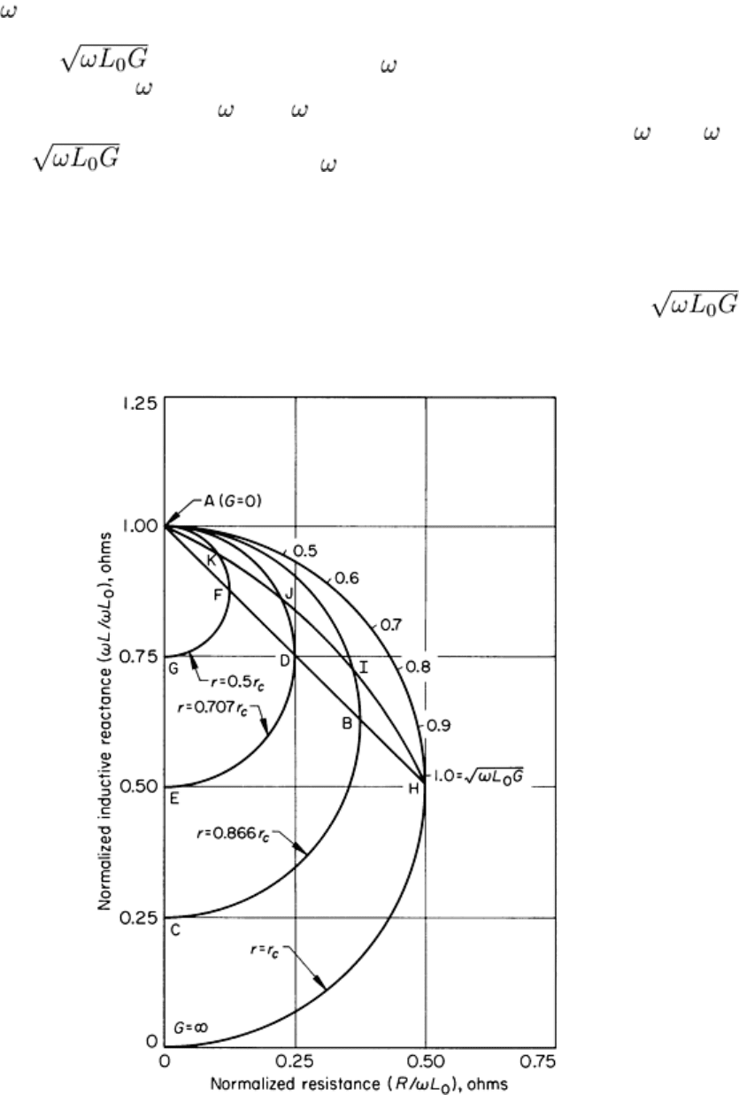
It is customary to normalize groups of impedance curves, such as those in Fig. 14, by dividing both reactance and
resistance values by the impedance or reactance of the empty coil. This transforms all the curves into a single curve, such
as the outer or large curve in Fig. 15, which can be used under a wide range of conditions. When using the single curve,
the nature of its origin must be recalled in interpreting the real effect of varying frequency. Correct relative changes in
impedance are shown on the normalized curve as the frequency is changed in the reference number , but the
actual growing nature of the impedance plane as frequency is increased is hidden.
Fig. 15 Effects of variations in tube radius on the impedance of a long coil of fixed diameter encircling a thin-
wall
nonferromagnetic tube. G: conductance; r: tube radius; r
c
: coil radius.
Several other characteristics of the impedance diagrams for a long coil encircling a tube or bar are shown for simplified
conditions in Fig. 15. The tube wall is assumed to be very thin in relation to the skin depth at the frequency of operation.
The large semi-circular curve represents the locus of impedance resulting from changing tube conductance. Because the
tube wall is assumed to be very thin, skin effect is minimal. Maximum coupling exists between the coil and the tube, and

because the conductance is equal to the product of conductivity of the tube material and the wall thickness in this
simplified example, the conductivity locus and thickness locus are identical. Note, however, that the skin effect must be
negligible for this condition to be obtained. The curves of smaller radius (arcs ABC, ADE, and AFG) are for tubes having
diameters smaller than the coil diameters. As the tube diameter becomes smaller, the electromagnetic coupling between
the coil and tube decreases, and loci such as HBDFA or HIJKA would be generated. The curvature of the loci depends on
the rate at which the conductance of the thin-wall tube varies as the radius is decreased. Figure 15, therefore, shows that
increases in conductance of the thin-wall tube produce semicircular loci whose radii depend on tube diameter and the
amount of coupling (fill factor) between the inspection coil and the tube. The change in conductance may be caused by a
change in either the wall thickness or the electrical conductivity of the tube.
Solid Cylindrical Bar. The normalized impedance diagram for a long encircling coil closely coupled to a solid
cylindrical nonferromagnetic bar is shown in Fig. 16. The locus for the thin-wall tube in Fig. 16 is similar to that
discussed in Fig. 14 and 15. The locus for the solid bar is constructed from an analytical solution of Maxwell's equations
for the particular conditions existing for the solid bar. The reference number quantity for the bar is different from that of
the thin-wall tube to satisfy the new conditions for the solid bar for which the skin effect is no longer negligible. The new
reference number quantity or r is from the theory developed in the application of Maxwell's
equations for a cylindrical conductor. The quantity is the electromagnetic wave propagation constant for a
conducting material, and the quantity is the equivalent of for simplified electric circuits. The quantity
or r is dimensionless and serves as a convenient reference number for use in entering on the
impedance diagram.
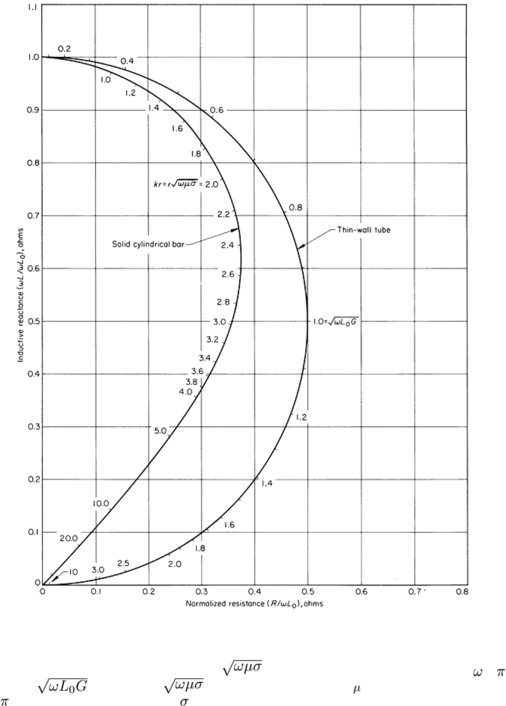
Fig. 16 Normalized impedance diagram for a long coil encircling a solid cylindrica
l nonferromagnetic bar showing
also the locus for a thin-wall tube (which is similar to the loci in Fig. 14 and 15). k
, electromagnetic wave
propagation constant for a conducting material, or ; r, radius of conducting cylinder, meters; , 2 f
;
f, frequency; , equivalent of for simplified electric circuits;
, magnetic permeability of bar,
or = 4 × 10
-7
H/m if bar is nonmagnetic; , electrical conductivity of bar, mho/m; 1.0, coil fill factor
In Fig. 16, the impedance region between the semicircular locus of the impedance for the thin-wall tube and the locus for
the solid cylinder represents impedance values for hollow cylinders or tubes of various wall thicknesses and of materials
with different electrical conductivities. In each case, the outer radius of the tube is equal to the radius of the coil--the ideal
for maximum coupling. The effect on impedance of changing the outer radius of the tube can be projected from the
effects illustrated in Fig. 15, in which a group of electrical-conductivity loci are shown generated by varying the tube
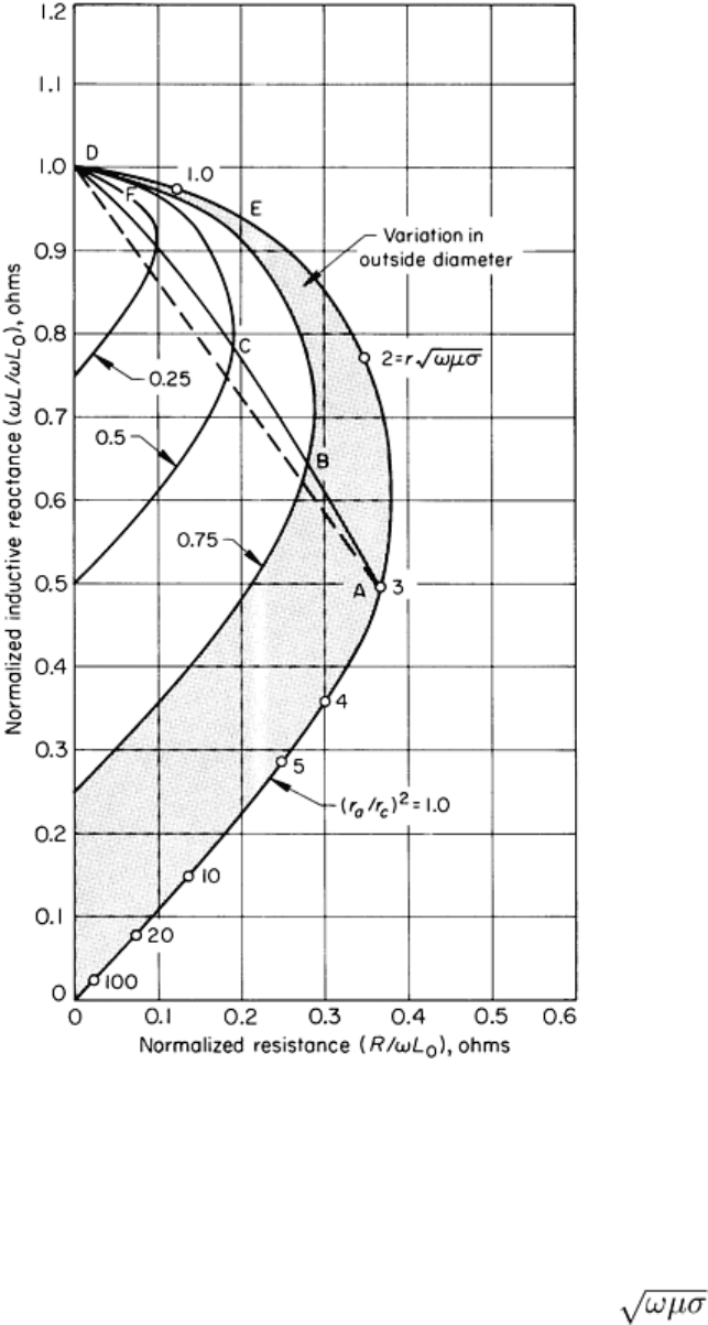
radius. The effect on impedance of varying the outer radius or diameter of the solid cylinder is shown in Fig. 17.
Fig. 17
Effect of variation in bar diameter on the impedance of a long coil encircling a solid cylindrical
nonferromagnetic bar
The locus resulting from varying the outer diameter of the cylindrical bar does not follow a straight path. The reference
number is a function of bar radius, r, and as the radius becomes smaller, the reference number is likewise reduced,
producing a curved radius locus such as the locus ABCD in Fig. 17. At lower values of r , the radius locus
intercepts the conductivity locus at slighter angles and nearly parallels the conductivity locus, as shown in locus EFD in
Fig. 17. This difference in intercept angle is of importance when it is required to discriminate between conductivity
variations and diameter variations. The larger intercept angle permits better discrimination. The factor (r
a
/r
c
)
2
, where r
a
is
