ASM Metals HandBook Vol. 17 - Nondestructive Evaluation and Quality Control
Подождите немного. Документ загружается.

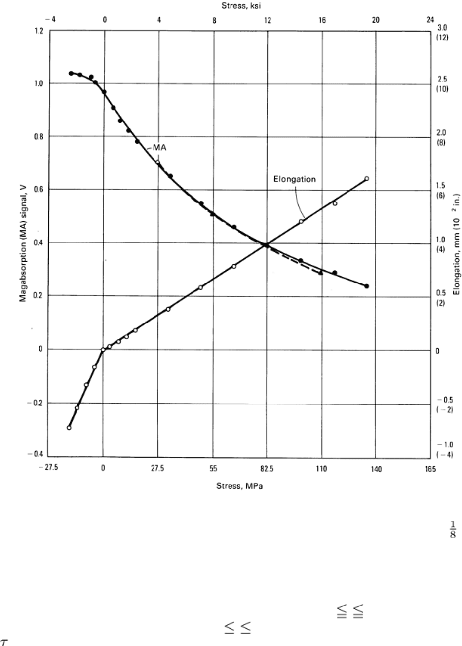
Fig. 26 Variations of the magabsorption signal and strain with stress for a nickel plated 3 mm (
in.) diam
aluminum rod
Another plated rod was annealed for 30 min at 360 °C (680 °F). The graphs of strain versus stress and magabsorption as a
function of stress are given in Fig. 27. The magabsorption amplitude, A, from the nickel is proportional directly to the
applied stress (in psi) to the nickel plated aluminum rod within the range of 2400 τ 10,000 psi and can be expressed
as A = -1.31 × 10
-4
(τ - 16,000). In the region of 10,000 τ 17,000 psi, the curve is fitted by the exponential A = 3.21
exp (- /7150) as shown by the dashed line in Fig. 27.
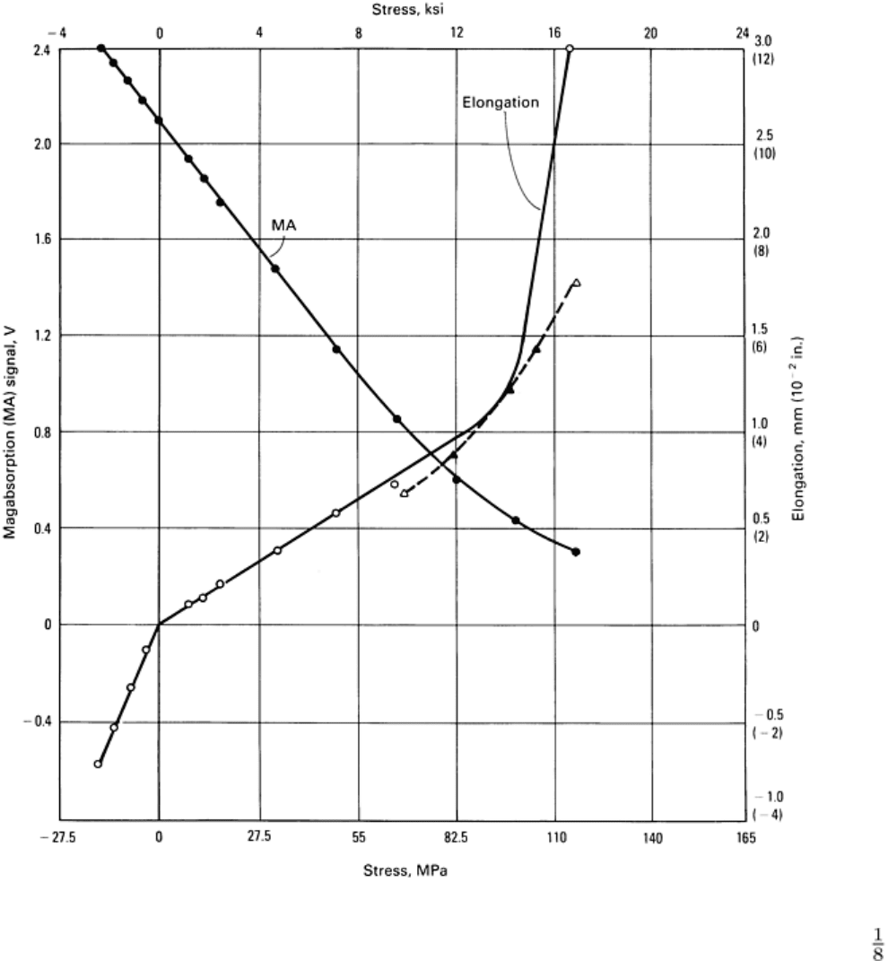
Fig. 27 Variations of the magabsorption signal and stress with strain for an annealed nickel plated 3 mm (
in.) diam aluminum rod
These meager data show that with a calibration curve, the stress in nonferromagnetic materials can be measured using the
magabsorption signals from a thin nickel plating on the nonferromagnetic material. The magabsorption versus stress
graph for the nickel plated aluminum seems to obey nearly the same equation as does the nickel wire. To date, no
measurements of the stress in bars of aluminum with small areas of nickel plating have been accomplished as yet, but are
planned for the future.
Residual Stresses and Magnetism. Asymmetries in magabsorption signals may be indicative of residual stresses or
magnetism. In the case of residual magnetism, the magnetic domains are not entirely haphazard; instead they do some
ordering in a particular direction (Fig. 4f). This will produce asymmetries in the magnitude of the magabsorption signal,
depending on the orientation of the bias field, H
B
, with respect to the orientation of the residual magnetism.
Similarly, residual stresses are indicated by the ratio of magabsorption signals from two orientations (0°, 90°) of the bias
coil. When the 0° and 90° amplitudes are equal, the stress is zero whatever the amplitudes are. When the
parallel/perpendicular ratio is greater than 1, the stress value is positive and is tensile; when the ratio is less than 1, the
stress is negative or compressive. For example, in one investigation, magabsorption measurements were made on steel
samples before and after turning, cutting, and shaping operations. For the turning operation, the sample was reduced in
diameter with a cutting tool; for the cutting operation, a sample was reduced in thickness by a ram shaper; for the shaping
operation, the sample was reduced in thickness by an end mill. With the turning operation, the ratio of the 0° to the 90°
magnitude of the magabsorption decreased from 0.91 to 0.89 when a 130 m (5 mil) cut was made. When a 230 m (9
mil) cut was made, the magabsorption ratio decreased from 0.89 to 0.65. When a 500 m (20 mil) cut was made, the
magabsorption ratio decreased from 0.65 to 0.60. These changes indicated that the turning operation was placing
compressive stress on the testpiece. The testpiece used with the ram shaper was in tension along its length before being
reduced in width. A reduction in width of 760 m (30 mils) by the ram shaper applied perpendicular to the length caused
the surface magabsorption signal ratio to indicate compression after the reduction. With the end mill, the reduction in
thickness resulted in the stress changing from tensile to compressive.
Example 1: Magabsorption Measurement of Residual Stress in a Crankshaft Throw.
Quantitative estimates of residual stress from magabsorption measurements were also performed on a large crank-shaft
throw (Fig. 28) made of 5046 steel. The estimates first required the development of calibration curves as described below.
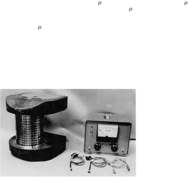
Fig. 28
Magabsorption detector and three detector heads used to perform measurements on the throw of the
crankshaft shown on the left. A closeup view of the detector heads is shown in Fig. 20.
The calibration curves were developed from two samples made of the same material as the crankshaft throw (type 5046
steel). The graph of the parallel-versus-perpendicular peak-to-peak values of the magabsorption signals from two of the
calibration samples are given in Fig. 29. Two straight lines at angles of 45 and 50° relative to the horizontal axis are also
drawn in Fig. 29. The one at 45° is a zero-stress line where the parallel and perpendicular magabsorption signals are the
same magnitude. The line at 50° is the calibration line to be used to determine the calibration constant for the estimate of
residual stress from the magabsorption measurements. Five stress levels (A, B, C, D, and E in Fig. 29) were applied at the
measuring point on each test bar, and the calibration constant was determined as described below.
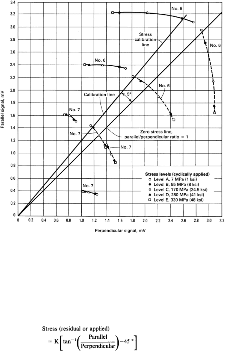
Fig. 29 Graph showing the
plot of the parallel/perpendicular ratios for sample 6 (type 5046 steel) and sample 7
(type 5046 steel)
Previous experiments have indicated that the intersections of the parallel and perpendicular magnitudes for magabsorption
signals at one point for the residual stresses seldom occur along the same line as applied stresses. However, it has been
indicated that the applied stress lines in Fig. 29 probably can be used to determine the residual stress values in general by
following the rule: All points on a radial line from the origin at some angle with respect to the abscissa have the same
value of residual stress. The 45° line should be the locus of points of zero stress where the parallel and perpendicular
values of the magabsorption curve are equal. With the 45° line as a reference, residual or applied stress can be expressed
mathematically as:
(Eq 19)

where K is the calibration constant for the material. When the parallel and perpendicular amplitudes are equal, the stress
is zero whatever the amplitudes are. When the parallel/perpendicular ratio is greater than one, the stress value is positive
and is tension; when the ratio is less than one, the stress is negative or compression.
The calibration constant, K, is obtained from Fig. 29 by the following procedure: (a) draw a calibration line through the
origin at an angle for which an applied stress can be assigned to the intersection of the parallel/perpendicular ratio for the
applied stress and (b), calculate the value of the constant K by inserting the applied stress and the angle into Eq 19.
Before this procedure could be used with the data in Fig. 29, the usable applied stress curve had to be chosen. One of the
applied stress curves from sample No. 7 was chosen because its amplitude was the closest to the residual stress data, and
because its curve shape was close to that obtained from the throw. The calibration proceeded as described. The line at 50°
was chosen for the first calibration value because it intersected the lowest amplitude (dashed curve) for the data from
sample 7 at nearly the value of applied stress level B (closed circle) (55 MPa, or 8 ksi). The 45° line passes through the
No. 7 stress curve (dashed) nearly at level C (open triangle), or where an estimated value of 160 MPa (23.5 ksi) had been
applied. Therefore, the line at an angle of 50° represents a differential applied stress relative to the 45° line of 160 - 55 =
105 MPa (23.5 - 8 = 15.5 ksi). When several values are taken from several lines both above and below the 45° line, the
average value for a line 5° above or below 45° is 100 MPa (15 ksi). Therefore, if both the value of tan
-1
50° and the stress
equal to 100 MPa (15 ksi) are inserted into Eq 19, the value of K is found to be 20 MPa/degree (3 ksi/degree). This
implies that for every degree of offset from the 45° line, points along the line at that offset resulting from signal amplitude
measurements will have the same value of residual stress.
When the value of K is used, calibration lines can be drawn through zero at useful angles relative to the 45° line. Using
these calibration lines and marks, the values of the residual stresses for points on the crankshaft throw were determined.
Residual stress values as high as 600 MPa (87 ksi) tension and 90 MPa (13 ksi) compression were determined.
References cited in this section
3. W.L. Rollwitz, "Magnetoabsorption," Final Report, Research Project No. 712-
4, Southwest Research
Institute, 1958
4. W.L. Rollwitz and A.W. Whitney, "Special Te
chniques for Measuring Material Properties," Technical
Report ASD-TDR-64-123, USAF Contract No. AF-33(657)-10326, Air Force Materials Laboratory, 1964
5.
W.L. Rollwitz and J.P. Classen, "Magnetoabsorption Techniques for Measuring Material Properties,"
Technical Report AFML-TR-65-17, USAF Contract No. AF-33(657)-
10326, Air Force Materials
Laboratory, 1965
6.
W.L. Rollwitz and J.P. Classen, "Magnetoabsorption Techniques for Measuring Material Properties,"
Technical Report AFML-TR-66-76 (Part I), USAF Contract No. AF-33(657)-
10326, Air Force Materials
Laboratory, 1966
7.
W.L. Rollwitz, "Magnetoabsorption Techniques for Measuring Material Properties. Part II. Measurements
of Residual and Applied Stress." Technical Report AFML-TR-66-76 (Part II), USAF Contract No. AF-
33(615)-5068, Air Force Materials Laboratory, 1968
11.
W.L. Rollwitz, "Preliminary Magnetoabsorption Measurements of Stress in a Crankshaft Throw," Summary
Report on Project 15-2438, Southwest Research Institute, 1970
Magabsorption NDE
William L. Rollwitz, Southwest Research Institute
References
1. W.E. Bell, Magnetoabsorption,
Vol 2, Proceedings of the Conference on Magnetism and Magnetic
Materials, American Institute of Physics, 1956, p 305
2. R.M. Bozorth, Magnetism and Electrical Properties, in Ferromagnetism, D. Van Nostrand, 1951, p 745-
768

3. W.L. Rollwitz, "Magnetoabsorption," Final Report, Research Project No. 712-
4, Southwest Research
Institute, 1958
4. W.L. Rollwitz and A.W. Whitney, "Special Techniques for Measuring Material Properti
es," Technical
Report ASD-TDR-64-123, USAF Contract No. AF-33(657)-10326, Air Force Materials Laboratory, 1964
5.
W.L. Rollwitz and J.P. Classen, "Magnetoabsorption Techniques for Measuring Material Properties,"
Technical Report AFML-TR-65-17, USAF Contract No. AF-33(657)-
10326, Air Force Materials
Laboratory, 1965
6.
W.L. Rollwitz and J.P. Classen, "Magnetoabsorption Techniques for Measuring Material Properties,"
Technical Report AFML-TR-66-76 (Part I), USAF Contract No. AF-33(657)-10326, Air Force Mater
ials
Laboratory, 1966
7.
W.L. Rollwitz, "Magnetoabsorption Techniques for Measuring Material Properties. Part II. Measurements
of Residual and Applied Stress." Technical Report AFML-TR-66-76 (Part II), USAF Contract No. AF-
33(615)-5068, Air Force Materials Laboratory, 1968
8. W.L. Rollwitz, Magnetoabsorption, Progress in Applied Materials Research,
Vol 6, E.G. Stanford, J.H.
Fearon, and W.J. McGonnagle, Ed., Heywood, 1964
9. W.L. Rollwitz, Sensing Apparatus for Use With Magnetoabsorption Apparatus, U.S.
Patent 3,612,968,
1971
10.
W.L. Rollwitz, J. Arambula, and J. Classen, Method of Determining Stress in Ferromagnetic Members
Using Magnetoabsorption, 1974
11.
W.L. Rollwitz, "Preliminary Magnetoabsorption Measurements of Stress in a Crankshaft Throw,"
Summary Report on Project 15-2438, Southwest Research Institute, 1970
Electromagnetic Techniques for Residual Stress Measurements
H. Kwun and G.L. Burkhardt, Southwest Research Institute
Introduction
RESIDUAL STRESSES in materials can be nondestructively measured by a variety of methods, including x-ray
diffraction, ultrasonics, and electromagnetics (Ref 1, 2, 3). With the x-ray diffraction technique, the interatomic planar
distance is measured, and the corresponding stress is calculated (Ref 4). The penetration depth of x-rays is of the order of
only 10 in. (400 in.) in metals. Therefore, the technique is limited to measurements of surface stresses. Its use has been
generally limited to the laboratory because of the lack of field-usable equipment and concern with radiation safety.
With ultrasonic techniques, the velocity of the ultrasonic waves in materials is measured and related to stress (Ref 5).
These techniques rely on a small velocity change caused by the presence of stress, which is known as the acoustoelastic
effect (Ref 6). In principle, ultrasonic techniques can be used to measure bulk as well as surface stresses. Because of the
difficulty in differentiating stress effects from the effect of material texture, practical ultrasonic applications have not yet
materialized.
With electromagnetic techniques, one or more of the magnetic properties of a material (such as permeability,
magnetostriction, hysteresis, coercive force, or magnetic domain wall motion during magnetization) are sensed and
correlated to stress. These techniques rely on the change in magnetic properties of the material caused by stress; this is
known as the magnetoelastic effect (Ref 7). These techniques, therefore, apply only to ferromagnetic materials, such as
steel.
Of the many electromagnetic stress-measurement techniques, this article deals with three specific ones: Barkhausen noise,
non-linear harmonics, and magnetically induced velocity changes. The principles, instrumentation, stress dependence, and
capabilities and limitations of these three techniques are described in the following sections.
References
1.
M.R. James and O. Buck, Quantitative Nondestructive Measurements of Residual Stresses, CRC Crit.
Rev.
Solid State Mater. Sci., Vol 9, 1980, p 61
2.
C.O. Ruud, "Review and Evaluation of Nondestructive Methods for Residual Stress Measurement," Final
Report, NP-1971, Project 1395-5, Electric Power Research Institute, Sept 1981
3.
W.B. Young, Ed., Residual Stress in Design, Process, and Material Selection,
Proceedings of the ASM
Conference on Residual Stress in Design, Process, and Materials Selection, Cincinnati, OH,
April 1987,
ASM INTERNATIONAL, 1987
4.
M.R. James and J.B. Cohen, The Measurement of Residual Stresses by X-
Ray Diffraction Techniques, in
Treatise on Materials Science and Technology--Experimental Methods,
Vol 19A, H. Herman, Ed., Academic
Press, 1980, p 1
5.
Y. H. Pao, W. Sachse, and H. Fukuoka, Acoustoelasticity and Ultrasonic Measurement of Residual Stresses,
in Physical Acoustics: Principles and Methods,
Vol XVII, W.P. Mason and R.M. Thurston, Ed., Academic
Press, 1984, p 61-143
6.
D.S. Hughes and J.L. Kelly, Second-Order Elastic Deformation of Solids, Phys. Rev., Vol 92, 1953, p 1145
7.
R.M. Bozorth, Ferromagnetism, Van Nostrand, 1951
Electromagnetic Techniques for Residual Stress Measurements
H. Kwun and G.L. Burkhardt, Southwest Research Institute
Barkhausen Noise
The magnetic flux density in a ferromagnetic material subjected to a time-varying magnetic field does not change in a
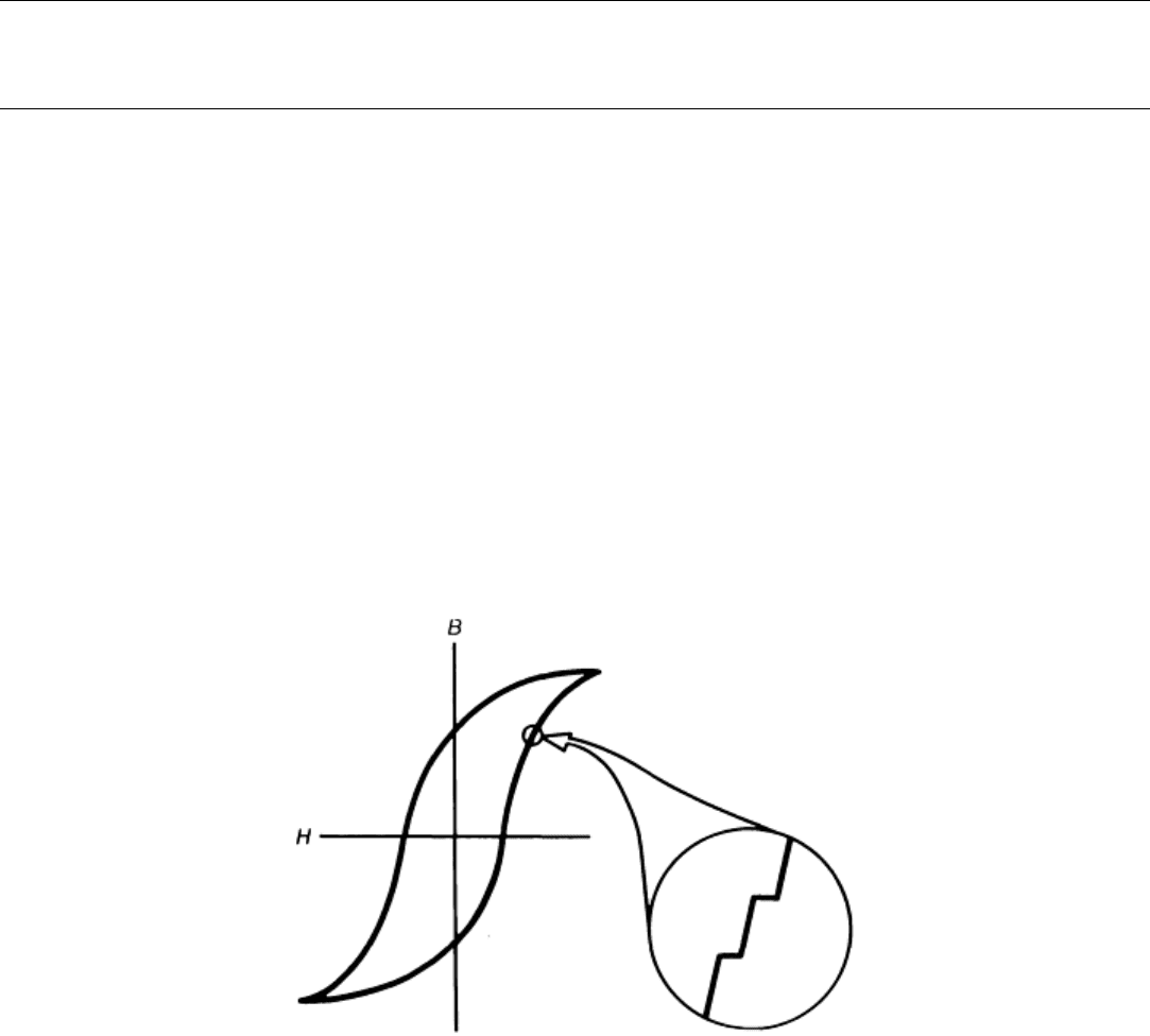
strictly continuous way, but rather by small, abrupt, discontinuous increments called Barkhausen jumps (after the name of
the researcher who first observed this phenomenon), as illustrated in Fig. 1. The jumps are due primarily to discontinuous
movements of boundaries between small magnetically saturated regions called magnetic domains in the material (Ref 7,
8, 9). An unmagnetized macroscopic specimen consists of a great number of domains with random magnetic direction so
that the average bulk magnetization is zero. Under an external magnetic field, the specimen becomes magnetized mainly
by the growth of volume of domains oriented close to the direction of the applied field, at the expense of domains
unfavorably oriented. The principal mechanism of growth is the movement of the walls between adjacent domains.
Because of the magnetoelastic interaction, the direction and magnitude of the mechanical stress strongly influence the
distribution of domains and the dynamics of the domain wall motion and therefore the behavior of Barkhausen jumps
(Ref 8). This influence, in turn, is used for stress measurements. Because the signal produced by Barkhausen jumps
resembles noise, the term Barkhausen noise is often used.
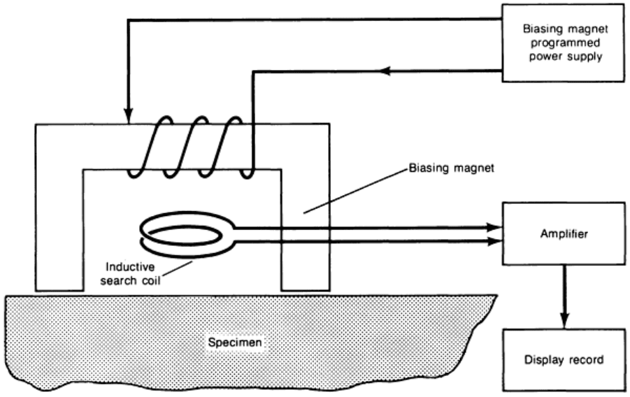
Fig. 1 Hysteresis loop for magnetic material showing discontinuities that produce Barkhausen noise.
Source:
Ref 2
Instrumentation. The arrangement illustrated in Fig. 2 is used for the Barkhausen noise technique (Ref 8). A small C-
shaped electromagnet is used to apply a controlled, time-varying magnetic field to the specimen. The abrupt movements
of the magnetic domains are typically detected with an inductive coil placed on the specimen. The detected signal is a
burst of noiselike pulses, as illustrated in Fig. 3. Certain features of the signal, such as the maximum amplitude or root
mean square (rms) amplitude of the Barkhausen noise burst or the applied magnetic field strength at which the maximum
amplitude occurs, are used to determine the stress state in the material (Ref 1, 8, 9, 10, 11, and 12).
Fig. 2 Arrangement for sensing the Barkhausen effect
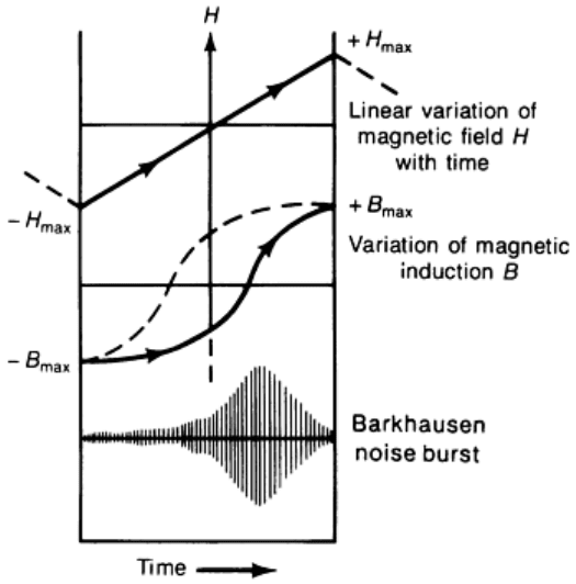
Fig. 3 Schematic showing the change in magnetic field H
with time, variation in flux density over the same
period, and the generation of the Barkhausen noise burst as flux density changes. Source: Ref 14
In addition to inductive sensing of the magnetic Barkhausen noise, magnetoacoustic Barkhausen activity can also be
detected with an acoustic emission sensor (Ref 13). This phenomenon occurs when Barkhausen jumps during the
magnetization of a specimen produce mechanical stress pulses in a manner similar to the inductive Barkhausen noise
burst shown in Fig. 3. It is caused by microscopic changes in strain due to magnetostriction when discontinuous,
irreversible domain wall motion of non-180° domain walls occurs (Ref 14, 15). This acoustic Barkhausen noise is also
dependent on the stress state in the material and can therefore be used for stress measurements (Ref 15, 16, 17, 18, and
19).
Stress Dependence. The magnetic Barkhausen effect is dependent on the stress as well as the relative direction of the
applied magnetic field to the stress direction. To illustrate this, Fig. 4 shows a typical stress dependence of the inductively
detected Barkhausen noise in a ferrous material. In the case where the magnetic field and the stress are parallel, the
Barkhausen amplitude increases with tension and decreases with compression (Ref 8, 10, 20, and 21). In the case where
the two are perpendicular, the opposite result is obtained. The behavior shown in Fig. 4 holds for materials with a positive
magnetostriction coefficient; for materials with a negative magnetostriction, the Barkhausen amplitude exhibits the
opposite behavior.
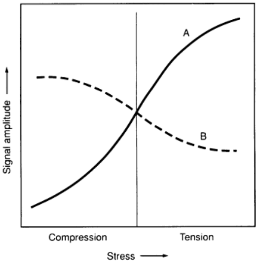
Fig. 4 Typical stress dependenc
e of Barkhausen noise signal amplitude with the applied magnetic field parallel
(curve A) and perpendicular (curve B) to the stress direction
For a given stress, the dependence of the Barkhausen amplitude on the angle between the magnetic field and stress
directions is proportional to the strain produced by the stress (Ref 21). Because the Barkhausen noise is dependent on the
strain, Barkhausen measurements can be used as an alternative to strain gages (Ref 20, 21).
A typical stress dependence of the acoustic Barkhausen noise is illustrated in Fig. 5, in which the magnetic field is applied
parallel to the stress direction. As shown, the amplitude of the acoustic signal decreases with tension. Under compression,
it increases slightly and then decreases with an increasing stress level. The acoustic Barkhausen noise, therefore, cannot
distinguish tension from compression.
