ASM Metals HandBook Vol. 17 - Nondestructive Evaluation and Quality Control
Подождите немного. Документ загружается.


These correlations between the signal amplitude and the interfacial area of the crack and between the peak-to-peak
separation and the surface length demonstrate that crack parameters can be obtained from signal features, thus
establishing the feasibility of crack characterization. The results were obtained with half-penny-shaped defects. However,
flaw characterization has also been demonstrated with other aspect ratios (Ref 3).
References cited in this section
1.
R.E. Beissner and M.J. Sablik, Theory of Electric Current Perturbation Probe Optimization,
Rev.Prog.
Quant. NDE, Vol 3A, 1984, p 633-641
3.
R.E. Beissner, G.L. Burkhardt, and F.N. Kusenberger, "Exploratory Development of Advanced Surface Flaw
Detection Methods," Final Report, Contract No. F33615-82-6-5020, Report No. AFWAL-TR-84-
4121,
Wright-Patterson Air Force Base, Sept 1984
6.
C.M. Teller and G.L. Burkhardt, Small Defect Characterization by the Electric Current Perturbation Method,
in Proc. of the Thirteenth Symposium on Nondestructive Evaluation,
Nondestructive Testing Information
Analysis Center, April 1981, p 443-453
Electric Current Perturbation NDE
Gary L. Burkhardt and R.E. Beissner, Southwest Research Institute
References
1. R.E. Beissner and M.J. Sablik, Theory of Electric Current Perturbation Probe Optimization,
Rev.Prog.
Quant. NDE, Vol 3A, 1984, p 633-641
2. F. Forster and H.L. Libby, Probe Coil-Detection of Cracks in Nonmagnetic Materials, in
Nondestructive
Testing Handbook, Vol 4, Electromagnetic Testing,
R.C. McMaster, P. McIntire, and M.L. Mester, Ed., 2nd
ed., American Society for Nondestructive Testing, 1986, p 185-187
3.
R.E. Beissner, G.L. Burkhardt, and F.N. Kusenberger, "Exploratory Development of Advanced Surface
Flaw Detection Methods," Final Report, Contract No. F33615-82-6-5020, Report No. AFWAL-TR-84-
4121, Wright-Patterson Air Force Base, Sept 1984
4.
C.M. Teller and G.L. Burkhardt, Application of the Electric Current Perturbation Method to the Detection
of Fatigue Cracks in a Complex Geometry Titanium Part, Rev. Prog. Quant. NDE, Vol 2B, 1983, p 1203-
1217
5.
C.M. Teller and G.L. Burkhardt, NDE of Fastener Hole Cracks by the Electric Current Perturbation
Method, Rev. Prog. Quant. NDE, Vol 1, 1982, p 399-403
6. C.M. Teller and G.L. Burkha
rdt, Small Defect Characterization by the Electric Current Perturbation
Method, in Proc. of the Thirteenth Symposium on Nondestructive Evaluation,
Nondestructive Testing
Information Analysis Center, April 1981, p 443-453
Electric Current Perturbation NDE
Gary L. Burkhardt and R.E. Beissner, Southwest Research Institute
Selected References
•
R.E. Beissner and G.L. Burkhardt, Application of a Computer Model to Electric Current Perturbation Probe
Design, Rev.Prog. Quant. NDE, Vol 4, 1985, p 371-378
• R.E. Be
issner, C.M. Teller, G.L. Burkhardt, R.T. Smith, and J.R. Barton, Detection and Analysis of
Electric-Current Perturbation Caused by Defects, in Eddy-
Current Characterization of Materials and
Structures, STP 722, F. Birnbaum and G. Free, Ed., American Socie
ty for Testing and Materials, 1981, p
428-446

•
G.L. Burkhardt and R.E. Beissner, Probability of Detection of Flaws in a Gas Turbine Engine Component
Using Electric Current Perturbation, Rev. Prog. Quant. NDE, Vol 4, 1985, p 333-341
• G.L. Burkhardt, F.N
. Kusenberger, and R.E. Beissner, Electric Current Perturbation Inspection of Selected
Retirement-For-Cause Turbine Engine Components, Rev.Prog. Quant. NDE, Vol 3, 1984, p 1377-1387
• G.L. Burkhardt, F.N. Kusenberger, R.E. Beissner, and C.M. Teller, Elect
ric Current Perturbation Inspection
of Complex Geometry Features in Gas Turbine Engine Components, in
Proc. of the Fourteenth Symposium
on Nondestructive Evaluation, Nondestructive Testing Information Analysis Center, April 1983, p 468-474
• G.L. Burkhard
t, G.W. Scott, and B.N. Ranganathan, Electric Current Perturbation Method for Inspection of
Aluminum Welds, Rev. Prog. Quant. NDE, Vol 5, 1986, p 1713-1721
• R. Palanisamy, D.O. Thompson, G.L. Burkhardt, and R.E. Beissner, Eddy Current Detection of Subsur
face
Cracks in Engine Disk Bolt Holes, Rev.Prog. Quant. NDE, Vol 3, 1984, p 643-651
Magabsorption NDE
William L. Rollwitz, Southwest Research Institute
Introduction
MAGABSORPTION TECHNIQUES were originated by the author at Southwest Research Institute in June 1957. During
electron spin resonance (ESR) measurements on a rocket propellant, it was noticed that an entirely different ESR signal
was obtained from the propellant with Fe
3
O
4
than from the same propellant without the iron oxide. When the microwave
power for the ESR was turned off but the modulation was left on, the different signal disappeared. When the modulation
power was turned off, the different signal also disappeared. Therefore, the signal appeared to depend not only on the
microwaves but also on the modulation. The frequency of the signal itself was predominantly a second harmonic of the
modulation frequency. When the magnetic field was varied from 0 to 0.4 T (4000 G), the ESR-type signal was obscured
by the different signal. The shape of the different signal did not change as the field varied from 0 to 0.4 T (4000 G), but
the amplitude did. The amplitude decreased almost linearly from 0.4 T (4000 G). The signal had the same shape but at a
much lower level as the field increased. The signal was obtained from the sample with iron oxide but not from the sample
without the Fe
3
O
4
. The same type of signal was obtained from a nuclear magnetic resonance (NMR) detector at 30 MHz
and from the ESR detector at 9240 MHz. When the modulation was stopped with the NMR and ESR detectors, the signal
disappeared.
It was concluded that the shape of this different signal was independent of the frequency used; it was a function of the
presence of Fe
3
O
4
, and it had a fundamental frequency that was twice the modulation frequency. When the signal was
observed before the amplitude detection in the NMR detector, it was found to be a 30-MHz carrier amplitude and/or
frequency modulated with the different signal whose fundamental frequency was twice the modulation frequency. The
phenomenon was not a resonance function of frequency. It was a function of the modulation field and was an amplitude
modulation of the radio-frequency (RF) signal used.
A schematic diagram of a system specifically made to detect the different signal is shown in Fig. 1. The sample of Fe
3
O
4
in Fig. 1 is in two alternating magnetic fields. The first is an RF field at 30 or 9240 MHz, and the second is a lower-
frequency field at 60 Hz. The peak value of the RF field, H
RF
is much lower than 8 A/m (0.1 Oe). The peak value of the
lower-frequency field is much higher at around 8000 A/m (100 Oe). The RF detection coil is resonated at the radio
frequency by the tuning capacitor in the NMR detector. The output of the NMR or ESR amplifier is the special signal
amplitude modulated on the RF voltage. The different signal is separated from the RF by an amplitude detector. Because
the shape of the different signal was found to be independent of frequency, a much lower frequency was used. For the
first detection system specifically made to detect the different signal, a frequency of 0.5 MHz was chosen as shown in
Fig. 1. An NMR-type detector was used at 0.5 MHz to detect the different signal.
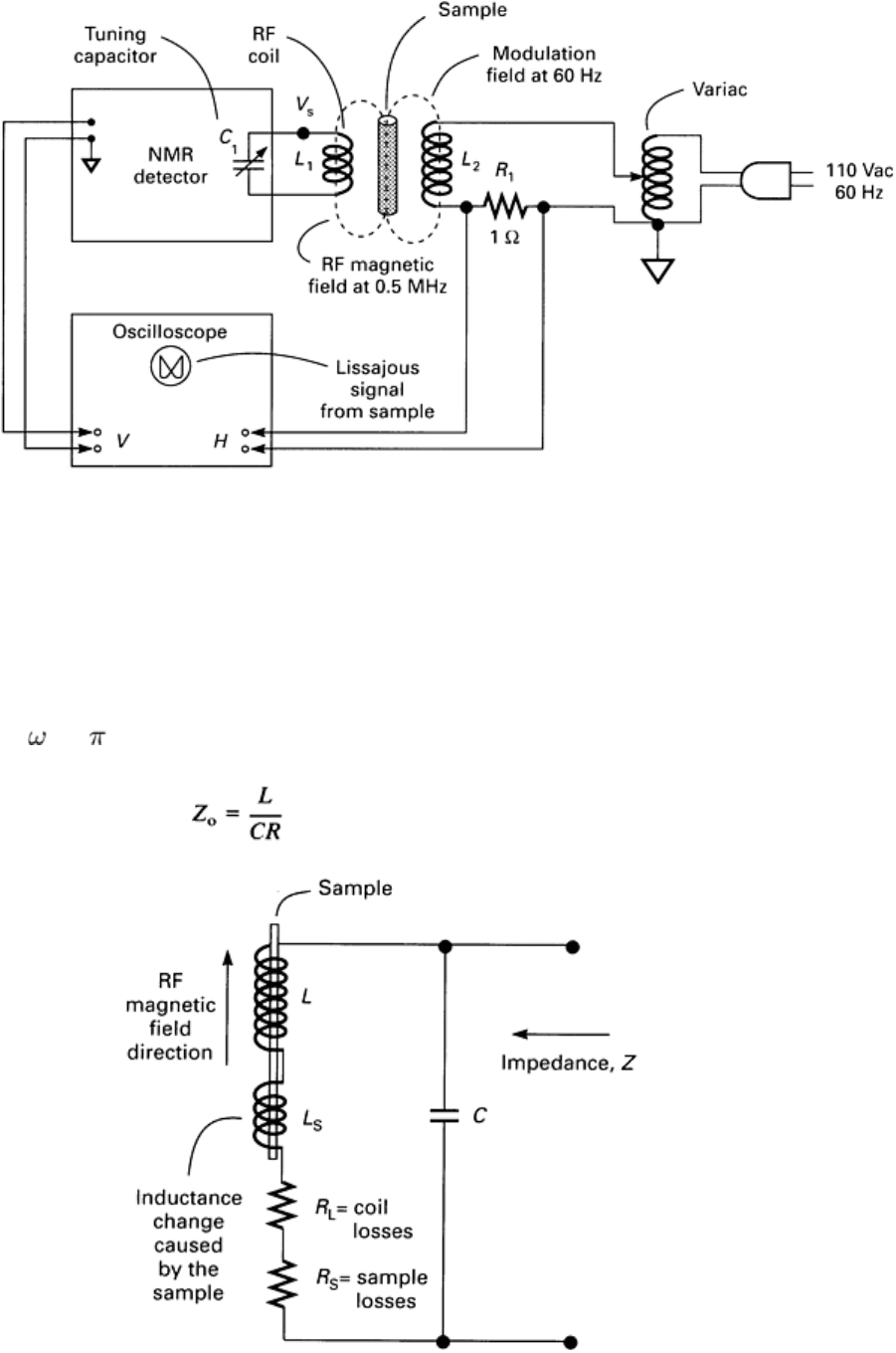
Fig. 1 Schematic of the special test system for the investig
ation of the detection of the different signal with an
NMR-type detector
The resonant circuit of the NMR-type detector can be represented by the diagram in Fig. 2. It is possible to use the
techniques used in nuclear magnetic resonance, which relate the very small changes in the energy absorbed by the nuclei
from the RF magnetic field as an amplitude modulation of the RF voltage V
s
across the RF coil in Fig. 2, where L is the
inductance of the RF coil, R
L
is the resistance representing the losses in the coil, and C is the capacitance required to tune
the circuit to
o
= 2 · 0.5 · 10
6
radians/s. The impedance, Z
o
, with no sample in the two fields, is:
(Eq 1)
Fig. 2 Resonant circuit showing the sample in the RF magnetic field
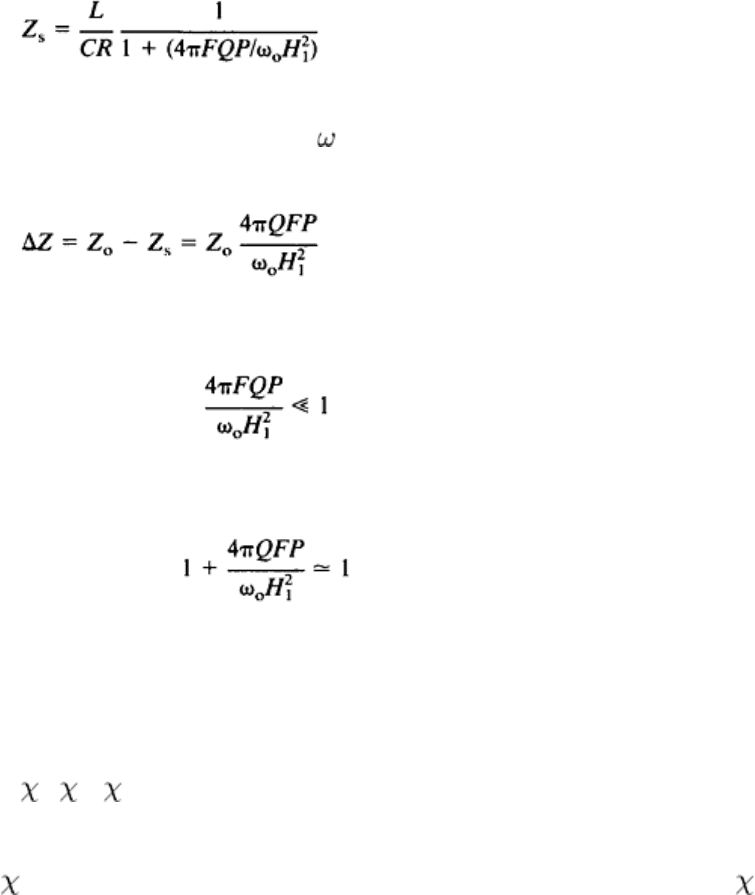
When there is a sample in the two magnetic fields, the impedance is changed to Z
s
, which is:
(Eq 2)
where F is the filling factor of the sample in the RF magnetic field, P is the power absorbed by the resonated nuclei
sample, Q is the figure of merit of the resonant circuit where Q =
o
L/R, and H
1
is the peak amplitude of the sinusoidal
RF magnetic field. The change of impedance caused by the power absorption by the sample is:
(Eq 3)
where
and
Equation 3 shows that the change in the resonant impedance of the detection circuit is directly proportional to the power
absorption (the rate of energy absorption) by the sample from the RF magnetic field. The nuclear magnetic resonance
signal is also directly proportional to the power absorbed by the chosen nuclei from an RF magnetic field. The RF power
absorbed by the nuclei is proportional to the complex susceptibility of the sample, which is:
= ' - ''
(Eq 4)
The power absorbed from the RF coil by the sample will therefore have two components--one in phase with the RF
magnetic field proportional to '' and a second one 90° out of phase with the RF magnetic field proportional to '. The
first is called the in-phase or absorption component of the NMR signal, and the second is called the quadrature-phase or
dispersion component of the signal. The different signal also has in-phase and quadrature-phase components. Therefore,
the different signal is directly proportional to the power absorbed by the susceptibility of the sample of iron oxide. The
susceptibility has both an in-phase component and a quadrature-phase component.
In October 1957, the author received funding for a program to study the phenomenon in more detail. Just before the
project was undertaken, it was found that W.E. Bell of Varian Associates had discovered a similar different signal. He had
termed the phenomenon magnetoabsorption and had written a paper with that title in 1956 (Ref 1). Bell attributed the
phenomenon to magnetoresistance and called it magnetoabsorption because the apparatus measures the RF absorption in
the test specimen as a function of the applied magnetic field.
The magnetoresistance phenomenon is described by Bozorth as the change in the electrical resistivity of iron when it is
magnetized (Ref 2). In most magnetic materials, this magnetoresistance is an increase of resistivity with magnetization
when the current and magnetization are parallel and a decrease when they are at right angles to each other; the change in
resistivity is independent of the sense of field or induction and, in this respect, is like magnetostriction (Ref 2). Reference
2 also gives the curve of Δρ/ρ as a function of the applied field strength; this magnetoresistance curve for nickel is shown
in Fig. 3. The magnetoresistance curve has a butterfly shape and hysteresis. The magnetoresistance change is 10 to 15%
of the resistivity at saturation, Δρ
s
. Reference 2 also states that the change in resistance (increase or decrease) is beyond
the knee of the magnetization curve.
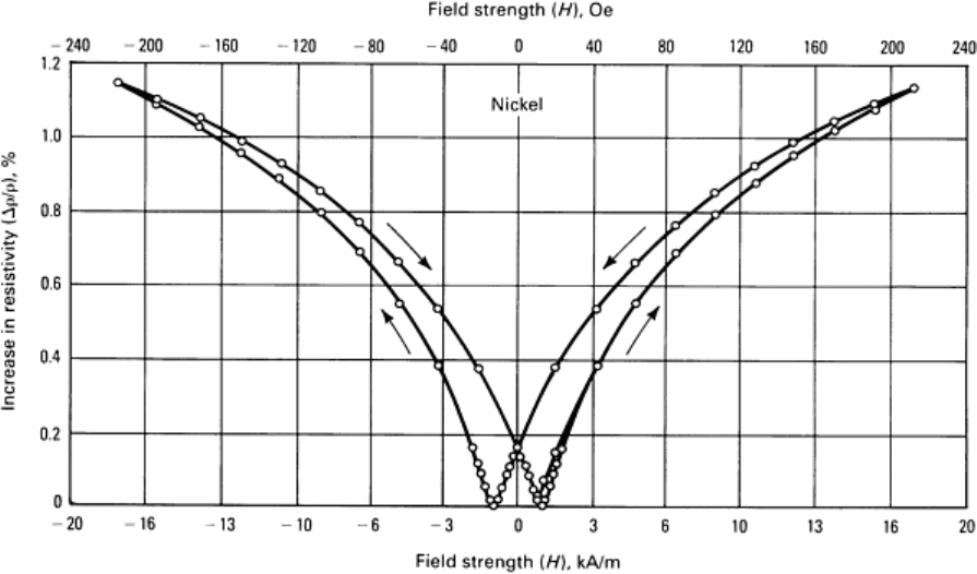
Fig. 3 Hysteresis of the magnetoresistance of nickel as plotted against applied field strength. Source: Ref 2
The effects of both tension and magnetic field on the resistivity of ferromagnetic materials are discussed in Ref 2 with the
aid of the domain illustrations in Fig. 4. According to Ref 2, domains having an initially haphazard distribution of
orientation (Fig. 4a) are aligned parallel by a strong (saturating) magnetic field (Fig. 4b). Tension applied to an
unmagnetized material, with positive magnetostriction, orients the domains along the axis of tension with one-half of the
domains antiparallel to the others (Fig. 4c). Because the resistivity depends on magnetization and increases with
increasing magnetization, each domain will contribute to the resistivity an amount depending on its orientation. This
contribution will be the same for parallel and antiparallel orientations; for the specimen as a whole, Δρ will be the same
for Fig. 4(b) and 4(c) and will be Δρ
s
. When the magnetostriction is negative, tension orients the domains at right angles
to the direction of tension, and the resistivity decreases (Fig. 4d). A magnetic field applied subsequently causes the
domains to rotate so as to increase the resistivity (Fig. 4e). When a material having positive magnetostriction is subjected
to strong tension, subsequent application of a magnetic field will cause 180° rotations (of the domains) almost
exclusively, and these will have no effect on resistivity (going from Fig. 4c to e).
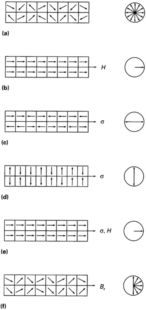
Fig. 4
Domain interpretation of the effects of field and tension on resistance. At right, domain vectors have
been moved to a common origin. (a) Unm
agnetized. (b) Saturated. (c) Tension applied (positive
magnetostriction). (d) Tension applied (negative magnetostriction).
(e) Tension and strong field. (f) Residual
induction
Because of the above discussion from Ref 2, the term magnetoabsorption was adopted by the author for the phenomenon,
and the internally sponsored work at Southwest Research Institute was undertaken using the title "Magnetoabsorption"
(Ref 3). However, the term magabsorption is now being used because the techniques have developed differently from the
magnetoabsorption described by Bell (Ref 1).
One of the magabsorption measurements described in Ref 3 involved measurements on iron carbonyl powders with a
bridge-type NMR detector. The in-phase or the loss component and the quadrature or the reactive component of the
magabsorption signal were separately detected and recorded. They were displayed as Lissajous figures where the
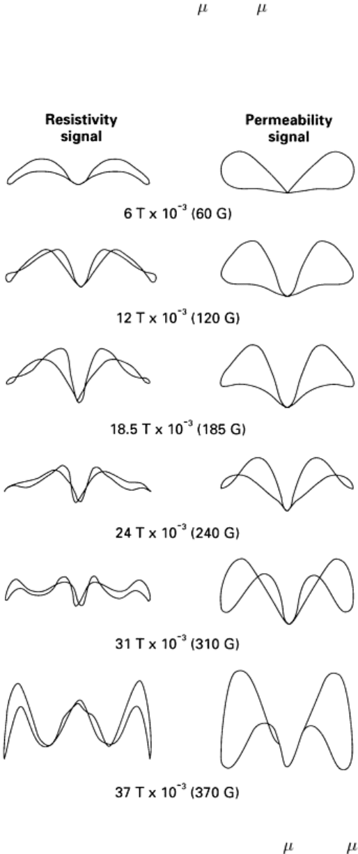
magabsorption signal (in-phase or quadrature-phase) was on the vertical axis of the oscilloscope and a voltage
proportional to the 60-Hz modulation was fed to the horizontal axis. The in-phase (resistive) and the quadrature-phase
(reactive) components of the magabsorption signals from a 3 m (120 in.) sample of carbonyl iron are shown in Fig. 5.
The shapes of the quadrature-phase signals are quite different from the in-phase signals in Fig. 5. The resistivity or the in-
phase signals have higher harmonic content than the quadrature-phase or reactive signals. Other results obtained during
the research summarized in Ref 3 are discussed in the section "Measurements and Applications" in this article.
Fig. 5 Comparison of resistivity and permeability components for a 3 m (120 in.) sample of iron carbonyl
The above discussion of the effect on the magnetoresistance caused by an applied magnetic field and an applied stress on
a piece of ferromagnetic material, coupled with the differences between the magabsorption signals from nickel powder
and nickel plating on a brass screw, led to the belief that magabsorption could be used to measure the stress and material
properties of ferromagnetic materials and nickel-plated nonferromagnetic materials. Research in this area was conducted,
and it resulted in four final reports (Ref 4, 5, 6, 7). This work is briefly described in this article, along with information
from Ref 8. Two patents have also been issued for this technology (Ref 9, 10).

References
1. W.E. Bell, Magnetoabsorption, Vol 2, Proceedings of
the Conference on Magnetism and Magnetic
Materials, American Institute of Physics, 1956, p 305
2. R.M. Bozorth, Magnetism and Electrical Properties, in Ferromagnetism, D. Van Nostrand, 1951, p 745-768
3. W.L. Rollwitz, "Magnetoabsorption," Final Report, Research Project No. 712-
4, Southwest Research
Institute, 1958
4.
W.L. Rollwitz and A.W. Whitney, "Special Techniques for Measuring Material Properties," Technical
Report ASD-TDR-64-123, USAF Contract No. AF-33(657)-10326, Air Force Materials Laboratory, 1964
5.
W.L. Rollwitz and J.P. Classen, "Magnetoabsorption Techniques for Measuring Material Properties,"
Technical Report AFML-TR-65-17, USAF Contract No. AF-33(657)-
10326, Air Force Materials
Laboratory, 1965
6. W.L. Rollwitz and J.P. Classen, "Magneto
absorption Techniques for Measuring Material Properties,"
Technical Report AFML-TR-66-76 (Part I), USAF Contract No. AF-33(657)-
10326, Air Force Materials
Laboratory, 1966
7. W.L. Rollwitz, "Magnetoabsorption Techniques for Measuring Material Properties.
Part II. Measurements
of Residual and Applied Stress." Technical Report AFML-TR-66-76 (Part II), USAF Contract No. AF-
33(615)-5068, Air Force Materials Laboratory, 1968
8. W.L. Rollwitz, Magnetoabsorption, Progress in Applied Materials Research, Vol 6, E.
G. Stanford, J.H.
Fearon, and W.J. McGonnagle, Ed., Heywood, 1964
9.
W.L. Rollwitz, Sensing Apparatus for Use With Magnetoabsorption Apparatus, U.S. Patent 3,612,968,
1971
10.
W.L. Rollwitz, J. Arambula, and J. Classen, Method of Determining Stress in Fe
rromagnetic Members
Using Magnetoabsorption, 1974
Magabsorption NDE
William L. Rollwitz, Southwest Research Institute
Magabsorption Theory
Magabsorption involves the measurement of the change in the energy absorbed from the field of an RF coil, by a
ferromagnetic material placed in the field of the coil, as a function of the strength of a magnetic bias field also applied to
the materials. The general concept of magabsorption is shown in Fig. 6. The ferromagnetic material is in both the RF
magnetic field of strength H
RF
and the bias magnetic field of strength H
B
. The value of H
RF
is much smaller than H
B
.

Fig. 6 General concept of magabsorption showing the RF field and the bias field in the material
A thorough understanding of the basic electrical and magnetic properties of ferromagnetic materials is essential to the
theoretical treatment of magabsorption. With these properties, a solution can be obtained that has correlated very well
with experimental measurements. However, because some of these properties are difficult to describe mathematically, an
exact solution is difficult if not impossible. Therefore, simplifying approximations are required to obtain a useful solution.
B-H Characteristics. When a magnetic field is applied to any material, a resulting magnetic flux density, B, is induced.
The intensity of the applied magnetic field is called the magnetic field intensity, H. The resulting flux density, B, is
directly proportional to the magnetic field intensity, H.
This relationship is normally written in the following form:
B = μH
(Eq 5)
The constant of proportionality, μ, is called the permeability, which may be nonlinear. When a ferromagnetic material is
subjected to a magnetic field, the flux density, B, is not a linear function of the magnetic field intensity, H. In other words,
the permeability, μ, is not a constant. In addition to this nonlinearity, the permeability depends on the past magnetic and
stress history of the ferromagnetic material. This dependence on past magnetic and stress history is known as hysteresis.
The hysteresis loop is explained by the concept of magnetic domains. Each domain consists of a group of atoms acting as
a small magnet. The group of atoms in a small region forms a small magnet because molecular interactions cause the
molecular magnetic moments to be aligned parallel to one another. In other words, each domain is spontaneously
magnetized to saturation even in the absence of an external magnetic field. Because the directions of magnetization in
different domains are not necessarily parallel to one another, the resultant magnetic flux density may be zero. When the
specimen is placed in a magnetic field, the resultant magnetic flux density can be changed by two different mechanisms.
The first is movement of a domain wall, and the second is directional rotation of the magnetic field of the domain. These
two domain processes must stop at a high magnetic field intensity because all the domains become aligned with the
applied magnetic field. This limiting process causes the nonlinearity of the B-H characteristics. Also, the stability of
different domain orientations causes the hysteresis of the B-H characteristics. Therefore, the shape of the hysteresis loop
and the domain orientation are dependent on the type of material, its stress history, and its magnetic history.
Reversible Permeability. If at some point on the hysteresis loop the magnetic field intensity is reversed from its
normal direction, the resulting magnetic flux density will not follow the original hysteresis loop. This deviation from the
original hysteresis is explained by the concept of the domain. If the magnetic field intensity is decreased before it reaches
the previous limit, the orientation stability of the domain will cause hysteresis.
If the deviation of the magnetic field intensity is a small cyclic field, ΔH, super-imposed on a large bias field, H
B
then a
smaller inner hysteresis loop will be formed, as shown in Fig. 7. Note that the magnetic biasing field, H
B
, is the magnetic
field that determines the larger external hysteresis loop. As the size of the small cyclic deviation in the magnetic field
intensity, ΔH, is decreased, the resulting change in the magnetic flux density, ΔB, is decreased. As ΔH approaches zero,
the ratio ΔB/ΔH approaches a limiting value μ
o
μ
r
:
(Eq 6)
where
o
is the permeability of free space (in henries/meter),
r
, is the relative reversible permeability (unitless), and is
the reversible permeability (in henries/meter).
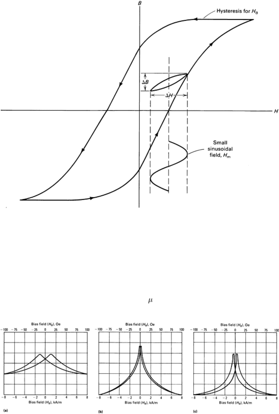
Fig. 7 Superimposed hysteresis loops
The reversible, or alternating current (ac), permeability is the property of great interest in the study of magabsorption.
Reversible permeability is dependent on the reversible boundary displacement and reversible rotation of the domains in
the ferromagnetic material. Therefore, the reversible permeability is dependent on the type of material and its magnetic
and stress history. The relative reversible permeabilities for unannealed nickel, annealed nickel, and iron are shown in
Fig. 8. For all the relative reversible permeability curves in Fig. 8, the upper portion of the curve is observed for an
increasing bias field, and the lower portion of the curve is observed for a decreasing bias field. Assuming that the
ferromagnetic material was originally demagnetized, the plot of
r
versus H
B
is symmetrical about H
B
= 0.
Fig. 8
Relative reversible permeability curves for (a) unannealed nickel wire, (b) annealed nickel wire, and (c)
iron thermocouple wire
