ASM Metals HandBook Vol. 17 - Nondestructive Evaluation and Quality Control
Подождите немного. Документ загружается.

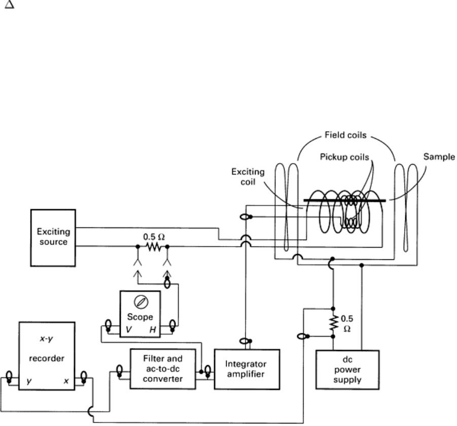
A block diagram of an apparatus used to measure relative reversible permeability is shown in Fig. 9. A small cyclic
deviation, H, in the magnetic field intensity was generated with an exciting coil. The change in the magnetic flux
density was detected with two identical pickup coils. The two pickup coils were connected so that the sum of their output
voltages would be determined by the derivative of the difference in the magnetic flux in the two coils. If a sample is
placed in one of the pickup coils, the output voltage is directly proportional to the derivative of the magnetic flux in the
sample. Using an electronic integrator to integrate the output voltage of the two pick-up coils, a voltage is obtained that is
directly proportional to the magnetic flux in the sample. The output voltage of the integrator was displayed versus the
cyclic deviation in the magnetic field intensity on an oscilloscope. The resulting oscilloscope display is the smaller inner
hysteresis loop shown in Fig. 7. A biasing magnetic field was applied with the use of larger field coils.
Fig. 9 Block diagram for relative reversible permeability apparatus
If the cyclic deviation in the magnetic field intensity, ΔH, is held constant in magnitude, the cyclic deviation in the
magnetic flux density, ΔB, is directly proportional to the relative reversible permeability, μ
r
. The output of the integrator
can be converted to dc voltage with an ac-to-dc converter, which can be displayed on an x-y recorder versus the biasing
magnetic field, H
B
.
The Magabsorption Phenomenon. The basic arrangement of magabsorption measurements is shown in Fig. 6.
When H
B
varies slowly in the material and B is plotted as a function of H, the B/H hysteresis loop of Fig. 10 is obtained.
If H
B
is applied sinusoidally, the B/H curve will be repeated at the same rate, and B is not only distorted in the shape
relative to the sinusoidal magnetomotive force but also shifted in phase. As the frequency of H
B
increases, both the
distortion in shape and the shift in phase increase. If another magnetomotive force, H
RF
, of smaller magnitude and higher
frequency is added to the material (Fig. 6), there will be a second B
RF
/H
RF
loop for the material. This second hysteresis
loop is shown at one value of H
B
in Fig. 10. As H
B
varies through one sine wave, the magnitude and phase of B
RF
also
change. If the RF permeability, B
RF
/H
RF
= μ
RF
, is graphed as a function of H
B
, the curve in Fig. 11 is obtained. This RF
permeability hysteresis curve is also a function of the frequency and the amplitude of the magnetomotive force, H
B
.
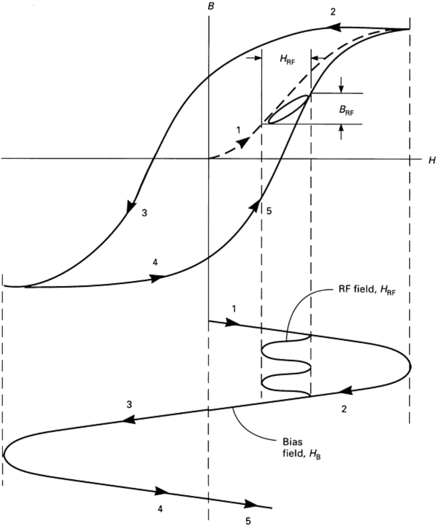
Fig. 10 Hysteresis loops of the material under two magnetomotive forces, H
B
and H
RF
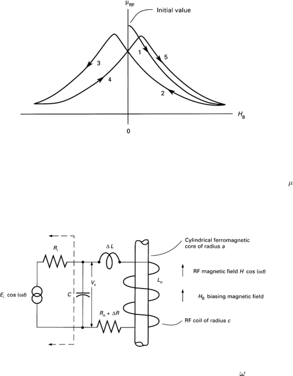
Fig. 11 RF permeability as a function of the alternating magnetomotive force, H
B
, at a fixe
d value of the RF
magnetomotive force, H
RF
. The numbers on the curves correspond to numbers on the curve of H
B
in Fig. 10.
The variation in μ
RF
as a function of H
B
is the basis for the magabsorption phenomenon. Because the RF permeability,
RF
, changes as H
B
is varied sinusoidally, the energy absorbed by the material from the RF coil also varies as a function of
H
B
. These variations in the absorption of RF energy by the material can also cause changes in the impedance of the RF
coil. For example, if a cylindrical sample is placed in the coil as shown in Fig. 12, the change in coil impedance, ΔZ, is
related to the energy absorbed, according to Eq 3.
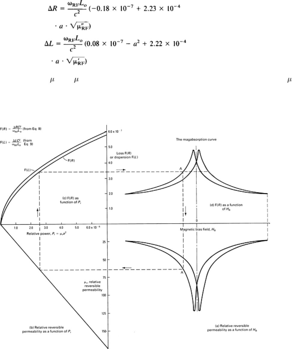
Fig. 12 Basic magabsorption circuit composed of an inductance, L, with the sample core in a biasing field, H
B
,
and tuned to resonance with capacitance C. The circuit is fed from an RF voltage e
i
, = E
i
cos ( t)
The variations in coil impedance from magabsorption involve a resistive change, ΔR, and a change in inductance, ΔL.
Both of these changes can be related to the RF permeability, μ
RF
. Because the RF hysteresis loop has a shape other than a
straight line (that is, an ellipse), if H
RF
is H
RF
exp iωt, the RF induction is B
RF
exp i(ωt + θ). Therefore, the RF
permeability is a complex variable:
μ
RF
= μ'
RF
+ iμ''
RF
(Eq 7)
where μ''
RF
is the loss (ΔR) term and μ''
RF
is the dispersion (ΔL) term. For a cylindrical sample of radius a and a coil of
radius c as shown in Fig. 12, the solution of the Maxwell equations resulted in the following normalized values of ΔR and
ΔL for a ferromagnetic material (Ref 4):
(Eq 8)
(Eq 9)
where c is larger than a and '
RF
and ''
RF
are functions of the bias field H
B
. Because there is no simple equation for
RF
as a function of H
B
(Fig. 11), the shape of ΔR and ΔL is most easily obtained graphically, as shown in Fig. 13. The
resultant curve, in the top right-hand corner, is either the magabsorption amplitude signal of the loss (ΔR) component or
the dispersive (ΔL) component.
Fig. 13 Graphical derivation of the magabsorption curve from the permeability and F(R) and F(L) curves
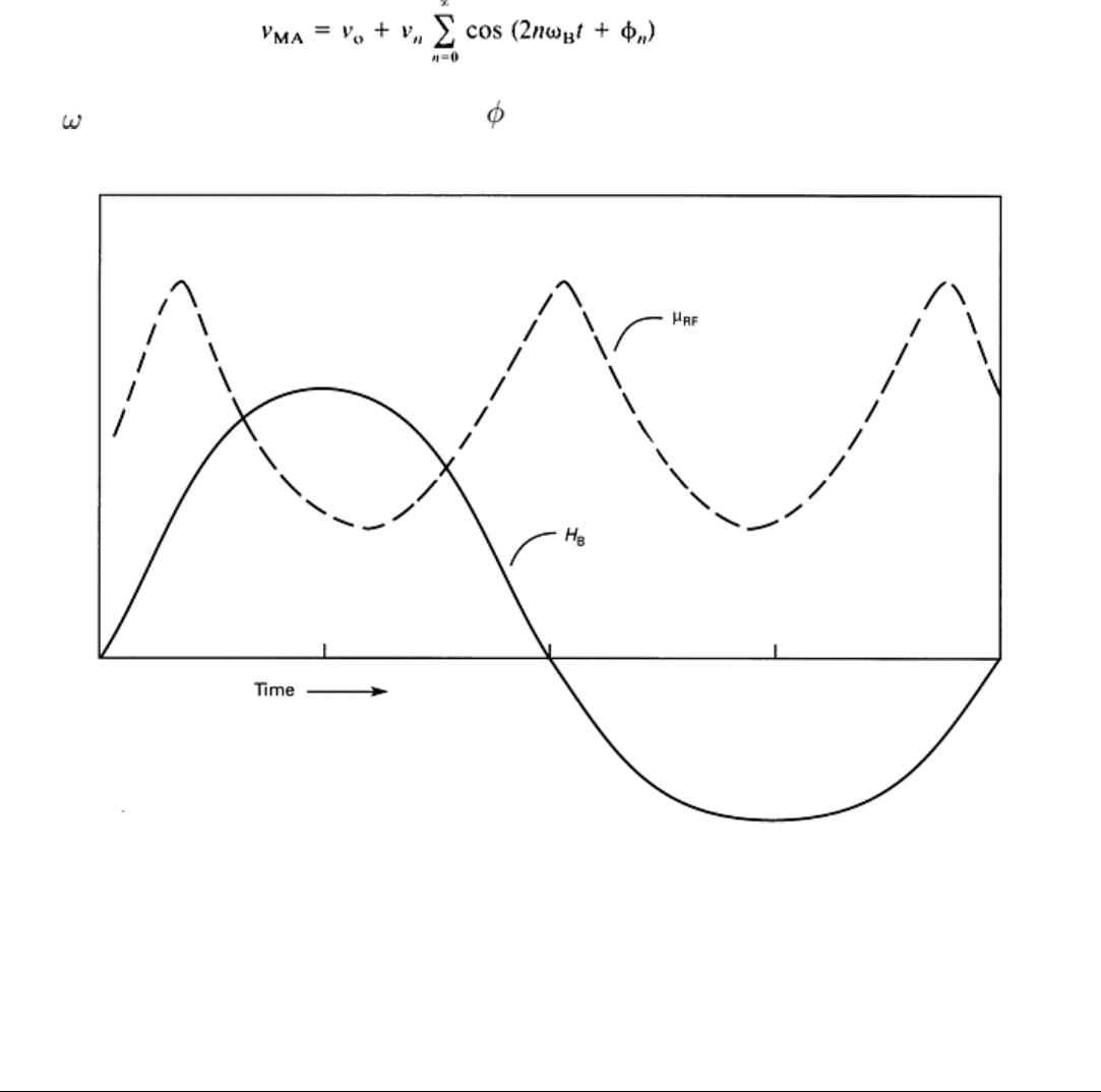
Therefore, the variations in the absorption of RF energy by the material produce a magabsorption signal, which causes the
resistance and inductance of the RF coil to change. The basic or fundamental frequency of the magabsorption signal is
twice that of the magnetic bias frequency. If H
B
has a frequency of 60 Hz, the magabsorption signal has a basic frequency
of 120 Hz. However, because the magabsorption signal is not a pure sinusoid (Fig. 14), the entire frequency content of the
magabsorption signal has harmonics of the basic frequency. Therefore, the magabsorption signal, v
MA
, is:
(Eq 10)
where
B
is the magnetic bias angular frequency and
n
is the phase angle of the harmonic order, n.
Fig. 14 Time plot of H
B
and μ
RF
. Although the shape of μ
RF
is distorted relative to a sinusoid, the basic frequency
of μ
RF
is twice that of H
B
.
A more extensive derivation of the magabsorption signal is discussed in a report of work done for the Air Force Materials
Laboratory in Dayton, OH (Ref 4). It was from this report that Eq 8 and 9 were obtained.
Reference cited in this section
4.
W.L. Rollwitz and A.W. Whitney, "Special Techniques for Measuring Material Properties," Technical
Report ASD-TDR-64-123, USAF Contract No. AF-33(657)-10326, Air Force Materials Laboratory, 1964
Magabsorption NDE
William L. Rollwitz, Southwest Research Institute
Magabsorption Detection
The phenomenon of magabsorption changes the resistance and inductance of the RF coil, which causes the modulation of
the RF voltages in the circuit shown in Fig. 6. The RF voltage across the resonant circuit is amplitude modulated by the
change in resistance of the coil and is phase or frequency modulated by the change in inductance of the coil. Of course,
there is a small additional amplitude modulation caused by the phase modulation. Therefore, if the voltage across the
resonant circuit of Fig. 6 is demodulated through both an amplitude detector and a phase detector using a voltage,
proportional to the bias current, as a reference signal, the magabsorption amplitude signal is obtained from the amplitude
detector, and the magabsorption frequency signal is obtained from a phase or frequency detector.
If the voltage generator e
s
and the resistance R
S
are those of a self-sustained oscillator, the voltage across the resonant
circuit is amplitude modulated by means of the magabsorption amplitude signal, and the frequency of oscillation will be
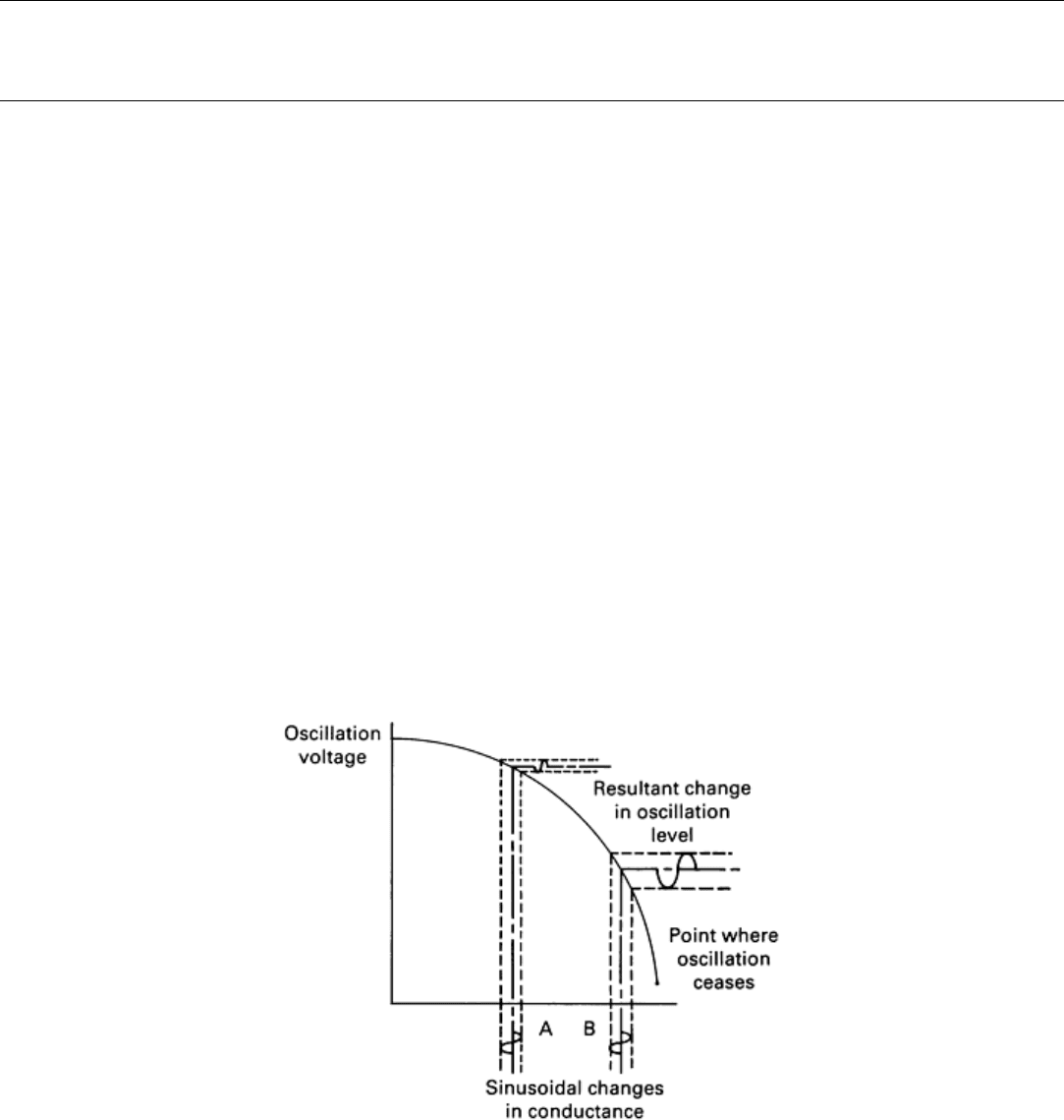
modulated by the magabsorption frequency signal. If the oscillator is operated at a high level of output (A, Fig. 15), the
detection sensitivity will be weak for the amplitude modulation. When the oscillator is operated at its marginal point or
the point close to where oscillations cease (B, Fig. 15), the slope for the voltage change as a function of resistance change
in the coil is very large, and the voltage across the resonant circuit is highly modulated by the magabsorption amplitude
signal. Because the resonant circuit alone controls the frequency, the frequency modulation is relatively independent of
the oscillation level. It will be true, however, that at the high levels of oscillation the effective Q of the RF coil will be
low, and the amplitude modulation of the oscillator output by the magabsorption amplitude signal will be reduced. Under
this condition, the amplitude modulation caused by the frequency modulation will be reduced.
Fig. 15 Oscillation voltage as a function of the resonant circuit conductance. A, operat
ion point for low
sensitivity; B, operation point for high sensitivity
The amplitude modulation of the RF signal by the magabsorption signal in Fig. 13 has a fundamental frequency and
harmonic frequency components at twice the frequency of the bias field. If ω
B
is the bias field frequency, the
magabsorption signal frequencies are at 2ω
B
, 4ω
B
, 6ω
B
, and so on. If ω
RF
is the frequency of the RF field in Fig. 6, the
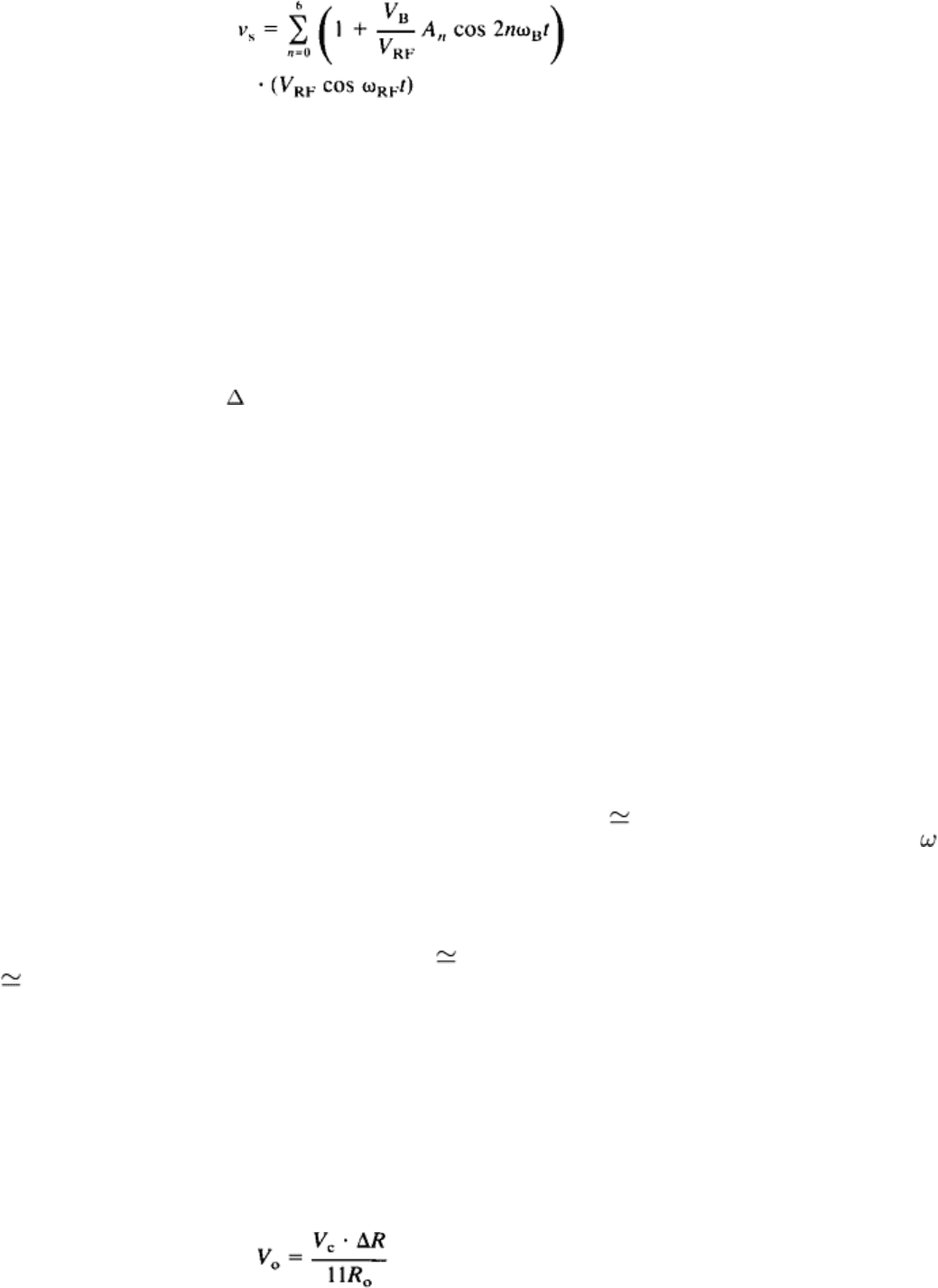
equation for the modulated RF signal, v
s
, across the resonant LC circuit in Fig. 6 is:
(Eq 11)
where V
B
and V
RF
are the peak amplitudes of the bias and RF fields and A
n
is a multiplier to give the amplitude of the n
th
harmonic of the magabsorption signal.
With a marginal oscillator as a magabsorption detector, the magabsorption amplitude signal can be obtained with an
amplitude modulation detector. The magabsorption frequency signal, however, will be obtained with a frequency
discriminator or similar frequency demodulator. Both of these voltages from the demodulators will be similar in shape to
the magabsorption curve, and they will be nearly of equal amplitude for the same or similar demodulator constants.
Further, each signal can be described by a Fourier series, as indicated in Eq 10.
General Detection Methods. The magabsorption signal as modulation on a carrier can be detected in three ways.
First, the modulated carrier can be amplified and the modulation recovered by a diode detector, a coherent detector, or a
mixer. This would yield the R component of the magabsorption signal.
In the second method, a receiver or narrow-band amplifier is set to one or more of the sideband frequencies, and the
amplitude of that sideband is detected by amplitude demodulation. For example, if the bias frequency, f
B
, is 80 Hz and the
RF frequency, f
RF
, is 10 kHz, the magabsorption modulated carrier will have components at 10,160, 10,320, 10,480,
10,640, 9840, 9680, 9520, and 9360 Hz if the magabsorption signal contains only four harmonics. Therefore, the presence
of a magabsorption signal could be detected by a narrow-band amplifier tuned to any one of the frequencies given above.
Because the 10,160 Hz and 9840 Hz components are the strongest, they will provide the most sensitive detection.
The third method is to amplify the voltage across the resonance circuit and to detect the frequency modulation. This
would give the ΔL component of the magabsorption signal. The amplitude demodulation (the first method) gives a
mixture of both the ΔR and the ΔL components of the magabsorption signal. In most cases, however, the ΔR component is
much larger than the ΔL component because the frequency modulation (ΔL) causes only a small amplitude modulation
relative to that caused by ΔR.
The basic magabsorption circuit used with the cylindrical sample of radius a is shown in Fig. 12. The magabsorption
phenomenon causes a change in both the resistance, ΔR, and the inductance, ΔL, of the magabsorption detection coil.
These variations change the coil impedance, Z
c
, by an amount ΔZ such that Z
c
= ΔZ + Z
o
. The magnitude of the voltage
across the parallel resonant circuit at resonance is V
c
= (L/RC)I
c
, where I
c
(E
i
/R
i
) cos (ωt), because R
i
is much larger
than Z
c
. For all magabsorption measurements, a high-Q coil is used. A high-Q coil is defined as one in which Q = ( L/R)
> 10.
For magabsorption measurements on wire, the filling factor, F, which is the ratio of the volume of the wire sample to the
volume inside of the RF coil, is less than 0.01. This value of the filling factor keeps the loaded Q of the coil also greater
than 10. The theoretical derivation has shown that ΔR ωΔL. Taking into account the above assumptions and because R
i
10 L
o
/R
o
C and ΔR is less than 0.1 R
o
, the voltage change, ΔV, can be approximated within 1% to be directly
proportional to the ΔR from magabsorption. The change in resonant frequency can also be shown to be directly related to
ΔL.
The Magabsorption Bridge Detector. The voltage across the resonant RF circuit in Fig. 12 is V
c
+ ΔV. Although the
actual value is approximately 0.1 E
i
, there may be problems in amplifying V
c
+ ΔV because of the dynamic range of many
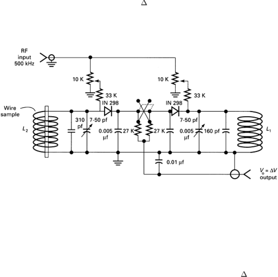
amplifiers. Therefore, the bridge circuit in Fig. 16 has been used to eliminate V
c
and to give an output of only ΔV. The left
resonant circuit contains the material sample, while the right resonant circuit contains no sample. The rectified voltages
across each resonant circuit are detected, subtracted, filtered, and supplied to the output. With no magabsorption signal,
the output is zero. With a magabsorption signal, the output of the bridge in Fig. 16 is:
(Eq 12)
The magabsorption bridge is used when the variation rate for R is very low (<0.1 Hz). At low variation rates, the output
is very stable with changes in time, temperature, and input voltage. The use of the bridge reduces stringent requirements
on the amplitude stability and the frequency stability of the source for the input to the bridge at 500 kHz. This bridge was
used for all of the earliest magabsorption measurements.
Fig. 16 Magabsorption measurement RF bridge, in which the peak value of two similar simp
le circuits are
subtracted to give the magabsorption signal
When the bias field is changed or varied, the bridge must be rebalanced for each sample unless a complicated automatic
balancing circuit is used. The need to rebalance the bridge can be eliminated if the resonant circuit in Fig. 12 is the
resonant circuit of an oscillator.
The Marginal Oscillator Magabsorption Detector. Figure 17 shows the schematic of the circuit when the RF coil
is part of an active oscillator circuit. This type of circuit can also be used to detect the R component of the
magabsorption signal. This detection will occur only if the oscillator is made to operate as close to Class A or linear
conditions as possible. As such, it will be an efficient magabsorption detector.
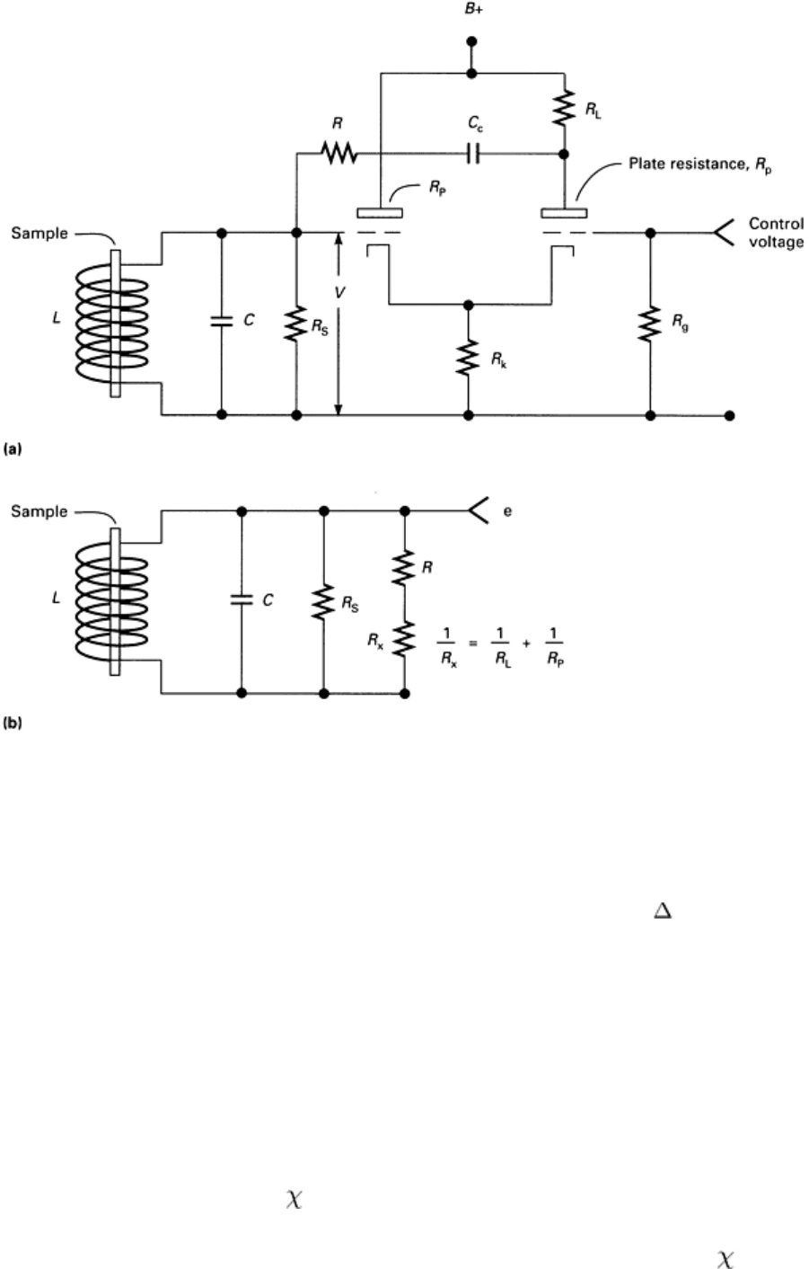
Fig. 17 Marginal oscillator basic circuit (a) and equivalent circuit (b)
The detector illustrated in Fig. 17 is called a marginal oscillator because it is operated on the edge of dropping out of
oscillation. The presence of a magabsorption sample in the RF coil will change both the series resistance and the
inductance of the coil. Instead of ΔL changing only the resonant frequency of the RF coil, L changes both the driving
frequency of the oscillator and the resonance frequency of the RF coil by the same amount. Therefore, the resonant
frequency of the coil and the frequency fed to the RF coil are the same. They are locked together because the RF resonant
circuit controls both. In this way, it is possible to measure the effect of the sample both on the losses from the coil and the
inductance of the coil. As stated previously, the losses change the amplitude of the oscillation, while the dispersion
changes the oscillation frequency.
For an analysis of the effects of the magabsorption phenomenon on a marginal oscillator, assume that the ratio of the
radius of the sample to the radius of the RF coil is such that the effect of the sample is small compared to the magnitudes
of the coil inductance and effective resistance. The sample effect will therefore be more like that of a paramagnetic
material. The inductance of the coil shown in Fig. 12 or 17 can then be written as:
L = L
o
(1 + F )
(Eq 13)
where L
o
is the inductance without the sample, F is the filling factor of the coil-sample system, and is the susceptibility
of the sample. The susceptibility is usually defined for only diamagnetic or paramagnetic substances by the relation:
B = μ
o
H(1 + χ)
(Eq 14)
where χ= χ' - iχ; χ'' is the loss term and χ' is the dispersion term.
For paramagnetic materials, the susceptibility is of the order of 10
-4
to 10
-6
. For ferromagnetic materials, the susceptibility
may be many orders of magnitude larger. However, the susceptibility seen by the RF coil is very small when the filling
factor (volume of the core divided by the volume of the coil) for the ferromagnetic core is kept small. Therefore, Eq 14
can be written as:
B = μ
o
H(1 + Fχ)
(Eq 15)
when the filling factor F is considered. The filling factors used are in the range of 10
-3
to 10
-4
. Therefore, the
ferromagnetic core material with a large susceptibility and a small filling factor can have the same effect as a
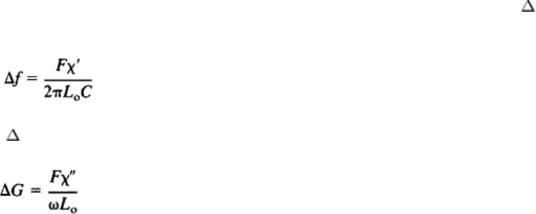
paramagnetic material with a small susceptibility and a unity filling factor. With this approach, the frequency shift, f, of
the oscillator with a sample in the coil is:
(Eq 16)
and the change in conductance, G, of the resonant circuit is:
(Eq 17)
To keep the resonance condition, then, the frequency must be changed by the factor Δf (Eq 16). If this change in
frequency is accomplished automatically by making the resonant circuit the frequency-controlling circuit of an oscillator,
ΔG can be measured by determining its effect on the impedance of the resonant circuit. The value of Δf can be obtained
by measuring the frequency shift of the oscillator. With ΔG and Δf, the values of χ'' and χ' can be calculated and related to
the material of the sample inserted in the coil and to the effects of the magnetic bias field.
When the resonant circuit illustrated in Fig. 17 undergoes an impedance change from any variation of χ'', the change in
conductance (Eq 17) will result in a change in the voltage across the resonant circuit. If the value of ΔG is much smaller
than 1/R
S
of the circuit in Fig. 17(b) and if the first approximation of linearity is assumed, then the voltage change in the
oscillator can be shown to be directly proportional to the conductance change caused by the sample. Moreover, if the
conductance change, ΔG, is sinusoidal, a phase change is introduced that will shift the phase of the sidebands relative to
the oscillation frequency. Figure 18 shows the block diagram of a system for measuring ΔG versus the voltage change in
the oscillator.
