ASM Metals HandBook Vol. 17 - Nondestructive Evaluation and Quality Control
Подождите немного. Документ загружается.

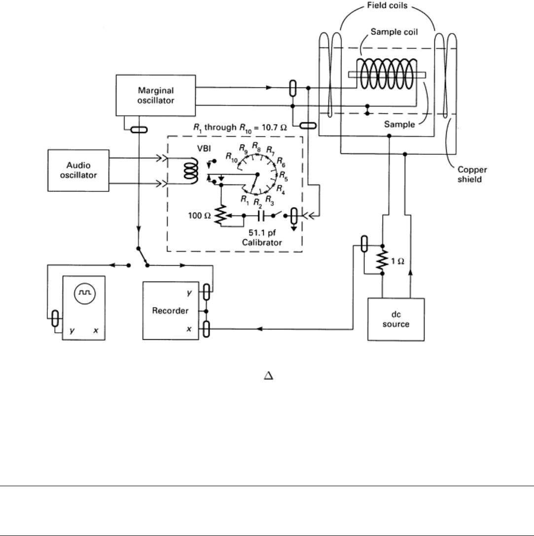
Fig. 18 Block diagram of the system for measuring G versus the voltage output of a marginal oscillator
It is also interesting to compare a marginal oscillator with the passive resonant circuit of Fig. 12. The effective gain of the
oscillator circuit over the passive circuit can range from 5 to 10 with readily attainable values of circuit constants. The
oscillator produces a gain over that of the passive system by decreasing the bandwidth or by increasing the effective
quality factor. Because the signal is amplified and detected in both cases, the marginal oscillator offers a gain advantage
that may improve the signal-to-noise ratio.
Magabsorption NDE
William L. Rollwitz, Southwest Research Institute
Measurements and Applications
The basic method of magabsorption measurement requires a ferromagnetic material that is excited by both an RF
magnetic field and another magnetic field with a lower frequency and a much higher field strength. This basic
arrangement is shown in Fig. 19 with a stressed wire placed inside the RF coil. Magabsorption measurements can also be
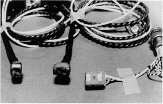
performed with magabsorption detection heads (Fig. 20) that are placed on the surface of a specimen.
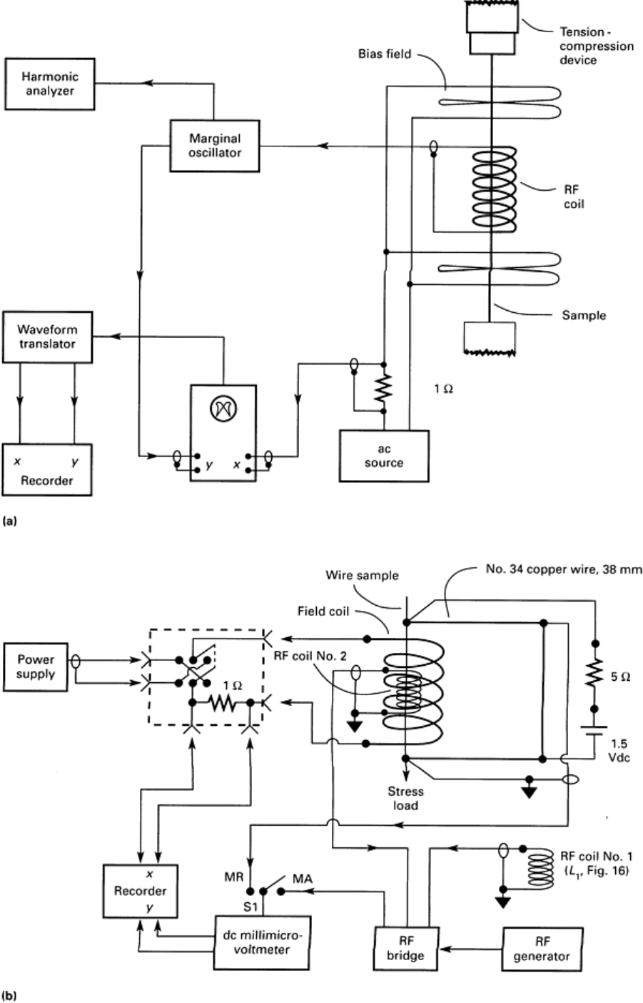
Fig. 19 Two arrangements for measuring
magabsorption signals. (a) Block diagram of system with a marginal
oscillator for measuring the harmonic content. (b) Block diagram of a system with a bridge detector. Switch S1
connects the circuit for either magnetoresistance (MR) measurements or magabsorption (MA) measurements.
Fig. 20 Closeup view of three detection heads used with magabsorption measurements on a crankshaft
throw.Left, head for perpendicular measurements in fillets; middle, head for parallel measurements in fillets;
right, head for all measurements in areas having a large radius of curvature
In the work discussed in Ref 3, 4, 5, 6, and 7, magabsorption measurements were performed on various materials in
different applications. Some of the magabsorption signals from a variety of materials are given in Fig. 21. The potential
applications of magabsorption measurements, which are described in more detail in the following sections, include:
•
Magabsorption measurements on ferromagnetic and ferrimagnetic powders, along with a particle size
effect in the magabsorption measurements of the powders that might b
e used to determine the size or
range of particles
•
Magabsorption measurements of applied and residual stress in ferromagnetic materials or
nonferromagnetic materials having a ferromagnetic coating
• Magabsorption measurements of residual magnetism in ferro
magnetic and nonferromagnetic materials
(such as some stainless steels) in which the yield point or phase transition temperature has been
exceeded
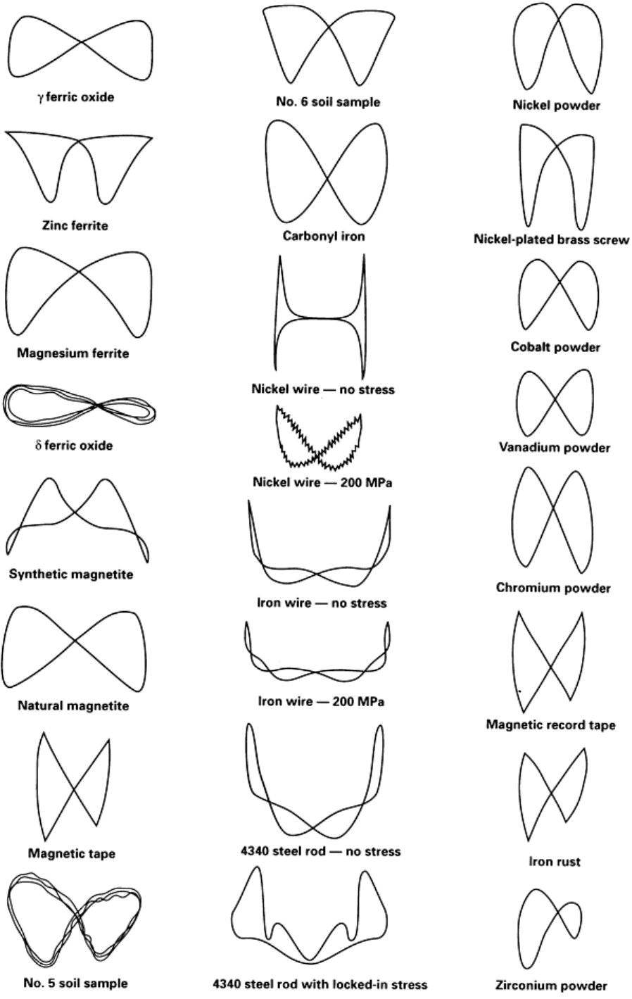
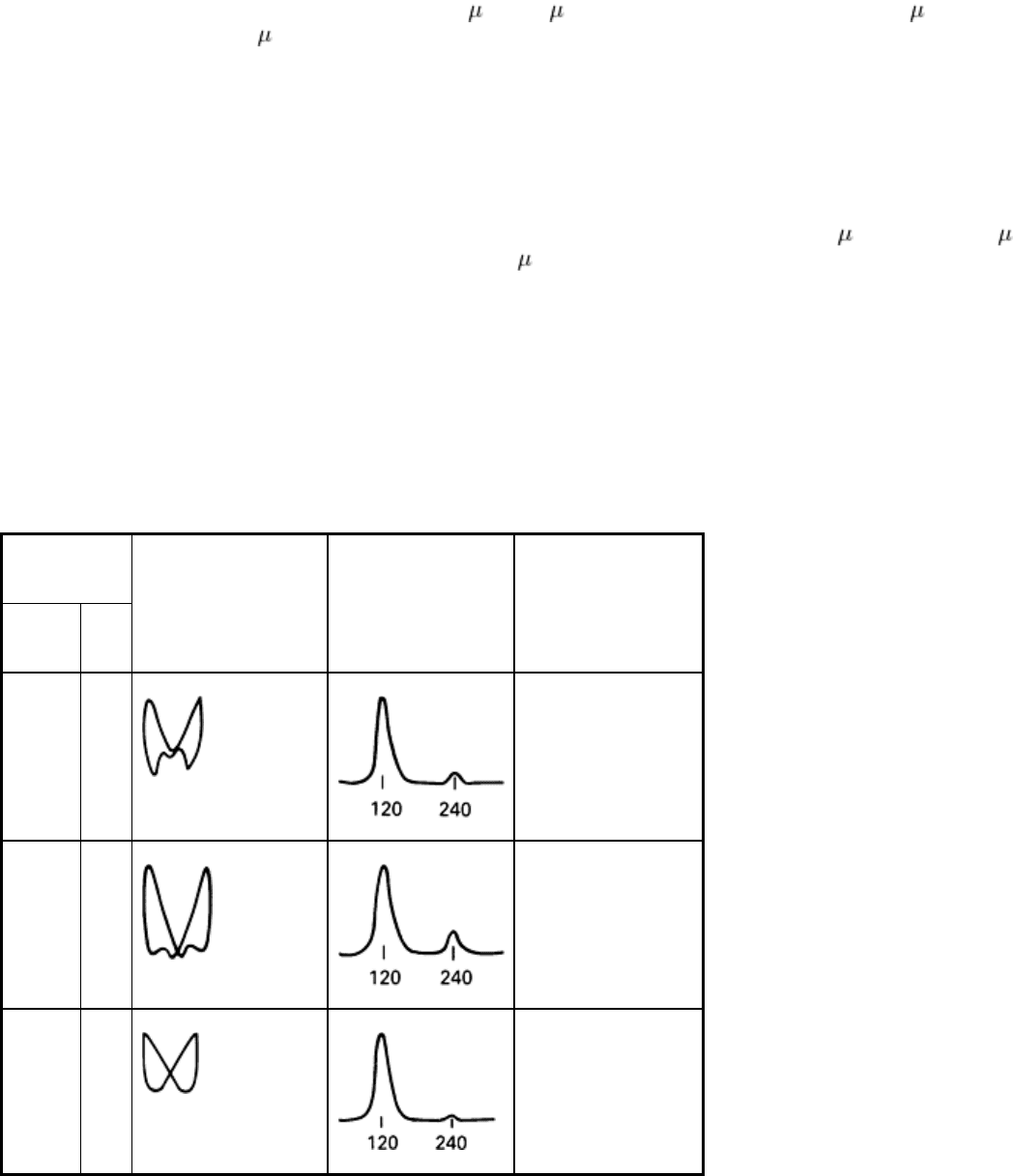
Fig. 21 Magabsorption signals from various materials
Magabsorption Measurements of Powders
The first magabsorption measurements were made using iron oxide and iron carbonyl (Ref 3). The first measuring
instrument was a Q-meter made by Boonton. When a sample is inserted into the coil, the Q of the coil changes from the Q
value without a material in the coil. The changes in Q with the addition of samples of iron oxides and carbonyl iron were
too small to give a measurable change in Q. However, as the radio frequency was changed from 0.7 to 3.0 MHz, the Q
value of the RF coil had a maximum at a different frequency for the four particle diameters used (3, 5, 10, and 20 μm).
The 3 μm (120 μin.) sample peaked at 2.6 MHz, the 5 m (200 in.) sample at 2.3 MHz, the 10 μm (400 in.) sample at
1.8 MHz, and the 20 μm (800 in.) sample at 0.8 MHz.
An NMR detector (a marginal oscillator type) was also used to give the magabsorption signals from the powder samples,
and iron carbonyl was the first powdered ferromagnetic material to be measured with a marginal oscillator type
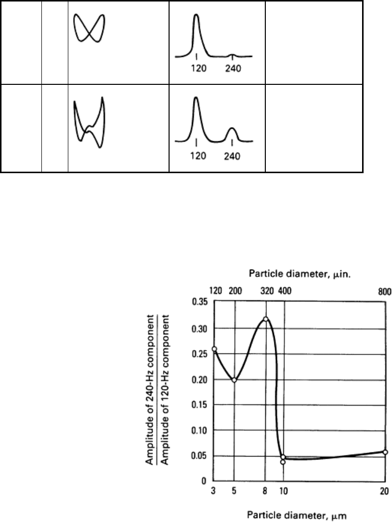
magabsorption detector. The magabsorption Lissajous figures for four samples of different particle sizes (5, 8, 10, and 20
μm) are given in Table 1. The fundamental frequency for each magabsorption signal is 120 Hz for a bias frequency of 60
Hz. The first harmonic of the signal is at 240 Hz, also as shown in the "Frequency spectrum" column in Table 1. The
vertical amplifier gain control was adjusted for each sample so that the magabsorption signal was of useful amplitude to
display the shape of the signal. The magabsorption signal amplitude is very low for the 5 and 8 m (200 and 320 in.)
samples and is very high for the 10 and 20 μm (400 and 800 in.) samples when the bias field is 0.024 T (240 G) peak-to-
peak. In the bottom row of Table 1, the peak-to-peak value of the bias field is reduced by 40 times to 6 × 10
-4
T (6 G)
peak-to-peak. This bias field reduction increased the ratio of the 240-Hz component relative to the 120-Hz component as
shown by a comparison between the data in the second row from the bottom with that from the bottom row. The second
row from the bottom uses a peak-to-peak bias field of 0.024 T (240 G), while the bottom row uses only 6 × 10
-4
T (6 G)
peak-to-peak. There is a distinctive change in the shape of the magabsorption signal from when the bias field is reduced
from 0.024 to 6 × 10
-4
T (240 to 6 G).
Table 1 Marginal-oscillator signals for iron carbonyl particles
The first four signals were obtained with a peak-to-peak bias field strength, H
B
, of 24 × 10
-3
T (240 G); the last signal, 0.6 × 10
-3
T (6
G).
Particle size
μm μin.
Oscilloscope Lissajous
patterns
Frequency
spectrum
Peak-to-peak
signal amplitude, mV
5 200
30
8 320
65
10 (HP)
400
2500
20 800
5000
20 800
38
There is also an increase in the ratio of the 240-Hz component to the 120-Hz component. The ratio of the amplitude of the
240-Hz component to the amplitude of the 120-Hz component is graphed in Fig. 22 for five particle sizes of carbonyl iron
powder in a bias field of 0.024 T (240 G) peak-to-peak. Figure 23 shows the root mean square (rms) magnitude of the
magabsorption signal plotted as a function of the peak-to-peak amplitude of the bias magnetic field.
Fig. 22 Ratio of the amplitude of the 240-Hz component to the amplitude of the 120-
Hz component for various
particle diameters of carbonyl iron with a magnetic field of 24 × 10
-3
T (240 G) peak-to-peak
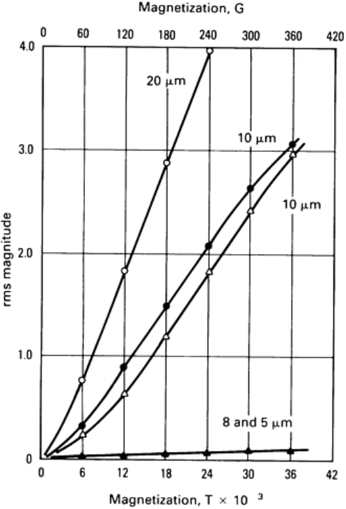
Fig. 23 Root mean square (rms) magnitude of the resistivity signal as a function of magnetization magnitude
During the experiments with powders, it was noticed that there was a difference in the magabsorption signal shape and
amplitude for iron oxide powders in different suspension media. The results with iron carbonyl particles indicate that the
more tightly the medium holds the particle, or the greater the viscosity of the medium, the larger the magabsorption signal
is. It was also noticed that when the iron carbonyl particles were allowed to settle, the signal decreased in amplitude by
ten times. When the particles were redistributed, the signal returned to its larger value.
Magabsorption Measurement of Stresses
As discussed in the section "B-H Characteristics" in this article and as illustrated in Fig. 4, stress can affect the orientation
of magnetic domains. When tension is applied to a saturated ferromagnetic material, with a positive magnetostriction
constant, some of the parallel-aligned domains have their direction reversed so that there are domains parallel and
antiparallel to the applied field. On the other hand, when tension is applied to a saturated ferromagnetic material such as
nickel with a negative magnetostriction constant, some of the parallel-aligned domains have their direction rotated 90° so
that there are domains perpendicular to the applied field. Therefore, the peak-to-peak magnitude and the shape of the
magabsorption signal depend on the direction of the magnetic bias field relative to the direction of the applied stress and
on whether the material has a positive or negative magnetostriction constant. The work on many types of materials has
shown that when the magnetic field bias, H
B
, is parallel to the direction of the applied stress, the following conditions
result:
•
For materials with a positive magnetostriction constant, increasing tension increases the signal
magnitude, while increasing compression decreases the amplitude (Fig. 24a)
•
For materials with a negative magnetostriction constant, increasing tension decreases the signal

magnitude, while increasing compression increases the amplitude (Fig. 24b)
Fig. 24 Amplitude (peak-to-
peak) of the magabsorption signals graphed as a function of stress (both tension
and compression) for materials with both positive and negative magnetostriction constants. The magnetic
bias
field is applied parallel to the stress direction.
These effects of stress on the peak-to-peak amplitude of the magabsorption signal are exactly the opposite for the
condition in which the direction of the magnetic bias field is perpendicular to the direction of the stress. The behavior of
the magabsorption signal peak-to-peak amplitude with the stress parallel to the direction of the magnetic bias field is
shown in Fig. 24. The maximum stress in each case is below the yield point of the material. The solid lines are for the
increasing stress in Fig. 24, while the broken lines are for the decreasing stress. In most materials, the magabsorption
amplitude for decreasing stress will not follow the curve for increasing stress, because there is a hysteresis.
Applied Stresses in Ferromagnetic Materials. Measurement of the magabsorption signal as a function of stress
has been performed on a variety of specimens. Measurements were made on iron and nickel wire and on a variety of bar
specimens.
Magabsorption Measurements on Wire. The block diagram of one system used to measure the magabsorption
signal in wires is shown in Fig. 19(a). The detection head consists of an RF coil and a Helmholtz pair of coils that supply
the bias magnetic field parallel to the axis of the wire. The RF magnetic field is also applied parallel to the axis of the
wire. The RF detection coil is fed through a coaxial cable to a marginal oscillator. The output of the marginal oscillator is
the magabsorption signal, and it is applied to the y-axis input of the oscilloscope. A voltage proportional to the current in
the bias field coils is fed to the horizontal input of the oscilloscope.
Another system for measuring the magabsorption signals from wires is a bridge circuit (Fig. 19b). The relative reversible
permeability curves for iron wire, unannealed nickel wire, and annealed nickel wire shown in Fig. 8 were taken with an ac
bridge. The magabsorption curves will also be similar to the curves of the relative reversible permeability.
Measurements of the magabsorption signal were made on iron and nickel wire as a function of stress. For the positive
magnetostriction constant material (iron), the peak-to-peak magnitude of the magabsorption signal from the material
increased with tension and decreased with compression when the bias field was parallel to the applied stress. The reverse
occurred when the material had a negative magnetostriction constant (nickel). When iron and nickel have residual stress
and additional stress is applied, the peak-to-peak magnitude of the magabsorption signal may be less than that for no
residual stress.
Magabsorption Measurements on Bar Specimens. Many measurements with magabsorption detector heads
(such as the one shown in Fig. 20) have been made on bar specimens with the bias field both perpendicular (Fig. 25a) and
parallel (Fig. 25b) to the stress direction.
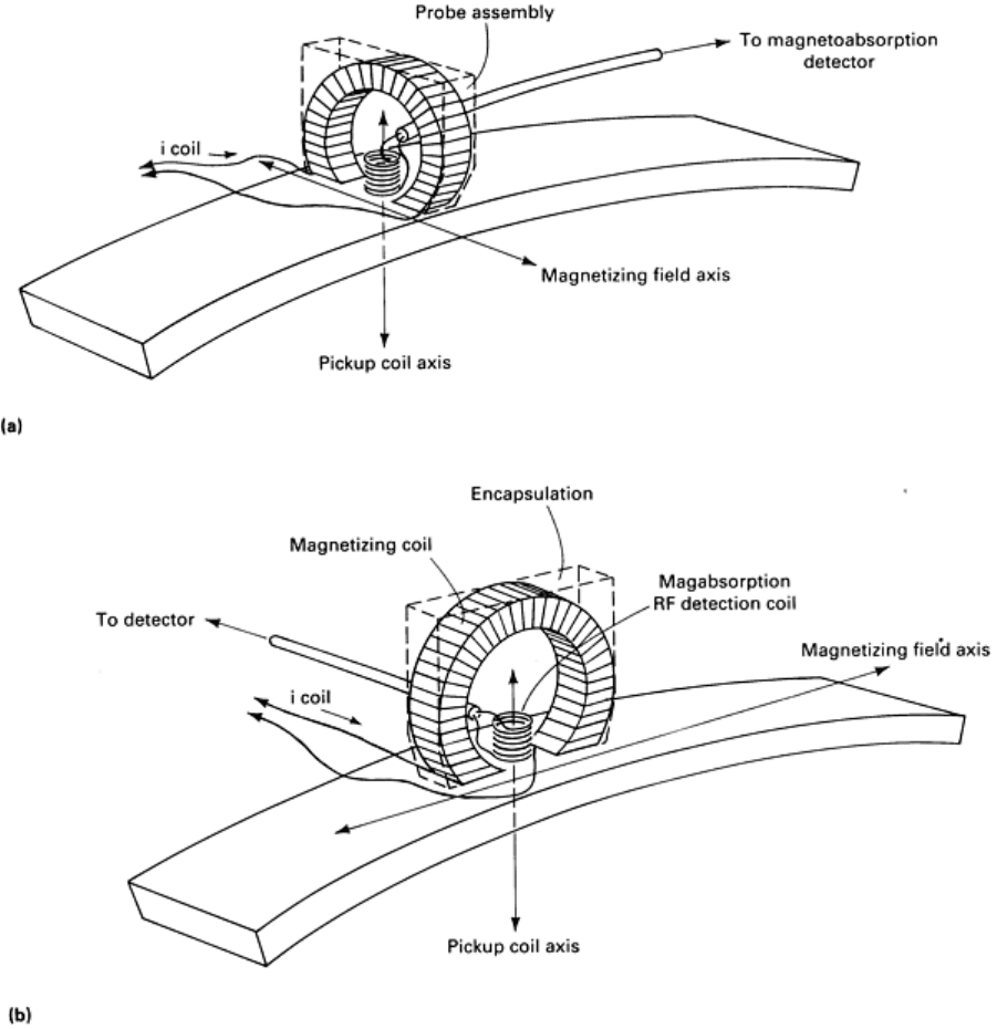
Fig. 25
Probe specimen geometry for parallel and perpendicular magabsorption measurements on a bent steel
bar. (a) Probe in transverse or perpendicular position. (b) Probe in axial or parallel position
A number of measurements were made on type 1018 steel bars (Ref 7). Graphs were constructed of the peak-to-peak
magabsorption signal amplitude as a function of the stress, both tension and compression, applied as a bending moment.
Additional similar measurements were made on bars of 410 and 4340 steel.
Another series of measurements was obtained from a 5046 steel crankshaft throw (Ref 11). The measurement procedure
was very similar to that described above except that the detection heads (Fig. 20) were made much smaller and were
ground curved to fit the curves of the crankshaft throw.
Stresses in Nonferromagnetic Materials. It has also been shown that when a nonferromagnetic material is coated
with a thin layer of ferromagnetic material, there exists a possibility of measuring stress at the surface of the
nonferromagnetic material from the magabsorption signals of the ferromagnetic coating (Ref 6). This requires good
adherence of the coating in order to reduce the distortion of strain transmitted from the base material to the coating. The
strain transmitted to the coating may also exhibit additional distortion if the testpiece is not plane-stressed.
If the strains are assumed equal in the plating and in the base material, the stresses are related by:
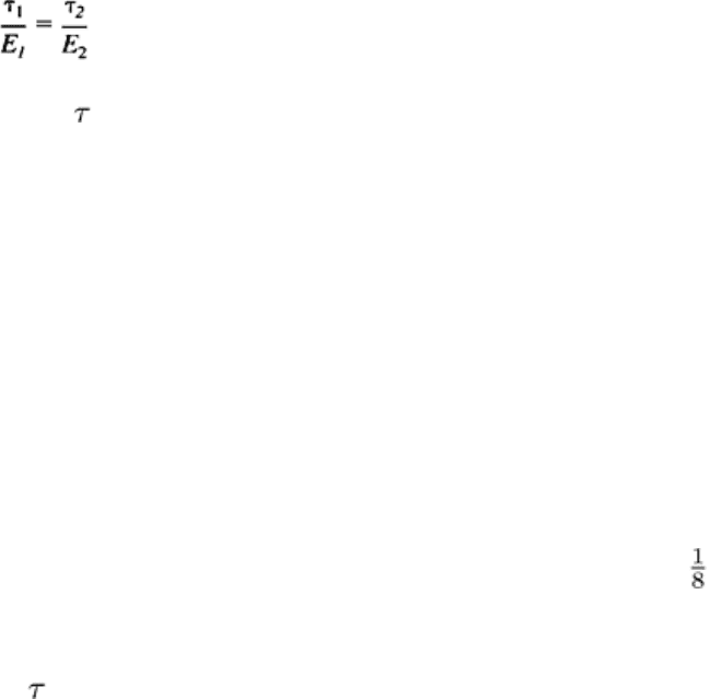
(Eq 18)
within the proportional limit where
i
is the stress and E
i
(where i = 1,2) is the modulus of elasticity for the two materials.
In Eq 18, i = 1 refers to the substrate and i = 2 refers to the ferromagnetic coating. Thus, if the ratio of the moduli is
known and T
2
is the stress in the ferromagnetic coating as measured by the magabsorption technique, then the stress at the
surface of the substrate can be determined.
For the experimental work reported in Ref 6, aluminum welding rods were plated with nickel. As mentioned previously, it
is important that the coating adheres well to the base material. It has been reported in the literature "that the bond strength
of a nickel plating is of the order of the tensile strength of the base material when a phosphoric acid anodizing
pretreatment process is employed." Studies of this anodizing process by the Southwest Research Institute have shown no
blistering or separation in nickel-plated aluminum samples when subjected to a 180° bend of one thickness radius.
Because the nickel plating adheres this well, the strain in the base metal was assumed to be the same as that in the plated
material.
A loading device was used to apply the stress (tension) to the nickel-plated aluminum welding rods. Both tension and
strain were measured. The marginal oscillator type of magabsorption detector was used to deliver the in-phase
magabsorption signal. For each sample, the data were reduced so that strain and peak-to-peak magabsorption magnitude
could be plotted as a function of stress. The graph of strain versus stress for a nickel-plated 3 mm ( in.) diam aluminum
rod and a graph of the peak-to-peak amplitude of the magabsorption signals from the nickel plating as a function of stress
are given in Fig. 26. For this test, the plated aluminum sample is not annealed after plating. The dashed line in Fig. 26 is
the empirical (curve-fitted) relationship between the magabsorption amplitude, A, and the applied stress (in psi) is given
by the equation A = 0.96 exp (-
1
/1360).
