ASM Metals HandBook Vol. 17 - Nondestructive Evaluation and Quality Control
Подождите немного. Документ загружается.


Effect of External Conductors on Sensor Sensitivity. A different type of limitation is that the sensor is also
affected by conducting material placed in contact with the tube exterior. The most common examples of this situation are
tube supports and tube sheets. This effect is produced because the sensor is sensitive to signals coming from the pipe
exterior. For tube supports, a characteristic pattern occurs that varies when a flaw is present. While allowing flaw
detection, this information is probably recorded at a reduced sensitivity. Geometries such as finned tubing weaken the
RFEC signal and add additional signal variation to such an extent that the technique is not practical under these
conditions.
Difficulty in Distinguishing Flaws. Another limitation is that measuring exciter/ sensor phase lag and correlating
remaining wall thickness leads to nondiscrimination of outside diameter flaws from inside diameter flaws. Signals
indicating similar outside and inside diameter defects are nearly identical. However, conventional eddy current probes can
be used to confirm inside-diameter defects.
Reference cited in this section
1.
T.R. Schmidt, The Remote-Field Eddy Current Inspection Technique, Mater. Eval., Vol 42, Feb 1984
Remote-Field Eddy Current Inspection
J.L. Fisher, Southwest Research Institute
Current RFEC Research
No-Flaw Models. Most published research regarding RFEC inspection has been concerned with interpreting and
modeling the remote-field effect without flaws in order to explain the basic phenomenon and to demonstrate flaw
detection results. The no-flaw case has been successfully modeled by several researchers, including Fisher et al. (Ref 2),
Lord (Ref 3), Atherton and Sullivan (Ref 4), and Palanissimy (Ref 5), using both analytical and finite-element techniques.
This work has shown that in the remote-field region the energy detected by the sensor comes from the pipe exterior and
not directly from the exciter. This effect is seen in several different ways. For example, in the Poynting vector plot shown
in Fig. 5, the energy flow is away from the pipe axis in the near-field region, but in the remote-field region a large area of
flow has energy moving from the pipe wall toward the axis. In the magnetic field-line plot shown in Fig. 6, the magnetic
field in the remote-field region is greater near the tube outside diameter than near the inside diameter. This condition is
just the opposite from what one would expect and from what exists in the near-field region. The energy diffusion is from
the region of high magnetic field concentration to regions of lower field strength.
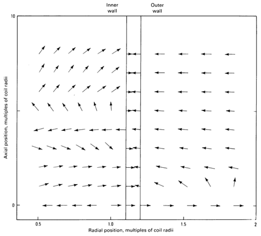
Fig. 5 Poyntin
g vector field showing the direction of energy flow at any point in space. This more directly
demonstrates that the direction of energy flow in the remote-
field region is from the exterior to the interior of
the pipe.
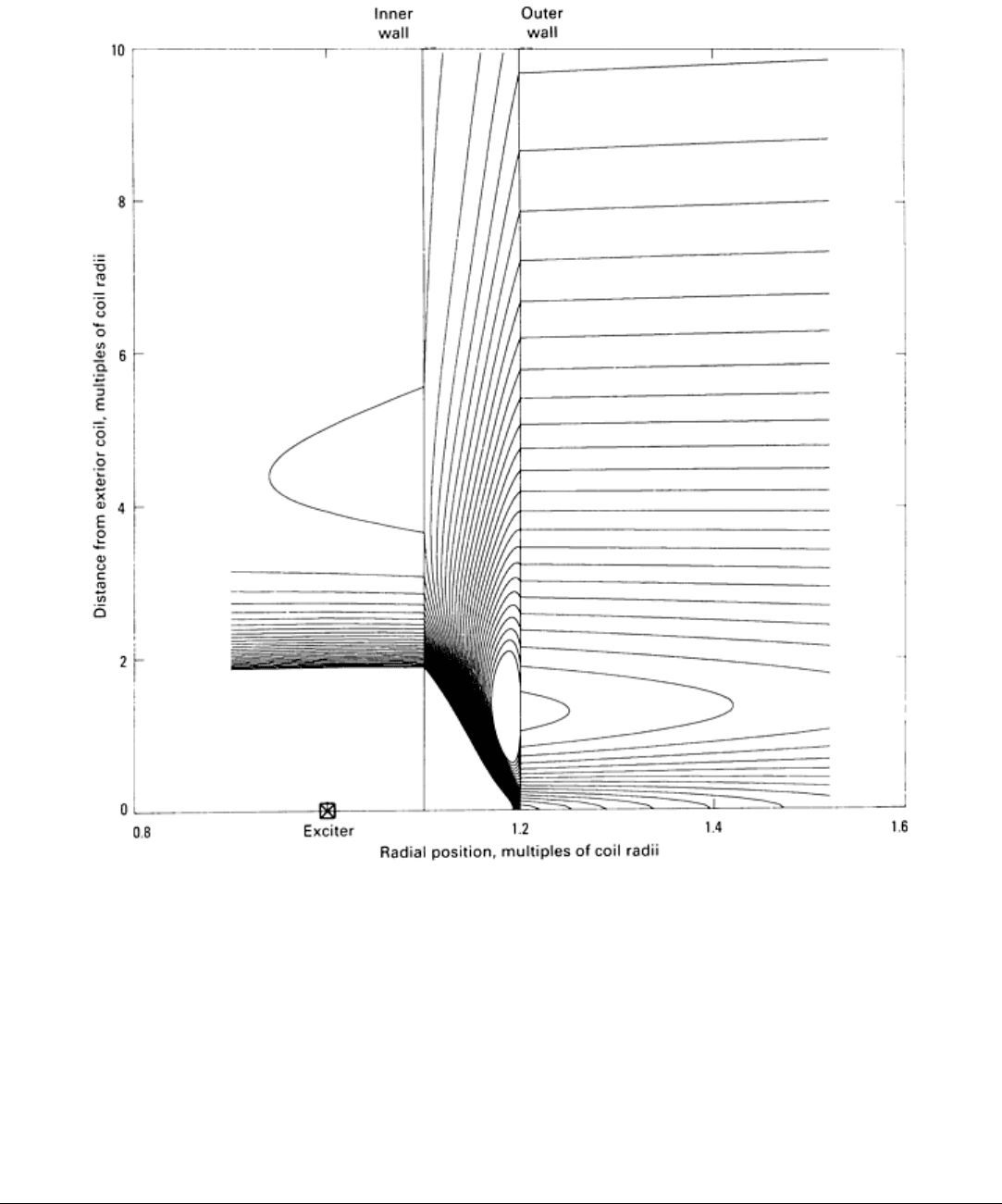
Fig. 6
Magnetic field lines generated by the exciter coil and currents in the pipe wall. The greater line density in
the pipe closer to the outside wall in the remote-
field region confirms the observation that field energy diffuses
into the pipe interior from the exterior. A significant number of the field lines have been suppressed.
Flaw models with the RFEC geometry have been generated more rarely. The problem is that realistic flaw models
require the use of three-dimensional modeling, something that is difficult to achieve with eddy current testing. One model
by Fisher et al. (Ref 2) used a boundary-element calculation in conjunction with the two-dimensional, unperturbed-field
calculation to predict the response to pitting. The response to outside-diameter and inside-diameter slots has been
modeled with two-dimensional finite-element programs (Ref 3).
References cited in this section
2.
J.L. Fisher, S.T. Cain, and R.E. Beissner, Remote Field Eddy Current Model, in
Proceedings of the 16th
Symposium on Nondestructive Evaluation (San Antonio, TX), Nondestructive
Testing Information Analysis
Center, 1987
3.
W. Lord, Y.S. Sun, and S.S. Udpa, Physics of the Remote Field Eddy Current Effect, in
Reviews of Progress

in Quantitative NDE, Plenum Press, 1987
4.
D.L. Atherton and S. Sullivan, The Remote-Field Through-Wall
Electromagnetic Technique for Pressure
Tubes, Mater. Eval., Vol 44, Dec 1986
5.
S. Palanissimy, in Reviews of Progress in Quantitative NDE, Plenum Press, 1987
Remote-Field Eddy Current Inspection
J.L. Fisher, Southwest Research Institute
Techniques Used to Increase Flaw Detection Sensitivity
Two general areas--sensor configuration and signal processing--have been identified for improvements in the use of
RFEC inspection that would allow it to achieve greater effective flaw sensitivity.
Sensor Configuration. For the detection of localized flaws, such as corrosion pits, the results of the unperturbed and
the flaw-response models suggest that a receiver coil oriented to detect magnetic flux in a direction other than axial might
provide increased flaw sensitivity. This suggestion was motivated by the fact that the field lines in the remote-field region
are approximately parallel to the pipe wall, as shown in Fig. 6. Thus, a sensor designed to pick up axial magnetic flux, B
z
,
would always respond to the unperturbed (no-flaw) field; a flaw response would be a perturbation to this primary field. If
the sensor were oriented to receive radial flux, B
r
, then the unperturbed flux would be reduced and the flaw signal
correspondingly enhanced. This approach has been successful; a comparison of a B
z
sensor and a B
r
sensor used to detect
simulated corrosion pits showed that the B
r
probe is much more sensitive. A B
r
sensor would also minimize the
transmitter coil signal from a flaw, which is always present when a B
z
sensor is used, thus eliminating the double signals
from a single source. This configuration appears to be very useful for the detection of localized flaws, but does not appear
to have an advantage for the measurement of wall thickness using the unperturbed field.
Signal Processing. The second area of possible improvement in RFEC testing is the use of improved signal-processing
techniques. Because it was observed that the exciter/sensor phase delay was directly proportional to wall thickness in
ferromagnetic tubes, measurement of sensor phase has been the dominant method of signal analysis (Ref 1). However, it
is possible to display both the magnitude and phase of the sensor voltage or, correspondingly, the complex components of
the sensor voltage. This latter representation (impedance plane) is identical to that used in modern eddy current testing
instrumentation for probes operated in a driver/pickup mode. Figures 7 and 8 show the results of using this type of
display. Figure 7 shows the data from a scan through a carbon steel tube with simulated outside surface pits of 30, 50, and
70% of nominal wall thickness. A B
r
probe was used for the experiment. Figure 8 shows the horizontal and vertical
channels after the scan data were rotated by 100°. Much of the noise was eliminated in this step.
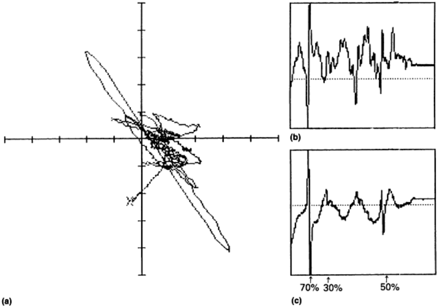
Fig. 7 Signal processing of impedance-plane sensor voltage in RFEC testing. (a) RFEC scan with a B
r
probe
through a carbon steel tube with outside surface pits that were 30, 50, and 70% of wall thickness depth. Each
graduation in x and y direction is 10 V. (b) Horizontal channel at 0° rotation. (c)
Vertical channel at 0° rotation.
Signal amplitudes in both (b) and (c) are in arbitrary units. Only the 70% flaw stands out clearly.
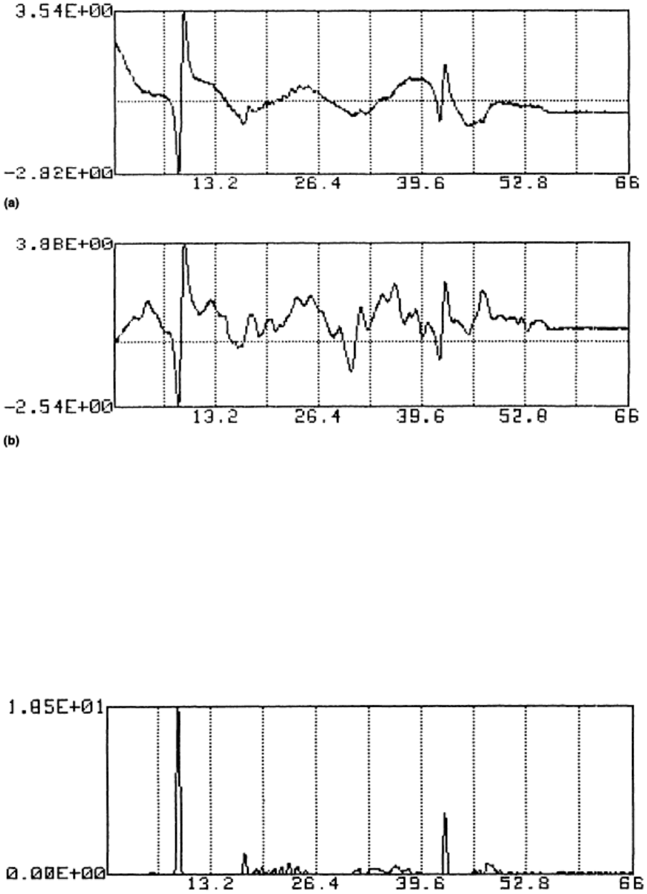
Fig. 8 Horizontal (a) and vertical (b) data of Fig. 7 after 100° rotation. Signal amplitudes are in arbitrary units.
An additional possible signal-processing step is to use a correlation technique to perform pattern matching. Because the B
r
sensor has a characteristic double-sided response to a flaw, flaws can be distinguished from material variations or
undesired probe motion by making a test sensitive to this shape. This effect is achieved by convolving the probe signals
with a predetermined sample signal that is representative of flaws. The results of one test using this pattern-matching
technique are shown in Fig. 9. It is seen that even though the three flaws have a range of depths and diameters, the
correlation algorithm using a single sample flaw greatly improves the signal-to-noise ratio.
Fig. 9 Data from Fig. 8
processed with the correlation technique. All three flows are now well defined. Signal
amplitude is in arbitrary units.
Other signal-processing techniques that show promise include the use of high-order derivatives of the sensor signal for
edge detection and bandpass and median filtering to remove gradual variations and high-frequency noise (Ref 6).

References cited in this section
1.
T.R. Schmidt, The Remote-Field Eddy Current Inspection Technique, Mater. Eval., Vol 42, Feb 1984
6.
R.J. Kilgore and S. Ramchandran, NDT Solution: Remote-
Field Eddy Current Testing of Small Diameter
Carbon Steel Tubes, Mater. Eval., Vol 47, Jan 1989
Remote-Field Eddy Current Inspection
J.L. Fisher, Southwest Research Institute
Applications
*
Remote-field eddy current testing should be considered for use in a wider range of examinations because its fundamental
physical characteristics and limitations are now well understood. The following two examples demonstrate how
improvements in RFEC probe design and signal processing have been successfully used to optimize the operation of key
components in nuclear and fossil fuel power generation.
Example 1: Gap Measurement Between Two Concentric Tubes in a Nuclear Fuel
Channel Using a Remote-Field Eddy Current Probe.
The Canadian Deuterium Uranium reactor consists of 6 m (20 ft) long horizontal pressure tubes containing the nuclear
fuel bundles. Concentric with these tubes are calandria tubes with an annular gap between them. Axially positioned garter
spring spacers separate the calandria and pressure tubes. Because of unequal creep rates, the gap will decrease with time.
Recently, it was found that some garter springs were out of position, allowing pressure tubes to make contact with the
calandria tubes.
Because of this problem, a project was initiated to develop a tool to move the garter springs back to their design location
for operating reactors. Successful use of this tool would require measurement of the gap during the garter spring
unpinching operation. The same probe could also be used to measure the minimum gap along the pressure tube length.
Because the gap is gas filled, an ultrasonic testing technique would not have been applicable.
At low test frequencies, an eddy current probe couples to both the pressure tube and the calandria tube (Fig. 10a). The gap
component of the signal is obtained by subtracting the pressure tube signal from the total signal. Because the probe is near
or in contact with the pressure tube and nominally 13 mm ( in.) away from the calandria tube, most of the signal comes
from the pressure tube. In addition, the calandria tube is much thinner and of higher electrical resistivity than the pressure
tube, further decreasing the eddy current coupling. To overcome the problem of low sensitivity with large distances (>10
mm, or 0.4 in.), a remote-field eddy current probe was used. Errors in gap measurement can result from variations in:
• Lift-off
• Pressure tube electrical resistivity
• Ambient temperature
• Pressure tube wall thickness
Multifrequency eddy current methods exist that significantly reduce the errors from the first three of the above-mentioned
variations, but not for wall thickness variations. This is because of minimal coupling to the calandria tube and because the
signal from the change in gap is similar (in phase) to the signal from a change in wall thickness (at all test frequencies).
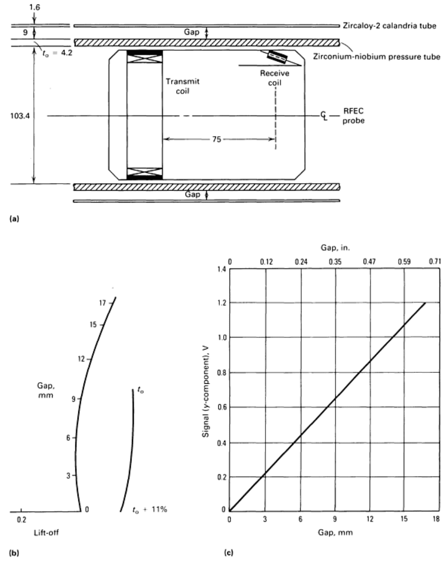
Fig. 10
Gap measurement between two concentric tubes in a nuclear fuel channel with an RFEC probe. (a)
Cross-sectional view of probe and test sample. Dimensions given in millimet
ers. (b) Plot of eddy current signals
illustrating effect of gap, wall thickness, and lift-off. Dimensions given in millimeters. (c) Plot of y-
component of
signal versus gap at a frequency of 3 kHz. Source: V.S. Cecco, Atomic Energy of Canada Limited
The inducing magnetic field from an eddy current probe must pass through the pressure tube wall to sense the calandria
tube. The upper test frequency is limited by the high attenuation through the pressure tube wall and the lower test
frequency by the low coupling to the pressure tube and calandria tube. In addition, at low test frequency, there is poor
signal discrimination because of variations in lift-off, electrical resistivity, wall thickness, and gap. In practice, 90° phase
separation between lift-off and gap signals gives optimum signal-to-noise and signal discrimination. For this application,
the optimum test frequency was found to be between 3 and 4 kHz.
Typical eddy current signals from a change in pressure tube to calandria tube gap, lift-off, and wall thickness are shown in
Fig. 10(b). The output signal for the complete range in expected gap is linear, as shown in Fig. 10(c). To eliminate errors
introduced from wall thickness variations, the probe body includes an ultrasonic normal beam transducer located between
the eddy current transmit and receive coils. This combined eddy current and ultrasonic testing probe assembly with a
linear output provides an accuracy of ± 1 mm (±0.04 in.) over the complete gap range of 0 to 18 mm (0 to 0.7 in.).
Example 2: RFEC Inspection of Carbon Steel Mud Drum Tubing in Fossil Fuel
Boilers.
Examination of the carbon steel tubing used in many power boiler steam generators is necessary to ensure their safe,
continuous operation. These tubes have a history of failure due to attack from acids formed from wet coal ash, as well as
erosion from gas flow at high temperatures. Failure of these tubes from thinning or severe pitting often requires shutdown
of the system and results in damage to adjacent tubes or to the entire boiler. The mud drum region of the steam generator
is one such area. Here the water travels up to the superheater section, and the flame from the burners is directed right at
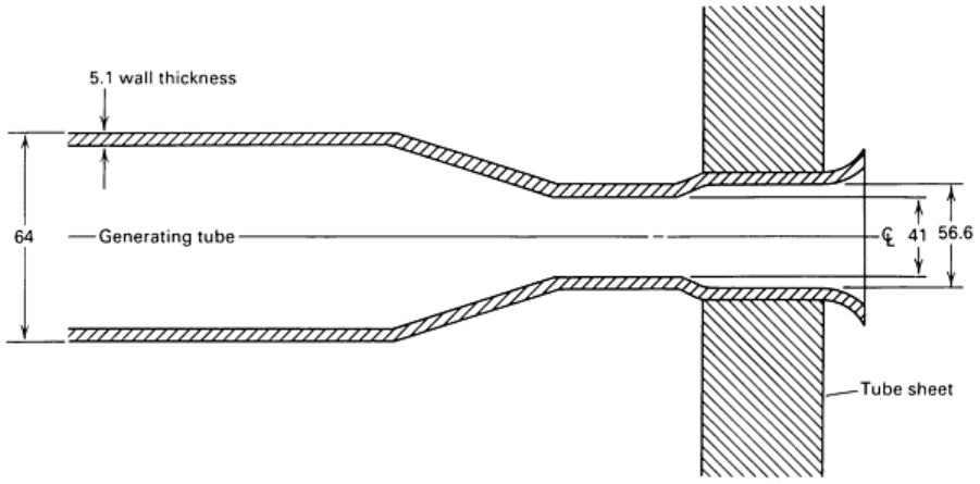
the tubes just leaving the mud drum. The tubes in this region are tapered and rolled into the mud drum (Fig. 11), then they
curve sharply upward into the superheater section.
Fig. 11
Geometry and dimensions of 64 mm (2.5 in.) OD carbon steel generating tubes at a mud drum. The
tube is rolled into a tube sheet to provide a seal as shown. Dimensions given in millimeters
The tubes are constructed of carbon steel typically 64 mm (2.5 in.) in outside diameter, and 5.1 mm (0.2 in.) in wall
thickness. A conventional eddy current test would be ineffective, because the eddy currents could not penetrate the tube
wall and still influence coil impedance in a predictable manner. Ultrasonic testing could be done, but would be slow if
100% wall coverage were required. The complex geometry of the tube, the material, and the 41 mm (1.6 in.) access
opening necessitated that a different technique be applied to the problem.
Because the RFEC technique behaves as if it were a double through transmission effect, changes in the fill factor are not
as significant as they would be in a conventional eddy current examination. This allowed the transmitter and receiver to
be designed to enter through the 41 mm (1.6 in.) opening. Nylon brushes recentered the RFEC probe in the 56.6 mm (2.23
in.) inside diameter of the tube. To maintain flexibility of the assembly and still be able to position the inspection head,
universal joints were used between elements.
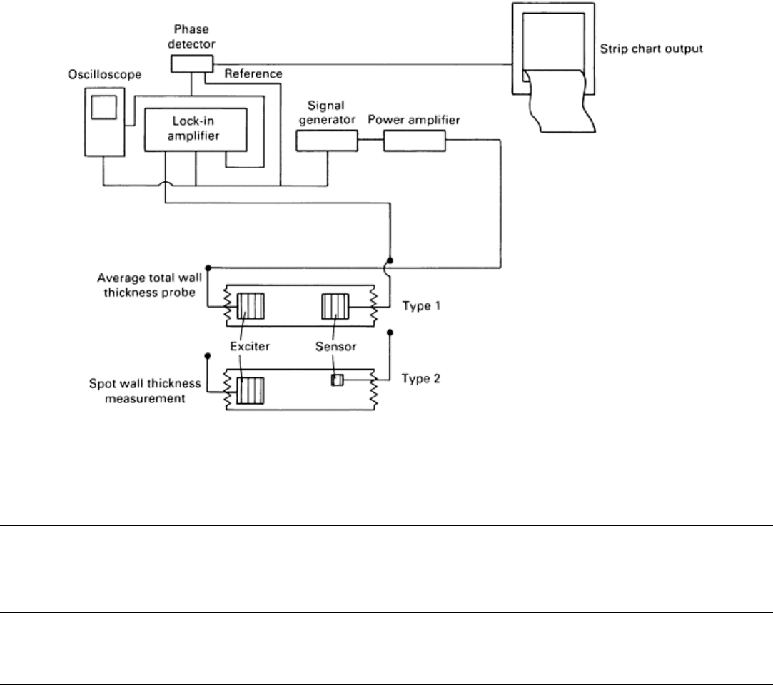
The instrumentation used in this application was a combination of laboratory standard and custom-designed components
(Fig. 12). The Type 1 probe was first used to locate any suspect areas, then the Type 2 probe was used to differentiate
between general and local thinning of the tube wall. This technique was applied to the examination of a power boiler, and
the results were compared to outside diameter ultrasonic readings where possible. Agreement was within 10%.
Fig. 12 Breadboard instrumentation necessary to excite and receive the 45-
Hz signal. Analysis was based on
the phase difference between the reference and received signals.
Note cited in this section
* Example 1 was prepared by V.S. Cecco, Atomic Energy of Canada Limited.
Remote-Field Eddy Current Inspection
J.L. Fisher, Southwest Research Institute
References
1. T.R. Schmidt, The Remote-Field Eddy Current Inspection Technique, Mater. Eval., Vol 42, Feb 1984
2. J.L. Fisher, S.T. Cain, and R.E. Beissner, Remote Field Eddy Current Model, in Pr
oceedings of the 16th
Symposium on Nondestructive Evaluation
(San Antonio, TX), Nondestructive Testing Information Analysis
Center, 1987
3. W. Lord, Y.S. Sun, and S.S. Udpa, Physics of the Remote Field Eddy Current Effect, in
Reviews of
Progress in Quantitative NDE, Plenum Press, 1987
4. D.L. Atherton and S. Sullivan, The Remote-Field Through-
Wall Electromagnetic Technique for Pressure
Tubes, Mater. Eval., Vol 44, Dec 1986
5. S. Palanissimy, in Reviews of Progress in Quantitative NDE, Plenum Press, 1987
6. R.J. Kilgore and S. Ramchandran, NDT Solution: Remote-
Field Eddy Current Testing of Small Diameter
Carbon Steel Tubes, Mater. Eval., Vol 47, Jan 1989
