ASM Metals HandBook Vol. 17 - Nondestructive Evaluation and Quality Control
Подождите немного. Документ загружается.

• Radiography permits internal inspection of a component
• Radiography supplies a permanent visual record
• Radiography is generally sensitive to discontinuities commonly present in welds
The use of radiography is generally restricted to the inspection of welds for the following reasons:
• The cost of performing radiographic inspections is high when compared to other available methods
• Radiographic inspection of large areas is relatively slow
• Radiography is insensitive to laminar-type discontinuities
Radiography can be used, if the proper equipment is available, to inspect welds in steel pressure vessels with walls up to
400 mm (16 in.) thick. The only conditions that could limit the use of radiography for the inspection of welds in pressure
vessels are, first, a lack of accessibility to both sides of the weld for placement of the film and the radiation source and,
second, a high degree of variability in shape and thickness in the area being inspected. Both single-wall and double-wall
techniques are commonly employed for the radiographic inspection of pipe. Detailed discussions of these techniques are
available in the article "Radiographic Inspection" in this Volume. The following examples describe standard radiographic
techniques used to inspect common welded seams in pressure vessels.
Example 1: Radiographic Inspection of Longitudinal, Girth, and Nozzle Welds in
a Carbon Steel Pressure Vessel.
The pressure vessel shown in Fig. 7 was used in a commercial nuclear application and was inspected in accordance with
section III of the ASME Boiler and Pressure Vessel Code. The material was 65 mm (2 in.) thick carbon steel. The weld
joints were single-V grooves and were welded using the submerged arc process for both the longitudinal and girth seams.
Shielded metal arc welding was used to join the nozzle to the vessel.
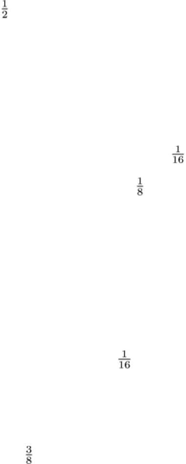
Fig. 7 Nuclear pressure vessel, of 65 mm (2 in.) thick carbon steel,
in which longitudinal, girth, and nozzle
welds were radiographically inspected using 50-Ci cobalt-
60 as the radiation source, Eastman Kodak type AA
radiographic film, and the inspection setups shown. Dimensions given in inches
For radiographic inspection, cobalt-60 was selected as the radiation inspection because of the thickness of the material,
and Eastman Kodak type AA film was selected for its relative speed to give the shortest exposure time. The combination
of Co-60 and type AA film can sometimes result in marginal sensitivity that occasionally requires the reshooting of a
specific region.
Each longitudinal seam was radiographically inspected with eight shots spaced 350 mm (14 in.) apart using a 180 × 430
mm (7 × 17 in.) film. The penetrameters were steel ASTM No. 45 with a 1.5 mm ( in.) thick shim. The Co-60
radiation source was placed 690 mm (27 in.) from the film. The cassette was loaded with a 0.25 mm (0.010 in.) thick lead
screen, two pieces of film, a 0.25 mm (0.010 in.) thick lead screen, and a 3 mm ( in.) thick lead back shield. Section A-
A in Fig. 7 shows the setup for radiographic inspection of the longitudinal seam.
The girth weld was inspected using the panoramic technique, in which the Co-60, 50-Ci radiation source was placed at the
center of the vessel and 28 film cassettes were placed around the outer surface (section B-B, Fig. 7). The technique
involves only one exposure of 25 min to radiograph the entire seam, but its success depends on the placement of the
radiation source exactly in the center of the vessel. The disadvantages of this technique include a lengthy setup time, a
fairly complicated setup, and additional film costs if an error is made.
An alternative technique is to place the radiation source outside the vessel and inspect the seam with 28 separate
exposures. This method would result in higher-quality radiographs, but a much longer total exposure time would be
required.
Three equally spaced steel ASTM No. 45 penetrameters with 1.5 mm ( in.) thick shims were used for the 28
radiographs. The film size and the types and thicknesses of screens and filters were the same as those used for the
longitudinal seam welds.
The nozzle seam weld was radiographed using eight 13-min exposures. As shown in section C-C in Fig. 7, the radiation
source was placed outside the vessel and was offset at an angle of 7 to 10° away from the nozzle. The source-to-film
distance was 900 mm (36 in.). The variation in weld thickness at the nozzle required that two penetrameters be used. One
was flush to the sidewall, and the other had a 9 mm ( in.) thick shim, which compensated for the difference in weld
thickness. This two-penetrameter setup qualified the sensitivity of the radiograph because of the differential thickness of
the weld being inspected. A sensitivity of 2-2T and a density of 2.0 were specified for the radiographs of all three types of
welds.
Example 2: Radiographic Inspection for Creep Fissures in Reformer-Furnace
Tubes
(Ref 14). About 1 year after start-up, two steam-methane reformer furnaces were subjected to short-time heat excursions
because of a power outage, which resulted in creep bulging in the Incoloy 800 outlet pigtails, requiring complete
replacement. It was thought that during this heat excursion some of the reformer tubes experienced slight bulging, about
1%, by plastic deformation. However, this type of bulging does not necessarily shorten the life of a tube in terms of creep.
Each furnace had three cells, consisting of 112 vertical tubes per cell, each filled with a nickel catalyst. The tubes were
centrifugally cast from ASTM A297, grade HK-40 (Fe-25Cr-20Ni-0.40C), heat-resistant alloy. The tubes had an outside
diameter of 150 mm (5.85 in.) and a minimum wall thickness as-cast of 20 mm (0.802 in.), and they were more than 13.7
m (45 ft) in length. The design limits for the tubes were 2200 kPa (320 psi), with a surface temperature of 958 °C (1757
°F). Operating limits were 2140 kPa (310 psi) at a surface temperature of 943 °C (1730 °F). The furnace cell is illustrated
in Fig. 8(a).
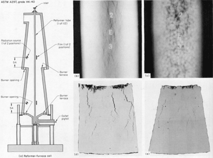
Fig. 8 Reformer-furnace cell from which cast tubes of ASTM A 297, HK-40, heat-
resistant alloy were
radiographically inspected for the detection of creep fissuring. (a) Schematic of furnace cell showing positions of
radiographic sources and films. Dimensions given in inches
. (b) Radiograph of a section removed from a failed
tube that contained no catalyst showing fissures near the ruptured area. (c) Same section as (b) but containing
a catalyst. Fissures are visible but less apparent. (d) Macrograph showing fissures in a tub
e that were detected
by radiography. 6×. (e) Macrograph showing fine fissuring that was not indicated by radiography. 6×
The first tube failure occurred after 33,000 h of operation. The unit was shut down, and the failed tube was removed for
metallurgical inspection. The results indicated that the tube failed from creep rupture (stress rupture). The tube failure
instigated a project for detecting midwall creep fissuring. Radiography had been reported to be limited to detecting only
severe third-stage creep and not the early stages.
Laboratory Radiography. Preliminary studies were made to determine type of radiation source and strength, radiation
source-to-film distance, exposure time, and effect of catalyst in tube. Figure 8(b) shows a laboratory radiograph of a
section removed from the failed tube without catalyst. Fissures were clearly visible near the ruptured area and diminished
to nondetectable fissures at a point 400 mm (16 in.) below the rupture. The same tube section radiographed under similar
conditions but with catalyst in the tube is shown in Fig. 8(c). Fissures are visible, but it is apparent that the catalyst
reduced the sensitivity by masking the smaller fissures.
Liquid penetrant inspection and macroexamination of the specimen tube revealed the gross fissuring that was easily
detectable and those fissures that were undetectable by radiography. The largest fissures undetectable by radiography
were approximately 3 mm (0.125 in.) long and 0.13 mm (0.005 in.) wide. (Fissures have been detected that were between
5 and 10 mm, or 0.200 and 0.400 in., long.)
Based on the radiography and macroexamination results, it was decided that future tube replacements would be inspected
by radiography, preferably with the catalyst removed. If the fissure were large enough to show on a radiograph, either
with or without the catalyst, the tube could be expected to fail within 1 year.
In-Service Radiographic Inspection. During shutdown of one furnace, the first full test of the radiographic
inspection method was made. All the tubes were measured for evidence of outside diameter growth, and the suspect areas

were strapped to identify the hottest zones. Growth to failure in HK-40 material having a rough exterior surface is
difficult to measure, because total creep of only about 1% has occurred by the time of failure. Gaging did not show much,
but strapping on some tubes clearly identified bulging in the hottest areas about 1.4 m (54 in.) above the burner terrace.
This was used as the basis for radiographing all other tubes.
The catalyst was removed from the tubes in preparation for radiography. Two IR-192 radiation sources having a strength
of 3300 GBq (90 Ci) and one 3700 GBq (100 Ci) source were used, mounted in jigs at distances of 750 and 900 mm (30
and 36 in.), respectively, from the film. A tungsten collimator was also used to limit the emission to a single tube and
permit the technicians to remain in the firebox during exposure. Exposure time was 7 to 10 min per shot, and
approximately 700 shots were taken.
Shortly after the first furnace was back on stream, the second furnace was shut down and the tubes radiographed. Using
the same techniques but with a 3900 GBq (105 Ci) source, time to radiograph the second furnace was reduced about 25%.
Twenty-four tubes in the first furnace and 53 in the second furnace showed significant fissuring. One of these fissured
tubes was left in the first furnace and 15 in the second; when these tubes eventually failed, they would provide an
indication of remaining life after a known radiographic examination.
One of the tubes that had been removed from the furnace was sectioned at two places--through a radiographic indication
of a fissure and through an area containing no indications. Macrographs of these sections are shown in Fig. 8(d) and 8(e).
Figure 8(d) shows fissuring that was detected by radiography. Fine fissuring that was not seen on the radiograph is shown
in Fig. 8(e).
Conclusion. Radiography was a practical, economical method of detecting the creep fissuring, and it provided advance
information for purchase of replacement tubes. However, because radiography was limited to detecting fissures caused by
third-stage creep in tubes from which the nickel catalyst had been removed and because of the cost of removing the
catalyst, ultrasonic techniques were developed for inspecting the tubes. These techniques are described in Example 4 in
this article.
Reference cited in this section
14.
R.R. Dalton, Radiographic Inspection of Cast HK-40 Tubes for Creep Fissures, Mater. Eval.,
Vol 30 (No.
12), Dec 1972, p 249-253
Nondestructive Inspection of Boilers and Pressure Vessels
Ultrasonic Inspection of Pressure Vessels
Volumetric inspections are used to inspect the volume of material bounded by the surfaces of components and of piping.
Theoretically, any source of energy that penetrates the volume of a material can be used. In practice, however, only x-
rays, -rays, and ultrasonic waves are used. In nuclear vessels, which are housed in a containment building, radiographic
inspection methods for in-service inspection currently have limited use because of the need for access to both surfaces
and because of the high -ray background in most areas of the containment building. When radiography is used, other
inspection methods such as acoustic emission can also be used for additional monitoring. However, a large number of
inspections are performed using various ultrasonic techniques.
As described in the article "Ultrasonic Inspection" in this Volume, ultrasonic waves are generated by piezoelectric
transducers that convert high-frequency electrical signals into mechanical vibrations. These mechanical vibrations form a
wave front, which is coupled to the vessel being inspected through the use of a suitable medium. Several wave modes can
be used for inspection, depending on the orientation and location of the discontinuities that exist. Longitudinal, shear, and
surface waves are used separately in different techniques to reveal discontinuities that are respectively parallel to, at an
angle to, and on or near the surface from which the inspection is performed. These inspections are made with longitudinal
wave transducers, pulse-echo, through transmission, pitch-catch, or delta techniques. Most of the inspections are
performed using pulse-echo straight longitudinal wave beams and angled shear wave beams from a single transducer.
Manual ultrasonic inspection is performed with single-transducer pulse-echo techniques. The ultrasonic wave is
coupled to the component being inspected through a couplant (usually a glycerin or light oil) that transports the
ultrasound between the face of the transducer and the surface of the component. In longitudinal wave straight-beam
inspection, ultrasonic waves enter normal to the surface and will detect discontinuities perpendicular to the direction of
wave propagation. In angle-beam inspection, the longitudinal wave is coupled through a plastic wedge at an angle to the
surface. The wave is again coupled to the component (still a longitudinal wave) and undergoes a mode conversion to a
shear wave. The angle of the resulting shear wave is dependent on the ratio of the combination of ultrasonic velocities in
the plastic wedge and the metal component with the angle of the incident longitudinal wave in the plastic wedge. Shear
wave angles from 40 to 75° are used for inspection. Indications are recorded and plotted from reference locations on the
weld metal.
Automated Ultrasonic Inspection. For accurate inspections, immersion ultrasonic inspection provides the highest
level of inspection speed, accuracy, and repeatability. The coupling of ultrasonic waves is done with much less variability
in couplant thickness and transducer pressure than occurs in manual techniques. The immersion method permits
automated scanning and digital recording of data with a high degree of precision and repeatability. Additional advanced
automated methods are described below in the section "In-Service Quantitative Evaluation" in this article.
Thickness Measurements. Inspection should properly begin with thickness measurements of the shell, heads,
nozzles, and piping. Well-documented inspection records are necessary to complete a satisfactory inspection. Records can
indicate where to expect metal loss or corrosion on the component and therefore enable the suspect areas to be thoroughly
inspected. A comparison of measurements obtained during previous inspections will determine the amount of loss and
corrosion rates. Original or nominal thicknesses taken from specifications usually have tolerances too great to make them
reliable in the determination of corrosion rates. Vessels having a history of minimal corrosion require only a moderate
amount of inspection, while those having a high corrosion rate or history of attack must be more thoroughly inspected.
Inspection experience and records provide the key to how much coverage should be given. If the vessel is open, the
thickness measurements can be made from the internal surfaces at any location the inspector desires--an approach much
more flexible than dependence on fixed corrosion-gaging points.
The distance between thickness measurements can vary depending on the coverage desired, but a sufficient number of
readings should be obtained to ensure a correct determination of vessel condition (distances generally range from to 1
m). In determining repair areas or the size and location of a patch, a grid pattern laid out on the vessel can be useful.
Rough or badly pitted surfaces should have a small area ground smooth to permit the transducer to make good contact.
Transducers having a rubber membrane as a protective facing contact better on mildly pitted surfaces because the rubber
will tend to conform to the surface. Removal of loose scale or dirt by scraping or filing is often sufficient surface
preparation.
It is not necessary to drill gage holes or use other destructive methods to determine wall thickness. Insulation, if present,
must be removed at gage locations for external measurements, but the removal of insulation is not required if the
measurements are to be taken from the inside.
Special couplants enable many external measurements to be taken while the vessel is operating at temperatures of 370 °C
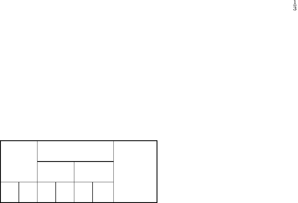
(700 °F) or higher. Corrections should be made for errors introduced by the high temperature. Table 1 lists several
correction factors for ultrasonic thickness measurements in carbon steels at elevated temperatures. Additional information
can be found in Ref 15.
Table 1 Correction factors for ultrasonic thickness measurements in carbon steels at elevated temperatures
Measurement Temperature
Ultrasonic Micrometer
°C °F mm in. mm in.
Correction factor

40 100 13.11
0.516
13.11
0.516
0
95 200 13.15
0.518
13.13
0.517
0.998
150 300 13.26
0.522
13.14
0.5175
0.991
205 400 13.33
0.525
13.15
0.518
0.987
260 500 13.36
0.526
13.16
0.5185
0.986
315 600 13.41
0.528
13.18
0.519
0.983
370 700 13.46
0.520
13.20
0.520
0.981
400 750 13.51
0.532
13.26
0.522 0.981
Source: Ref 15
Flaw detection prior to fabrication is usually concerned with the inspection of steel or alloy plates for internal
laminations, segregates, and similar discontinuities because they can be quite harmful under certain operating conditions.
For example, hydrogen blistering can occur at a lamination, and stress-corrosion cracking, fatigue, intergranular
corrosion, and hydrogen embrittlement are often accelerated by such discontinuities.
For flaw detection, a continuous-scan method is often used, in which the transducer is carried on a rigid carriage and the
ultrasound waves are coupled into the plate by a stream of water. In some applications, the plate can be immersed, which
simplifies the operation. To eliminate some of the human errors, a flaw-alarm system is set up so that a flaw of
predetermined size will trigger a warning of some kind.
For the inspection of a weld, the weld shape may be such that the use of longitudinal waves is impossible, and a flaw such
as a crack at the fusion zone probably will not present enough reflective area to be detected from directly above it.
Nozzles located in hemispherical heads present special problems, and special techniques must be used to ensure a
thorough inspection. Using shear waves, the sound can be directed into a suspect area from almost any angle. Large-scale
drawings of the suspect area are needed to lay out correct angles and distances for the transducers (Fig. 9). For
components having a complicated design, a plastic model can be an aid to better visualization of the sound path and
angles of reflection. Thought given to the best approach and techniques can save hours in inspection and can ensure
proper coverage. Angle transducers of 45 and 60° will detect almost any weld discontinuity, particularly if both internal
and external surfaces are available for inspection. If the internal surface is not available, the nozzle can be filled with
water and a search unit lowered to the correct depth to inspect the weld. The search unit can be adjusted to any angle and
turned from side to side while in use. A plastic wedge on the search unit can be used to direct the sound beam through the
nozzle body. Correctly angled, the beam will be intercepted by any radial flaw in the nozzle body and can also reach the
attachment weld on the far side. The wedge can be shaped on a test block duplicating a nozzle section, and the sound path
can be determined by through transmission (one transducer transmitting the signal and another, placed opposite, receiving
the signal).
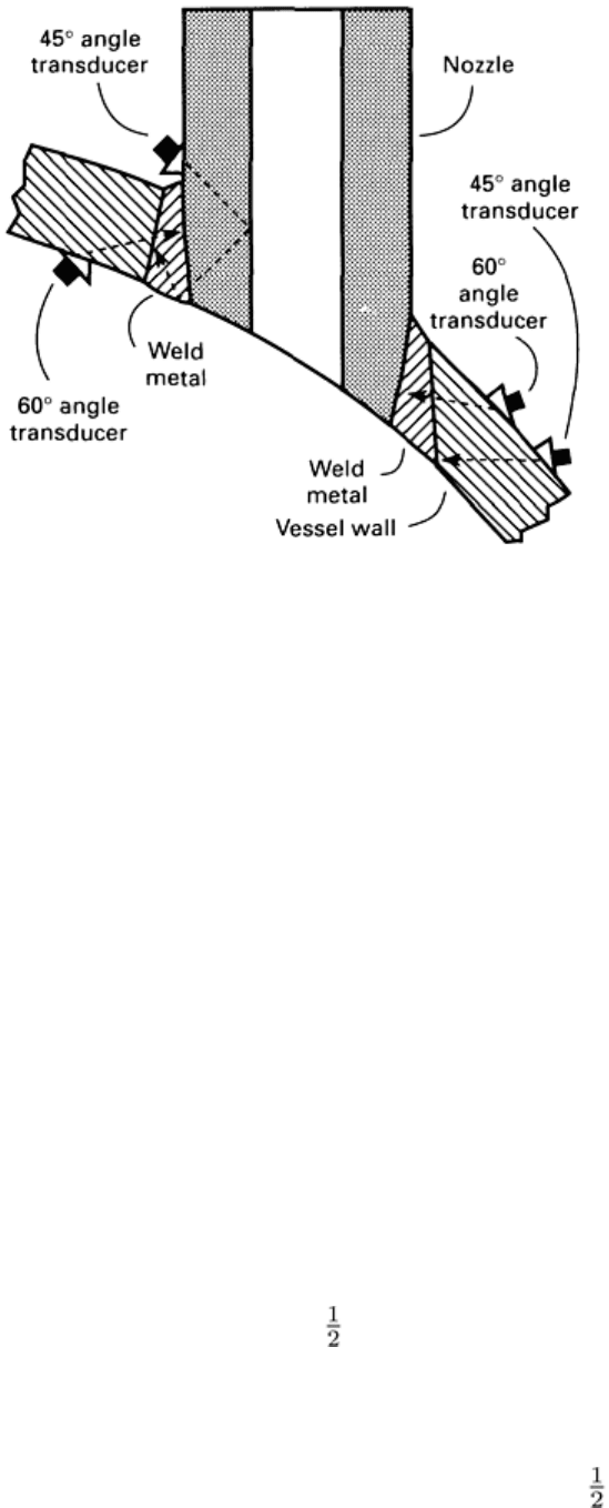
Fig. 9 Typical layout used on large-scale drawings to determine transducer angles and
distances for inspection
of difficult-to-reach weld areas
Shear wave search units intended for inspection at high temperatures may have the plastic wedge made of a special heat-
resistant material. Such materials usually increase attenuation, and calibration must be made at temperatures close to that
of the surface of the part being inspected if detection of a flaw of given size is to be ensured.
Examples of Application. The use of ultrasonics in the detection of discontinuities in a pressure vessel is discussed in
the following examples. Additional information on in-service inspection is presented in the following section of this
article.
Example 3: Use of Ultrasonic Inspection to Detect Creep Rupture in Stainless
Steel Headers of an Ammonia-Plant Reformer Furnace
(Ref 16). A leak was detected in one of the coils in the radiant section of a primary reformer furnace used in an ammonia
plant. Furnace temperatures were reduced immediately, but it was necessary to continue firing of the furnace at about 540
to 595 °C (1000 to 1100 °F) for 16 h to reduce the catalyst. Subsequent shutdown inspection revealed that the bottom of
one of seven outlet headers had ruptured, causing a section about 100 mm (4 in.) wide by 460 mm (18 in.) long to fall to
the furnace floor. The outlet headers were 100 mm (4 in.) nominal diameter schedule 120 (11 mm, or 0.438 in., wall) pipe
about 10 m (34 ft) long and were made of ASME SA-452, grade TP316H, stainless steel. In the absence of hot spots, the
surface of the outer tube ranged from 845 to 855 °C (1550 to 1575 °F). The unit had been on stream about 29,000 h prior
to failure.
To get the unit back in service quickly, a section about 1.4 m (4 ft) in length was replaced. The amount of header metal
replaced was based on results from both visual and liquid penetrant inspections of the outer surface of the header. The
inner surface, where accessible, was also checked visually and by liquid penetrant inspection. The six other headers were
inspected at selected locations, and no surface cracks were detected.
Investigation of the Removed Section. Metallographic examination of the 1.4 m (4 ft) section of the header that
had been removed revealed that it had failed as a result of intergranular fissuring and oxidation, commonly termed creep
rupture. Severe intergranular fissuring was found throughout the cross section of the header sample. Primary cracking
occurred intergranularly through the grain boundaries, typical of high-temperature fissuring. Close observation of the
crack paths linking some of the larger fissures, however, did reveal local areas having grains that were much smaller than

those of the header metal. The presence of these very small grains could only be the result of cold deformation and
subsequent recrystallization at elevated temperatures. Therefore, some plastic strain and cracking had occurred at
temperatures well below the operating temperature, apparently as a result of thermal expansion and contraction stresses
during startups and shutdowns, and then the cold-strained areas had recrystallized subsequently when they were reheated
to the service temperature. Therefore, it follows that all of the fissuring did not take place during any one operating
period. Also, the microstructure in the ruptured area gave the following evidence that the header metal had not been
subjected to gross overheating in service:
• The header metal still had a general grain structure that would be c
lassified as being of fine size, while
severe grain coarsening would have occurred if the header metal had been heated at temperatures
between 1095 and 1315 °C (2000 and 2400 °F)
• The microconstituents present in the grains would have been dissolved at gro
ssly elevated temperatures
and would have been of much finer size if they had subsequently precipitated out of solid solution
during the final 16 h of firing at 595 °C (1100 °F) to reduce catalyst
It was concluded from this investigation of the ruptured area that the header had failed by conventional long-time creep
rupture as a result of exposure to operating temperatures probably between 900 and 955 °C (1650 and 1750 °F), rather
than by short-time exposure at grossly elevated temperatures. It was suspected that the furnace headers might not be as
sound as the visual and liquid penetrant inspections of the surface metal had indicated; therefore, three ring sections from
the removed 1.4 in (4 ft) long header section were selected for further study. The sections were taken from the ruptured
area (sample A), from a slightly bulged but nonruptured area (sample B), and from visually sound metal about 0.6 m (2 ft)
from the rupture (sample C).
Inspection of the three samples revealed the presence of pinhead-size intergranular fissures throughout the cross sections
of samples B and C (Fig. 10). This indicated that the header metal at these locations had been in an advanced stage of
creep rupture even though the fissures or voids were of small size. Sample C had fewer pinhead voids than sample B.
With continued service, the pinhead voids would have increased in number and grown in size and eventually would have
linked up and caused failure. Generally, the microstructure of the inner surface of the header in the area of rupture
(sample A, Fig. 10a) contained intergranular fissures (black areas), a relatively fine grain structure, precipitated
microconstituents in the grains, and considerable amounts of carbides in the nonfissured grain boundaries. The presence
of the carbides was evidence of carbon pickup in service.
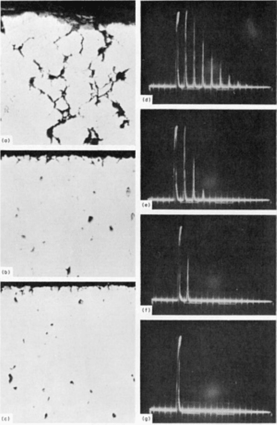
Fig. 10 Unetched microscopic appearance of three samples of failed pipe from a reformer-
furnace header of
TP316H stainless steel pipe and corresponding ultrasound responses of the three samples compare
d to the
response of unused pipe. Micrographs of (a) sample A, (b) sample B, and (c) sample C. All 100×. Black voids
are intergranular fissures. Ultrasound responses for (d) unused pipe, (e) sample C, (f) sample B, and (g)
sample A. Strong reflections were
obtained from the unused pipe, and attenuation increased as the number of
fissures increased in damaged pipes.
Sample C had been removed from a visually undamaged header area located about 0.6 m (2 ft) from the rupture and about
250 mm (10 in.) from the sound end of the header section. It was considered possible that the header metal that was in
service and only 250 mm (10 in.) away from the area of sample C was also in an advanced stage of creep rupture. It
appeared probable that localized areas of the other six headers were in critical condition or that the problem was of a
general nature. Therefore, it was decided that the remaining headers in service should be inspected as soon as possible
because obtaining replacement parts might require several months of lead time. An ultrasonic attenuation method was
considered to be the only possible nondestructive method for this evaluation, and development of a suitable system for
use in the field was undertaken.
Ultrasonic Inspection Equipment and Standards. It was determined that optimum results that permitted the
determination of changes in attenuation as a function of the number of cracks present required the use of a 22-MHz search
unit in conjunction with a pulse-echo instrument. To minimize surface effects and curvature, a short water column was
used to couple the sonic energy to the headers. This water column was enclosed in a Lucite cylinder 32 mm (1.25 in.)
long with a 6 mm (0.25 in.) thick polyurethane-foam gasket at the bottom. The pliable gasket conformed to the curved
surfaces of the header. The search unit was held in position by a setscrew. Water flowed through the unit by gravity and
escaped through a small hole in the Lucite cylinder at a point just above the front surface of the transducer.
A section of unused type 316H stainless steel pipe and the three sections of header metal from the rupture area were used
for reference. Strong reflections were obtained from the undamaged pipe (Fig. 10); increased attenuation was obtained
from damaged piping as the number of cracks increased, as indicated by the ultrasonic responses in Fig. 10(e) to 10(g).
The results of the test correlated well with the characterization of the number of cracks observed by optical microscopy
(Fig. 10a to 10c). Approximately 1 year later, with 37,336 h on stream, the plant was shut down, and in-service inspection
was conducted using the ultrasonic technique developed.
In-Service Ultrasonic Inspection. The standards and equipment used to develop the ultrasonic technique were used
for the field inspection of the reformer furnace. Ultrasonic readings were taken on the horizontal header metal between
each vertical tube and on both sides of any header welds. Over 350 readings were made. In addition, at some locations,
readings were taken on the top, bottom, and sides. It was found that the headers all contained internal voids throughout
their lengths, of varying numbers between those of samples B and C. The inspection results indicated that all headers
were in an advanced stage of creep rupture (stress rupture) but that no areas had fissured to a degree that they needed
immediate replacement. The replacement piping that had been installed during the previous shutdown 13 months earlier
gave a "good" signal similar to unused material. The technique developed for the field survey was not adaptable for
determining the conditions of the welded joints, so none of the readings represents welds.
On the basis of results of the in-service inspection, two conclusions were reached. First, the furnace was deemed
serviceable, and second, in the absence of local hot spots, the headers would survive for a reasonable period of time.
Example 4: Ultrasonic Inspection for Creep Fissures in Reformer-Furnace Tubes
(Ref 17). Preliminary studies were made to establish whether sound would transmit through cast heat-resistant alloy HK-
40 tubes from a reformer furnace. Several tests were conducted, and the most likely method was found to be the
measurement of attenuation losses in a dual sensor using the through transmission method in an immersion tank. The tests
showed that sound would transmit in HK-40 tubes with the use of a low-frequency transducer. Also, the rough outer
surface of a centrifugal casting was the significant factor, rather than poor transmission in the large-grain cast
microstructure. Immersion methods minimized the surface roughness condition and provided sufficient acoustic energy in
the tubes. A dual search unit, with a sending transducer and a receiving transducer to produce a refracted-angle sound
beam, was the best means for passing sound through the tube and across the plane of fissure formation. The attenuation of
this beam, measured by the receiver, was a measure of fissure density.
Figure 11 shows the results of ultrasonic C-scan amplitude recordings on three sample tubes in an immersion tank. By
moving the dual search unit at a constant speed longitudinally along the tube and indexing at the end of each traverse, and
continuously recording the received ultrasonic signal, attenuation patterns in fissured tubes were recorded. Sample tubes
with known fissures showed that some or all of the sound transmission was interrupted, depending on the density of the
fissures (compare Fig. 11a and 11b). Sample tubes with no fissures showed full sound transmission (Fig. 11c).
