ASM Metals HandBook Vol. 17 - Nondestructive Evaluation and Quality Control
Подождите немного. Документ загружается.

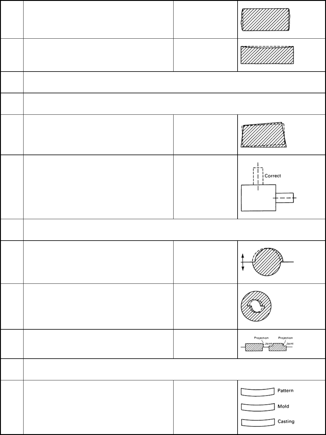
F 125 Excessive metal thickness at irregular locations on casting
exterior
Soft or insufficient
ramming, mold-wall
movement
F 126 Thin casting walls over general area, especially on horizontal
surfaces
Distorted casting
F 200:
Casting shape incorrect overall or in certain locations
F 210:
Pattern incorrect
F 211 Casting does not conform to the drawing shape in some or
many respects; same is true of pattern
Pattern error
F 212 Casting shape is different from drawing in a particular area;
pattern is correct
Pattern mounting error
F 220:
Shift or Mismatch
F 221 Casting appears to have been subjected to a shearling action
in the plane of the parting line
Shift
F 222 Variation in shape of an internal casting cavity along the
parting line of the core
Shifted core
F 223 Irregular projections on vertical surfaces, generally on one
side only in the vicinity of the parting line
Ramoff, ramaway
F 230:
Deformations from correct shape
F 231 Deformation with respect to drawing proportional for casting,
mold, and pattern
Deformed pattern
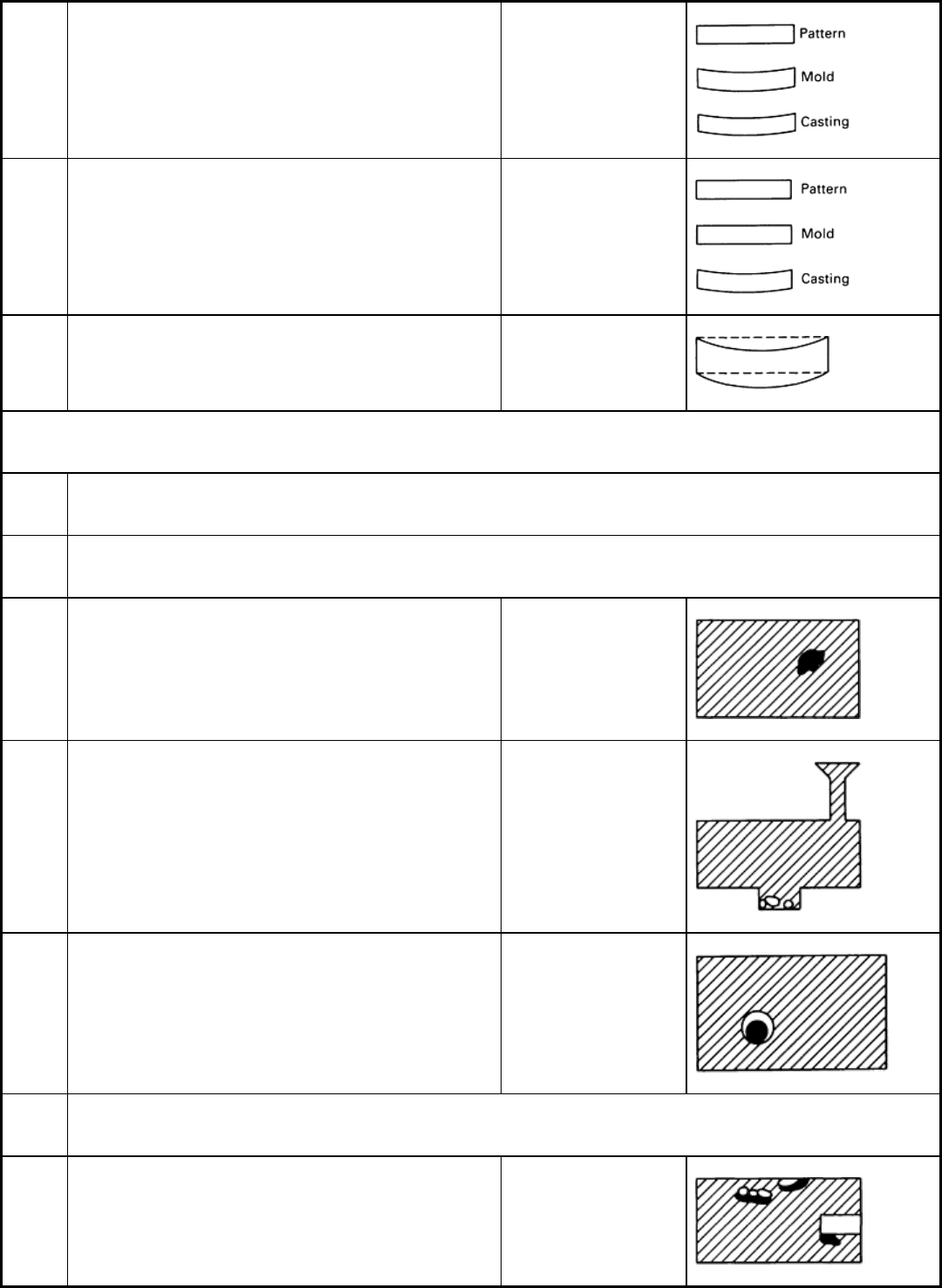
F 232 Deformation with respect to drawing proportional for casting
and mold; pattern conforms to drawing
Deformed mold, mold
creep, springback
F 233 Casting deformed with respect to drawing; pattern and mold
conform to drawing
Casting distortion
F 234 Casting deformed with respect to drawing after storage,
annealing, machining
Warped casting
Inclusions or Structural Anomalies
G 100:
Inclusions
G 110:
Metallic inclusions
G
111
(a)
Metallic inclusions whose appearance, chemical analysis or
structural examination show to be caused by an element
foreign to the alloy
Metallic inclusions
G
112
(a)
Metallic inclusions of the same chemical composition as the
base metal; generally spherical and often coated with oxide
Cold shot
G 113 Spherical metallic inclusions inside blowholes or other
cavities or in surface depressions (see A 311). Composition
approximates that of the alloy cast but nearer to that of a
eutectic
Internal sweating,
phosphide sweat
G 120:
Nonmetallic inclusions; slag, dross, flux
G
121
(a)
Nonmetallic inclusions whose appearance or analysis shows
they arise from melting slags, products of metal treatment or
fluxes
Slag, dross or flux
inclusions, ceroxides
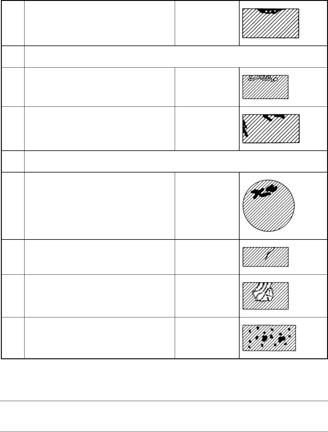
G
122
(a)
Nonmetallic inclusions generally impregnated with gas and
accompanied by blowholes (B 113)
Slag blowhole defect
G 130:
Nonmetallic inclusions; mold or core materials
G
131
(a)
Sand inclusions, generally very close to the surface of the
casting
Sand inclusions
G
132
(a)
Inclusions of mold blacking or dressing, generally very close
to the casting surface
Blacking or refractory
coating inclusions
G 140:
Nonmetallic inclusions; oxides and reaction products
G 141 Clearly defined, irregular black spots on the fractured surface
of ductile cast iron
Black spots
G
142
(a)
Inclusions in the form of oxide skins, most often causing a
localized seam
Oxide inclusion or skins,
seams
G
143
(a)
Folded films of graphitic luster in the wall of the casting Lustrous carbon films,
or kish tracks
G 144 Hard inclusions in permanent molded and die cast
aluminum alloys
Hard spots
(a)
Defects that under some circumstances could contribute, either directly or indirectly, to casting failures. Adapted from International Atlas of
Casting Defects, American Foundrymen's Society, Des Plaines, IL
Nondestructive Inspection of Castings
By the ASM Committee on Nondestructive Inspection of Castings
*

Common Inspection Procedures
The inspection of castings is most often limited to visual and dimensional inspections, weight testing, and hardness
testing. However, for castings that are to be used in critical applications, such as automotive or aerospace components,
additional methods of nondestructive inspection are used to determine and to control casting quality.
Visual inspection of each casting ensures that none of its features has been omitted or malformed by molding errors,
short running, or mistakes in cleaning. Most surface defects and roughness can be observed at this stage.
Initial sample castings from new pattern equipment should be carefully inspected for obvious defects. Liquid penetrant
inspection can be used to detect surface defects. Such casting imperfections as shrinks, cracks, blows, or dross usually
indicate the need for adjustment in the gating or foundry techniques. If the casting appears to be satisfactory upon visual
inspection, internal quality can be checked by radiographic and ultrasonic inspection.
The first visual inspection operation on the production casting is usually performed immediately after shakeout or
knockout of the casting, ensuring that major visible imperfections are detected as quickly as possible. This information,
promptly relayed to the foundry, permits early corrective action to be taken with a minimum of scrap loss. The size and
complexity of some sand castings require that the gates and risers be removed to permit proper inspection of the casting.
Many castings that contain numerous internal cores or have close dimensional tolerances require a rapid, but fairly
accurate check of critical wall dimensions. In some cases, an indicating-type caliper gage is suitable for this work, and
special types are available for casting shapes that do not lend themselves to the standard types. Ultrasonic inspection is
also used to determine wall thickness in such components as cored turbine blades made by investment casting. New
developments in visual inspection procedures for examining component appearance are mainly based on vision systems
that use electronic cameras coupled to computer-assisted image-processing systems (Ref 1).
With the development of high-sensitivity cameras having exposure times of s, components can be inspected on
moving belts. Flexibility for examining three-dimensional components can be achieved with an array of cameras
multiplexed to a common image processor or with a computer-controlled camera scanning system. Such systems have
been successfully applied to the inspection of printed circuit boards in the electronics industry and engineering
subassemblies in automobile manufacture. These tests usually operate on a go/no-go basis; either the assembly is
complete with connections correctly made or it is not correct. This is a far easier task than evaluating casting quality.
Studies that have been carried out to assess the possibility of extending such methods to iron castings have not given
encouraging results. Contrast between defective and nondefective areas is low, illumination is critical, and consistent
standards of inspection are difficult to maintain because of differences in reflectivity of the casting surfaces depending on
whether or not they have been recently shotblasted. Even the simple task of identifying castings to determine their type is
best carried out by examining their backlighted silhouette, and this provides no advantage in examining their quality.
Dimensional Inspection. Consistency of dimensions is an inescapable requirement of premium-quality castings
supplied as near-net shape components on which subsequent high-speed machining operations are to be carried out (Ref
1). Customers will not accept increased machining costs due to inconsistencies in dimensions nor will they tolerate
damage to flexible machining systems or transfer times resulting from poor control and inspection in foundries.
Variations in dimensions represent one of the most common complaints with regard to the machinability of iron castings.
Prevention is within the control of foundries. Differences in pattern size when using multipattern plates can be virtually
eliminated by the use of computer-aided design and manufacturing methods and computer numerical control machines in
patternmaking (see the article "Patterns and Patternmaking" in Casting, Volume 15 of ASM Handbook, formerly 9th
Edition Metals Handbook). Better process control and methoding can eliminate variations in dimensions due to changes
in metal composition or feeding methods. Variations in mold rigidity, caused by inadequate compaction with green sand,
or the use of cold sand or insufficient curing times with cold-setting systems, which cause casting dimensions to fall
outside the preset tolerance limits, can be greatly reduced by good molding and coremaking practices (see the articles
"Sand Molding" and "Coremaking" in Casting, Volume 15 of ASM Handbook, formerly 9th Edition Metals Handbook).
Because the dimensions and weight of iron castings are directly related to their soundness and are dependent on mold
rigidity, the measurement of size or weight provides a simple test for checking casting integrity and for monitoring the
consistency of the moldmaking process (see the section "Weight Testing" in this article).
Casting dimensions are usually checked with dial gages, vernier calipers, micrometers, or vertical height gages, which
may be hand held or incorporated into acceptance fixtures. Wall thickness measurements can be made with small hand-

held ultrasonic thickness gages. Under ideal conditions, the accuracy of these instruments is claimed to be ±0.01 mm
(±0.0004 in.), but this is rarely achieved in practice because the surfaces are not parallel and are not machined.
Instruments are available that display variations in thickness from some preset standard and provide a digital readout and
a permanent record of results for statistical analysis.
Developments lie in the use of measuring systems employing capacitance, electrical contact, or linear displacement
transducers. Such systems are capable of high accuracy and the output can be linked directly to microcomputers for data
recording and statistical analysis to meet the requirements of statistical process control. The use of computer-aided
dimensional control and statistical process control is discussed later in this article.
Laser methods of measurement using beam displacement or time-lapse techniques are available for use in machine shops
where accurate measurement is required for control of automatic machining processes. At present, they are generally not
well suited for measuring castings, because of their high cost and because it is difficult to make precise measurements on
components having a complex shape with curved or as-cast surfaces. As these laser methods become more widely used in
other industries, lower-cost systems will become available, and these might be developed for foundry use (see the article
"Laser Inspection" in this Volume).
Weight Testing. Many intricately cored castings are extremely difficult to measure accurately, particularly the internal
sections. It is important to ensure that these sections are correct in thickness for three main reasons:
• There should be no additional weight that would make the finished product heavier than permissible
• Sections must not be thinner than designed so as not to decrease the strength of the casting
•
If hollow cavities have been reduced in area by increasing the metal thickness of the sections, any flow
of liquid or gases is reduced
A ready means of testing for these discrepancies is by accurately weighing each casting or by measuring the displacement
caused by immersing the casting in a liquid-filled measuring jar or vessel. In certain cases in which extreme accuracy is
demanded, a tolerance of only ±1% of a given weight may be allowed.
Hardness testing is often used to verify the effectiveness of the heat treatment applied to actual castings. Its general
correlation with the tensile strength of many ferrous alloys allows a rough prediction of tensile strength to be made.
The Brinell hardness test is most frequently used for casting alloys. A combination of large-diameter ball (5 or 10 mm)
and heavy load (500 to 3000 kgf) is preferred for the most effective representation because a deep impression minimizes
the influence of the immediate surface layer and of the relatively coarse microstructure. The Brinell hardness test is
unsuitable for use at high hardness levels (above 600 HB), because distortion of the ball indenter can affect the shape of
the indentation.
Either the Rockwell or the Vickers (136° diamond pyramid) hardness test is used for alloys of extreme hardness or for
high-quality and precision castings in which the large Brinell indentation cannot be tolerated. Because of the very small
indentations produced in Rockwell and Vickers tests, which use loads of 150 kg or less, results must be based on the
average of a number of determinations. Portable hardness testers or ultrasonic microhardness testers can be used on large
castings that cannot be placed on the platform of a bench-type machine. More detailed information on hardness testing is
available in Mechanical Testing, Volume 8 of ASM Handbook, formerly 9th Edition Metals Handbook.
The hardness of ferrous castings can be determined from the sonic velocity of the metal if all other test conditions remain
constant. This has been demonstrated on chilled rolls in determining the average hardness of the core.
Reference cited in this section
1.
P.J. Rickards, Progress
in Guaranteeing Quality Through Nondestructive Methods of Evaluation,
Foundryman Int., April 1988, p 196-209

Nondestructive Inspection of Castings
By the ASM Committee on Nondestructive Inspection of Castings
*
Computer-Aided Dimensional Inspection
The use of computer equipment in foundry inspection operations is finding more acceptance as the power and utility of
available hardware and software increase. The computerization of operations can reduce the man-hours required for
inspection tasks, can increase accuracy, and can allow the analysis of data in ways that are not possible or practical with
manual operations. Perhaps the best example of this, given the currently available equipment, is the application of
computer technology to the dimensional inspection of castings.
Importance of Dimensional Inspection. One of the most critical determinants of casting quality in the eyes of the
casting buyer is dimensional accuracy. Parts that are within dimensional tolerances, given the absence of other casting
defects, can be machined, assembled, and used for their intended functions with minimal testing and inspection costs.
Major casting buyers are therefore demanding statistical evidence that dimensional tolerances are being maintained. In
addition, the statistical analysis of in-house processes has been demonstrated to be effective in keeping those processes
under control, thus reducing scrap and rework costs.
The application of computer equipment to the collection and analysis of dimensional inspection data can increase the
amount of inspection that can be performed and decrease the time required to record and analyze the results. This
furnishes control information for making adjustments to tooling on the foundry floor and statistical information for
reporting to customers on the dimensional accuracy of parts. Additional information on dimensional accuracy in castings
can be found in the article "Dimensional Tolerances and Allowances" in Casting, Volume 15 of ASM Handbook, formerly
9th Edition Metals Handbook.
Typical Equipment. A typical installation for the dimensional inspection of castings consists of an electronic
coordinate measuring machine, a microcomputer interfaced to the coordinate measuring machine controller with a data
transfer cable, and a software system for the microcomputer (Fig. 1). The software system should be capable of
controlling the functions and memory storage of the coordinate measuring machine as well as recalling and analyzing the
data it collects. The software serves as the main control element for the dimensional inspection and statistical reporting of
results. Such software can be purchased or, if the expertise is available, developed in-house for highly specialized
requirements.
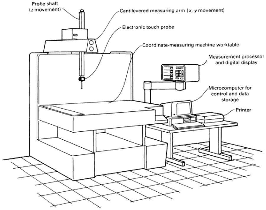
Fig. 1 Equipment used in a typical installation for the computer-
aided dimensional inspection of castings
showing a coordinate measuring machine and microcomputer
Coordinate measuring machines typically record dimensions along three axes from data points specified by the user.
Depending on the sophistication of the controller, such functions as center and diameter finds for circular features and the
electronic rotation of measurement planes can be performed. Complex geometric constructions, such as the intersection
points of lines and planes and out-of-roundness measurements, are typically off-loaded for calculation into the
microcomputer. The contact probe of the coordinate measuring machine can be manipulated manually, or in the case of
direct computer controlled machines, the probe can be driven by servomotors to perform the part measurement with little
operator intervention. More detailed information on these machines can be found in the article "Coordinate Measuring
Machines" in this Volume.
The Measurement Process. Figure 2 illustrates the general procedure that is followed in applying semiautomatic
dimensional inspection to a given part. The first step is to identify the critical part dimensions that are to be measured and
tracked. Nominal dimensions and tolerances are usually taken from the customer's specifications and blueprints.
Dimensions that are useful in controlling the foundry process can also be selected. A data base file, including a
description and tolerance limits for each dimension to be checked, is then created using the microcomputer software
system.
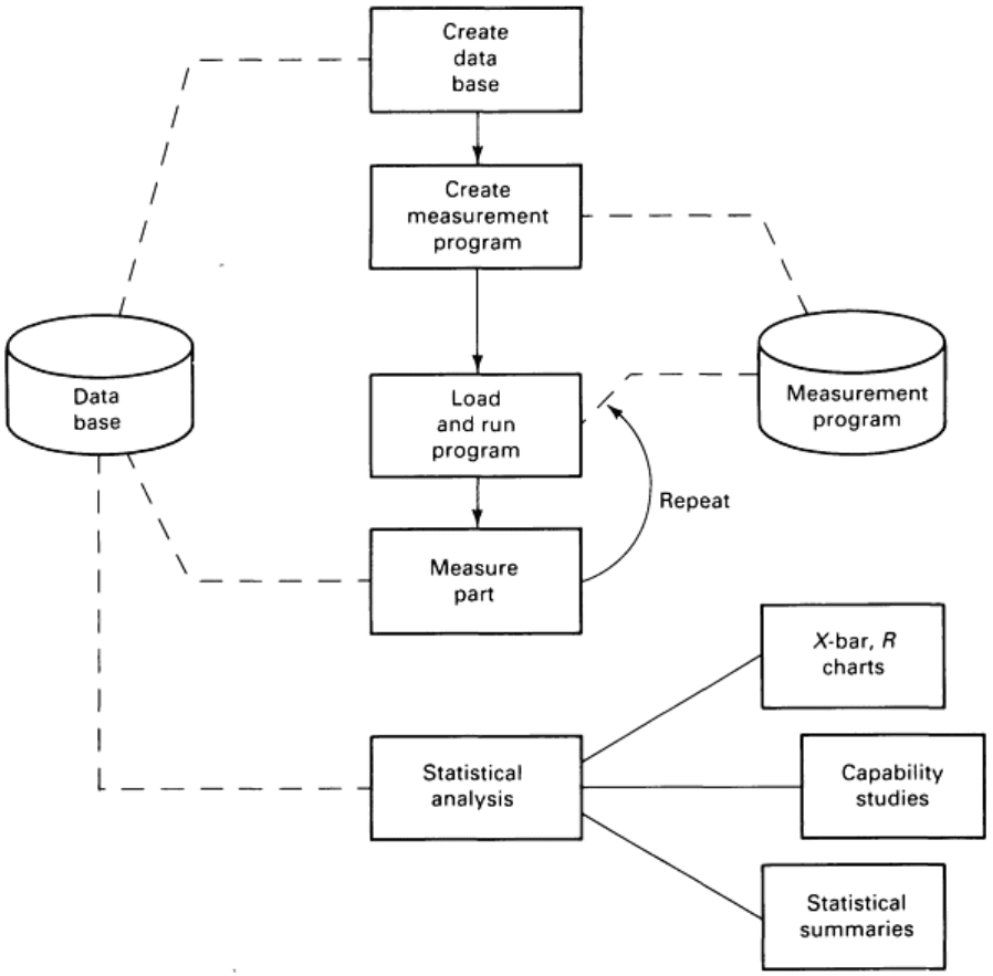
Fig. 2 Flowchart showing typical sequence of operations for computer-aided dimensional inspection
The next step in the setup process is to develop a set of instructions for measuring the part with the coordinate measuring
machine. The instructions consist of commands that the coordinate measuring machine uses to establish reference planes
and to measure such features as the center points of circular holes.
This measurement program can be entered in either of two ways. In the first method, the operator simply types in a list of
commands that he wants the coordinate measuring machine to execute and that give the required dimensions as defined in
the part data base. The second method uses a teach mode. The operator actually places a part on the worktable of the
coordinate measuring machine and checks it in the proper sequence, while the computer monitors the process and stores
the sequence of commands used. In either case, the result is a measurement program stored on the microcomputer that
defines in precise detail how the part is to be measured. Special commands can also be included in the measurement
program to display operator instructions on the computer screen while the part is being measured.
In developing the measurement program, consideration must be given to the particular requirements of the part being
measured. Customer prints will normally show datum planes from which measurements are to be made. When using a
cast surface to establish a datum plane, it is good practice to probe a number of points on the surface and to allow the
computer to establish a best-fit plane through the points. Similarly, the center points of cast holes can best be found by
probing multiple points around the circumference of the hole. Machined features can generally be measured with fewer
probe contacts. When measuring complex castings, maximum use should be made of the ability of the coordinate
measuring machine to electronically rotate measurement planes without physically moving the part; unclamping and
turning a part will lower the accuracy of the overall layout.
Once the setup process is complete, the dimensional inspection of parts from the foundry begins. Based on statistical
considerations, a sampling procedure and frequency must be developed. Parts are then selected at random from the
process according to the agreed-upon frequency. The parts are brought to the coordinate measuring machine, and the
operator calls up the measurement program for that part and executes it. As the part is measured, the dimensions are sent
from the coordinate measuring machine to the data base on the microcomputer. Once the measurement process is
completed, information such as mold number, shift, date, and serial number should be entered by the operator so that this
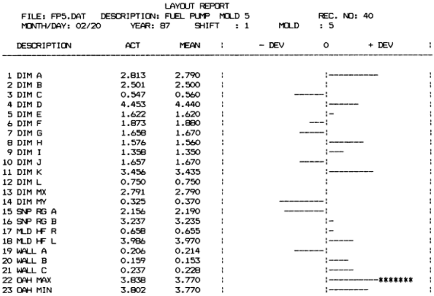
particular set of dimensions can be identified later. A layout report can then be generated to show how well the measured
part checked out relative to the specified dimensions and tolerances. Figure 3 shows a sample report in the form of a bar
graph, in which any deviation from print tolerance appears as a line of dashes to the left or right of center. A deviation
outside of tolerance limits displays asterisks to flag its condition. Such a report is useful in that it gives a quick visual
indication of the measurement of one casting.
Fig. 3 Example layout re
port showing all dimensions measured on a single casting, with visual indication of
deviations from print mean. Note out-of-tolerance condition indicated by asterisks.
Statistical analysis permits the mathematical prediction of the characteristics of all the parts produced by measuring
only a sample of those parts (the principles and applications of statistics in industrial environments are discussed in the
article "Statistical Quality Design and Control" in this Volume). All processes are subject to some amount of natural
variation; in most processes, this variation follows a normal distribution (the familiar bell-shaped curve) when the
probability of occurrence is plotted against the range of possible values. Standard deviation, a measure of the distance
from center on the probability curve, is the principal means of expressing the range of measured values. For example, a
spread of six standard deviations (plus or minus three standard deviations on either side of the measured mean) represents
the range within which one would expect to find 99.73% of observed measurements for a normal process. This allows the
natural variation inherent in the process to be quantified.
Control Charts. With statistical software incorporated into the microcomputer system, the results of numerous
measurements of the same part can be analyzed to determine, first, how well the process is staying in control, that is,
whether the natural variations occurring in a given measurement are within control limits and whether any identifiable
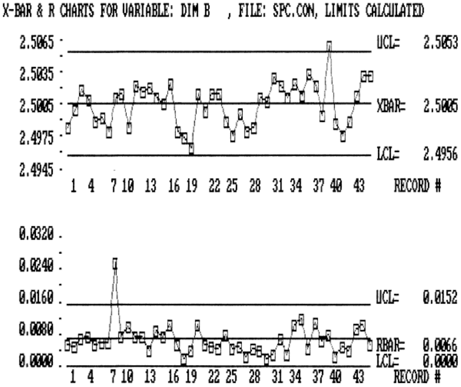
trends are occurring. This is done by using a control chart (Fig. 4), which displays the average values and ranges of
groups of measurements plotted against time. Single-value charts with a moving range can also be helpful. The control
limits can also be calculated and displayed. With the computer, this type of graph can be generated within seconds.
Analysis of the graph may show a developing trend that can be corrected by adjusting the tooling before out-of-tolerance
parts are made.
Fig. 4 Control chart with average of groups of measurements (X
values) plotted above and ranges within the
groups (R) plotted below. Control limits have been calculated and placed on the chart by the computer.
Statistical Summary Report. The second type of analysis shows the capability of the process, that is, how the range
of natural variation (as measured by a specified multiple of the standard deviation) compares with the tolerance range
specified for a given dimension. An example of a useful report of this type is shown in Fig. 5. This information is of great
interest both to the customer and the process engineer because it indicates whether or not the process being used to
produce the part can hold the dimensions within the required tolerance limits. The user must be aware that different
methods of capability analysis are used by different casting buyers, so the software should be flexible enough to
accommodate the various methods of calculation that might be required.
