ASM Metals HandBook Vol. 17 - Nondestructive Evaluation and Quality Control
Подождите немного. Документ загружается.

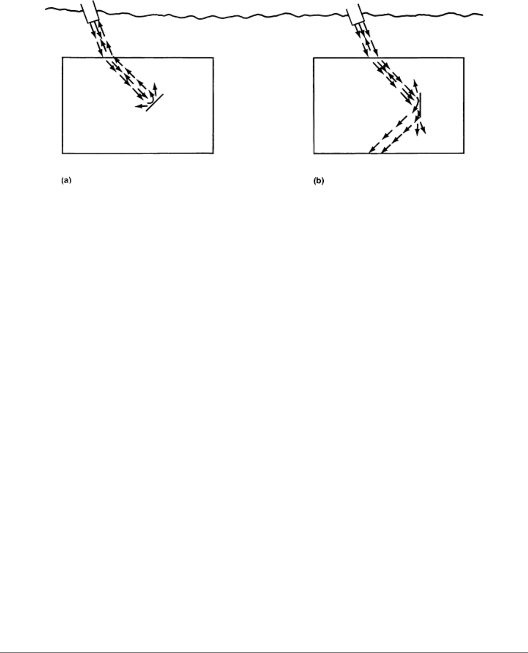
Fig. 19
Comparisons of discontinuities at normal orientation versus radial orientation. (a) Discontinuity normal
to sound energy, almost total reflection of energy back toward transducer. (b) Discontinuity at 0° wi
th respect
to 45° sound energy path, almost no energy reflected back toward transducer
Complex shapes are difficult to inspect ultrasonically because of the problems associated with sound-entry angle. Most
ultrasonic inspection of forgings uses techniques that send waves into the forging perpendicular to the surface. Radii,
fillets, and similar configurations must receive special treatment if all areas of the forging must be inspected. The special
treatment involves the use of a standoff that has an end contoured to fit the inspection surface or the use of a small-
diameter or focused transducer.
Application. In certain cases, where the end use of a forging is considered critical, ultrasonic inspection is used to
inspect the wrought material before it is worked. Surface or internal flaws that are not detected before a billet is forged
may not be detected in the final forging and will therefore be present in the finished part. Ultrasonic inspection is often
used as part of a completely diagnostic inspection of a forging from newly designed dies, where use of the finished part
does not warrant inspection of every part.
Quality control measures often include the ultrasonic inspection of random samples from a particular forging. This
provides the necessary assurance that the process is under control and that variables affecting internal quality have not
been inadvertently introduced.
Ultrasonic inspection is often used in the further evaluation of flaws detected by other nondestructive methods. This
reduces the possibility that a particular forging will be unsuitable for its intended service.
Ultrasonic inspection can be used on every forging to validate its integrity for extremely rigorous requirements. This
applies in particular to forgings for nuclear and aerospace applications, where rigid standards of acceptance have been
established. Standards and criteria have been set up to detect material inclusions, internal voids, laminations, and other
conditions. In addition, the inspection of every forging by ultrasonics has been effective in detecting excessive grain size
and other structural conditions.
Ultrasonic inspection is often used to qualify a particular lot of forgings that has been subjected to certain variations in
approved processing procedures. A notable instance is the use of ultrasonics to determine the presence of thermal flakes
or in locating quench cracks.
Note cited in this section
*
The term dead zone refers to the depth below the entry surface where any echoes from flaws cannot be
detected because
they are masked by the trailing edge of the transmitted pulse. The dead zone depends on

sound velocity, test frequency, and pulse length and is different for different combinations of test metal,
transducer, and test instrument.
Nondestructive Inspection of Forgings
Basic Procedures for Ultrasonic Inspection
Many specific procedures have been developed for the inspection of forgings by ultrasonics. The basic procedures
described here are based on those developed for use in a specific plant.
Forgings of regular (symmetrical) shape are ultrasonically inspected at final inspection (prior to shipment). If possible, the
entire forging is ultrasonically inspected.
Irregularly shaped forgings, which have a configuration that precludes complete inspection prior to shipment, are
ultrasonically examined at the latest stage of processing that will permit examination of the entire forging (preliminary
inspection). These complex shapes are then reexamined to the extent practical before shipping (final inspection). To
ensure complete inspection coverage of the forging, the transducer is indexed with at least 15% overlap with each pass.
The rate of scanning does not exceed 150 mm/s (6 in./s).
The surface roughness of forgings from which ultrasonic examination is conducted should be no greater than 6 μm (250
μin.), unless otherwise specified. The forging surfaces should also be free of extraneous material, such as loose scale,
paint, dirt, or other contaminants.
Equipment
An ultrasonic, pulsed, reflection-type instrument is used to inspect forgings. The instrument is capable of operating at
three or more frequencies; for example, 1.0, 2.25, and 5.0 MHz. The instrument provides a linear presentation (within
±5%) to approximately 75% of the screen height or a minimum of 40 mm (1 in.). Signal attenuators and calibrated gain
control, if used, are accurate over the range used to ±10% of the nominal attenuation ratio. Forgings are examined by the
longitudinal wave technique at 2.25 MHz unless adequate penetration cannot be obtained, in which case the inspection is
conducted at 1.0 MHz.
Longitudinal Wave Ultrasonic Inspection
Where possible, all forgings are scanned in two directions perpendicular to each other. Disk (pancake) forgings are
examined axially from at least one end face and radially from the circumference, whenever practical. Ring forgings are
examined radially from at least the outside surface and axially from at least one end face.
Cylindrical forgings are examined radially from the circumference. The axial examination of cylindrical forgings can be
conducted when practical, using the back-reflection method of longitudinal wave inspection.
Back-Reflection Method. Longitudinal wave inspection by back reflection is often performed with a 2.25-MHz
transducer. A higher or lower frequency can be used, when necessary, to obtain a meaningful inspection result.
The sensitivity for longitudinal wave calibration is established by adjusting the instrument controls to obtain a 40 mm
(1 in.) back-reflection height from the opposite side of the forging over an area free of indications (this level
corresponds to approximately 75% of the useful screen height of the instrument). Calibration must be reestablished for
each change of thickness greater than 10%. The calibration level and minimum-back-reflection requirements as outlined
in this section apply to areas with parallel surfaces.
Routine scanning is done at the calibration gain level. When specified, the instrument gain level is increased to at least
two times the calibration gain level. Flaw amplitudes and back-reflection reduction are evaluated with the gain setting at

the calibration level of 40 mm (1 in.) back-reflection height in an indication-free area as close as practical to the area of
indications.
All areas of the forging are examined with sufficient gain to provide a minimum back-reflection amplitude of 40 mm (1
in.), except for areas where reduction of the back reflection is associated with ultrasonic indications.
Recording of indications detected by back-reflection method is done as follows:
• Any indication having an amplitude that equals or exceeds 10% of the calibration back-
reflection level
is reported in increments of 10
•
Any traveling indication equal to or exceeding 5% of the calibration back reflection is recorded.
Traveling indications are defined as indications whose leading edge moves a distance equivalent
to 25
mm (1 in.) or more of metal depth with movement of the transducer over the surface of the forging. Any
cluster of indications equal to or exceeding 5% of the calibration back reflection is recorded. A cluster
of indications is defined as five or mor
e indications located in a volume representing a 50 mm (2 in.) or
smaller cube in the forging
•
Any continuous indication equal to or exceeding 5% of the calibration back reflection is recorded. A
continuous indication is defined as an indication that can b
e held on the same plane over a square area
whose sides are greater than twice the diameter of the search unit
•
Any reduction in back reflection (associated with a discontinuity indication) exceeding 20% of the
calibration back reflection, measured in increments of 10%, is recorded
Distance-Amplitude-Correction (DAC) Curve Method. The following refers to the primary test direction, which
is the radial direction for hollow and shaft-type forgings and the axial direction for upset disk-type forgings. Test
sensitivity is established with reference flat-bottom-hole standards machined into either the forging itself or separate
reference blocks. If separate reference blocks are used for instrument calibration, they should be of material having an
attenuation coefficient within ±25% of forged production material. A DAC curve is established for longitudinal wave
inspection of the forging in the primary test direction through the use of reference blocks of various thicknesses and hole
sizes, as explained in the article "Ultrasonic Inspection" in this Volume. The size of the flat-bottom hole and the metal
distance from entry surface to the hole bottom depend on the maximum machined thickness in the primary test direction
at the time of initial ultrasonic inspection.
The following method is used to prove that the calibration blocks have attenuation characteristics within 25% of the
production forging. An acoustic-decay pattern (the initial three back reflections) is determined for the calibration-block
material while that material is still part of a larger section, so that there is no side-effect cancellation or reinforcement on
the exponential decay pattern. An acoustic-decay pattern is also determined for the production forging at the midlength,
using the same type of instrument and transducer as used for determining the acoustic-decay pattern of the calibration-
block material. The amplitude of the first back reflection should be the same for both tests and within the vertical linearity
of the instrument. The calibration-block material, which is fabricated in accordance with either ASTM E 428 or E 127, is
considered compatible with the production forging if the sum of the amplitudes of three successive back reflections from
the production forging is within 25% of the sum of the amplitudes of three successive back reflections from the
calibration-block material or if the slope of the plotted back-reflection amplitudes of the calibration-block material is
within 25% of the slope of the plotted back-reflection amplitudes of the production forging at the same sound-travel
distance.
Recording of indications detected by the DAC-curve method is determined by the types and magnitudes of
indications. Those recorded are any indication whose amplitude equals or exceeds 100% of the established DAC curve;
traveling, clustered or continuous indications (as defined above) that have amplitudes equal to or greater than 50% of the
DAC curve; and any reduction in back reflection (associated with a discontinuity indication) exceeding 20% of the
calibration back reflection, measured in increments of 10%.
Calibration: Primary Test Direction. At the time of initial inspection, the areas of greatest and least acoustical
penetrability are determined by scanning selected passes, which are representative of the forging cross section, at a fixed
instrument gain level. The amplitude of the first back reflection is monitored during these scans to determine the areas of
greatest and least penetrability.

The amplitude of the reflection from the flat-bottom hole in the longest calibration block is set at 13 mm (0.5 in.) sweep
to peak, and the other points of the DAC curve are obtained at this gain setting. This curve can be marked on the face of
the screen or plotted on graph paper. This is the fixed DAC curve that will be used to evaluate the indications. Any
portion of the DAC curve above the vertical linearity limits of the instrument is brought on screen with the attenuator for
evaluation of the indications in this area.
After establishing the fixed DAC curve, the amplitude of the back reflection over the area of greatest acoustical
penetrability is determined at this instrument gain level. The transducer is then coupled to the forging over the area of
least penetrability, and the gain setting of the instrument is increased to bring the back reflection to the same amplitude as
the amplitude obtained over the area of greatest acoustical penetrability (a minimum of 40 mm, or 1 in., sweep to peak).
For scanning, the instrument gain level is increased a minimum of twice the final gain setting.
Any indication, detected while scanning, whose amplitude equals or exceeds the reporting level is evaluated. This
evaluation is conducted by readjusting the back reflection in a discontinuity-free area of the forging as close as practical
to the area of indication to equal the same height of back reflection obtained in the area of greatest acoustic penetrability
when the DAC curve was established. The search unit is repositioned over the area of the indication, and the evaluation to
the DAC curve is made.
Back-reflection reduction is evaluated by adjusting the first back reflection to the maximum back reflection within the
vertical linearity limits of the instrument in a discontinuity-free area of the forging as close as practical to the area of the
indication to be evaluated. The search unit is repositioned over the area containing the indication, and the amplitude is
recorded.
For contoured forgings at final inspection, ultrasonic inspection in the primary test direction is performed using a DAC
curve established from the same reference blocks used for preliminary inspection. The last point of the curve is 13 mm
(0.5 in.) sweep to peak, and the other points of the DAC curve are obtained at that gain setting. This is the fixed DAC
curve that will be used to evaluate any indications. Compensation for the areas of greatest and least penetrability does not
apply at final inspection with a contoured forging.
Calibration: Secondary Test Direction. The secondary test direction is approximately at 90° to the primary
direction. The transducer is coupled to the face of the forging, and the amplitude of the first back reflection is set within
the vertical linearity limit of the instrument (minimum 40 mm, or 1 in., sweep to peak). The DAC curve is established
at this gain setting, using the same blocks that were used for the longitudinal wave inspection in the primary test direction.
The last point of the DAC curve is extended parallel to the sweep line to midlength plus 25 mm (1 in.). Any indications
will be evaluated against this DAC curve. When the configuration of the forging at final inspection due to contour
machining prevents ultrasonic examination in the axial direction to midlength plus 25 mm (1 in.), the DAC curve will be
extended parallel to the sweep line to the deepest location, wherever possible, for evaluation of the indications.
Shear Wave Ultrasonic Inspection
Shear wave inspection is performed from the circumference of rings and hollow forgings that have axial length greater
than 50 mm (2 in.) and a ratio of outside to inside diameters of less than 2:1. A 1.0-MHz, 45° angle-beam search unit is
used when shear wave inspecting forgings having a ratio of outside to inside diameters of less than 1.4:1. Forgings with a
ratio of outside to inside diameters of 1.4:1 or greater, but less than 2:1, will be shear wave tested at a beam angle of less
than 45°. Shear wave inspection is performed by scanning in both circumferential directions (clockwise and
counterclockwise) along the periphery of the forging.
Inside diameter and outside diameter calibration notches are cut axially in the surface of the forging or a similar testpiece
(preferably, excess metal or test metal). The sides of the notches should be smooth and parallel to the axis of the forging.
The calibration notches are 25 mm (1 in.) long, V-shaped or rectangular, with a width not exceeding twice the depth.
These notches should have a depth of 3% of the maximum section thickness (based on thickness at initial ultrasonic
inspection) or 6 mm ( in.), whichever is smaller. If at final inspection it is necessary to place the calibration notches in
the forging, these will have to be weld repaired.
The sensitivity for angle-beam inspection of the forging is established by adjusting the instrument controls to obtain a
minimum 13 mm (0.5 in.) sweep-to-peak indication from the outside diameter calibration notch. The response from the
inside diameter calibration notch is then obtained at this sensitivity level. The peaks of the indications from the inside
diameter and outside diameter notches are connected to establish a reference line. Gain is increased two times for
scanning. For contoured forgings at final inspection, the inspection is conducted to the extent that contour permits a
meaningful examination.
Recalibration
Any realignment of the transducer with respect to the material or any change in the search unit, couplant, or instrument
settings from that used for calibration necessitates recalibration. A calibration check is performed at least once every 8-h
shift. If a 15% or greater decrease in the sensitivity level is observed during a calibration check, then the required
calibration is reestablished, and all material examined in the preceding calibration period is reexamined.
Nondestructive Inspection of Forgings
Ultrasonic Inspection of Specific Forgings
**
The procedure used for the ultrasonic inspection of a given forging depends greatly on the size and shape of the forging,
and sometimes more importantly on the degree of inspection that is required. For example, a dome-shaped forging such as
the low-alloy steel forging shown in Fig. 20 has a symmetrical shape that readily permits inspection by either the
immersion or the contact ultrasonic method with no great problems other than the handling equipment needed.
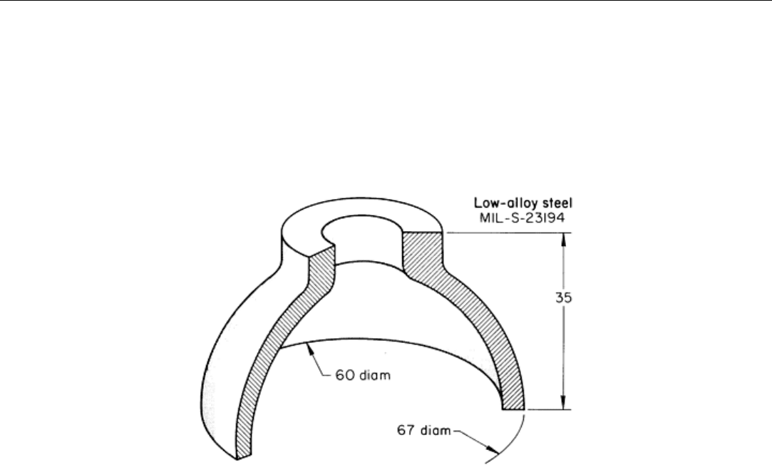
Fig. 20 Symmetrical, dome-
shaped forging that was ultrasonically inspected by the longitudinal wave technique
on
the inside and outside of the dome and on the ends, and by the circumferential shear technique on the
outside of the dome and the neck portion. Dimensions given in inches
The forging illustrated in Fig. 20 was inspected by using the longitudinal wave technique on the inside diameter, outside
diameter, and ends of the forging, plus the circumferential shear technique on the outside diameter. In addition,
circumferential shear was conducted on the outside diameter of the neck portion of the forging.
The landing-gear forging illustrated in Fig. 21 has a more intricate shape and is large, which makes it more difficult to
inspect. For forgings such as this, the best procedure is thorough inspection of the billets prior to forging. A common
practice is to ultrasonically inspect the billet material to an agreed-on specification. This minimizes the amount of
inspection required after forging. A forging such as the one shown in Fig. 21 would be ultrasonically inspected by
immersion, longitudinal wave, hand-scan techniques in all areas where the shape permits. The following examples
describe procedures used for the ultrasonic inspection of a variety of steel and aluminum alloy forgings.
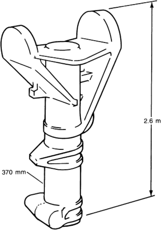
Fig. 21 Landing-gear forging typical of complex forg
ings that are preferably ultrasonically inspected in billet
form because the intricate forged shape prevents thorough ultrasonic inspection
Example 7: Ultrasonic Inspection of Forged Medium-Carbon Steel Axle Shafts
for the Detection of Chevrons and Burning.
Automotive rear-axle shafts (Fig. 22) are made from medium-carbon steels by first forging in closed dies to form the hub
end and then by cold extrusion to form the shaft section. Cold-extruded rear-axle drive shafts are prone to develop serious
internal flaws known as chevrons or cup-cone ruptures. Chevrons are internal ruptures that may or may not extend to the
surface of the extruded stock (most often they do not extend to the surface). There may be any number of chevrons
produced during the extrusion of a single axle shaft. Therefore, it is necessary to inspect the entire length of each shaft.
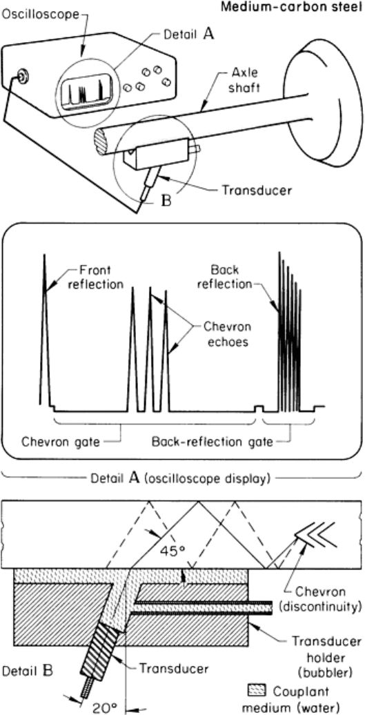
Fig. 22 Setup and operating essentials for the ultrasonic inspection of the shaft portion of a forged medium-
carbon steel axle shaft
Inspection Procedure. To perform a 100% ultrasonic inspection of these axle shafts in a plant where production was
2 to 3 million units annually, an automated system was used. The test station was supplied by a conveyor.
Figure 22 illustrates the position of the axle shaft when the ultrasonic test was performed. A transducer holder, with a
fixed angle fabricated of hardened tool steel with no adjustment, coupled the ultrasound from the transducer to the shaft
end. A detailed view of the transducer holder and V-block is shown in detail B in Fig. 22. Transducers with a frequency
of 1.6 to 2.25 MHz were used to perform the ultrasonic inspection. The transducer incident angle was approximately 20°,
which yielded a 45° shear wave generated within the shaft. This permitted the detection of internal flaws. The
oscilloscope display in detail A in Fig. 22 illustrates the interaction of an ultrasonic beam with a chevron. Two electronic
gates were utilized to monitor two separate areas of the shaft, the area from where the sound enters the shaft to
approximately 150 mm (6 in.) from the end of the flange. This was a positive gate, commonly called the chevron channel.
The second gate was positioned to monitor the back-reflection signal and was a negative gate.
The acceptance of any axle shaft required a strong back reflection with no signal in the chevron channel gate. In addition
to detecting chevrons, this inspection procedure detected the results of any burning that had occurred during heating. A
burned forging attenuated the back reflection and caused the forging to be rejected.
Example 8: Ultrasonic Inspection of a 1.7 m (68 in.) Diam 8822 Steel Billet and
the Ring Into Which It Was Rolled.
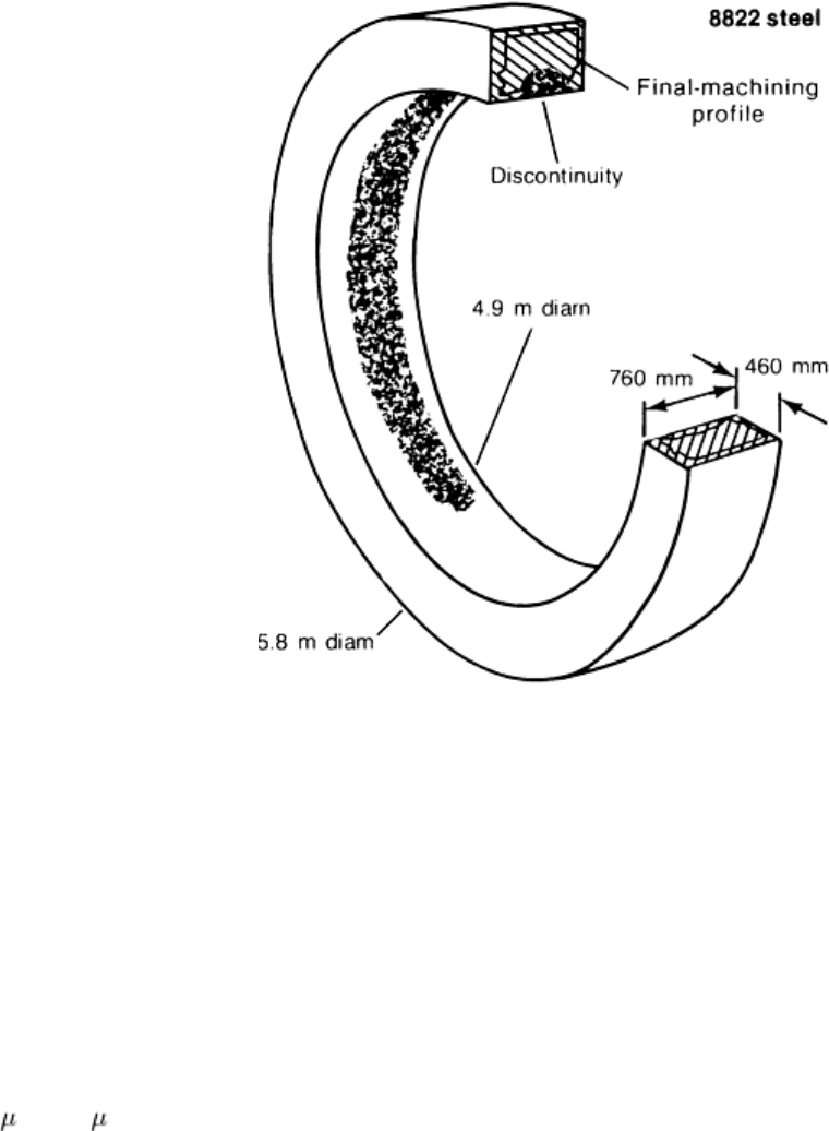
The large steel ring shown in Fig. 23 was produced for a nuclear application from a 1.7 in (68 in.) diam billet of 8822
steel. The large billet was first forged into a doughnut preform in a large press, then formed into the ring by ring rolling.
Fig. 23 Large rolled ring that was ultrasonically inspected as a 1.7 m (68 in.) diam billet and as a rolled ring
A ring of this type requires a high degree of integrity; therefore, inspections were performed at various stages of
manufacture. Routine ultrasonic inspection of the billet revealed a gross center condition in approximately 67% of the
length. Inspection was performed from the outside diameter and end faces to the maximum extent possible. On billets of
this size, however, the surface condition and the lack of refinement of the internal structure have an adverse effect on the
ability to perform a thorough inspection by ultrasonics.
When the billet was preformed into the doughnut shape, the portion that had been the center of the billet was removed.
The doughnut was then ring rolled into a large ring having a wall 460 mm (18 in.) thick (Fig. 23). It was hoped that the
area indicated as defective in the billet stage would have been removed, but because it was uncertain whether all of the
defective area had been removed, the ring was machined on the outside diameter and on one end face to a surface finish
of 6 m (250 in.), thus permitting a more sensitive inspection.
Primary consideration was given to performing a straight-beam ultrasonic inspection from the outside surface in the radial
direction. During ring rolling, included foreign materials become aligned in the circumferential direction to provide a
lamellar-type discontinuity. This type of discontinuity is most readily detected from the perpendicular direction or, in this
case, either from the outside or inside surfaces of the ring. Because the original discontinuities in the billet were in the
center and would remain in a similar position during forging, it was anticipated that if remnants of the center condition
were still present, they would be near or adjacent to the inside or bore of the ring. Therefore, a radial ultrasonic inspection
from the outside using the straight-beam technique was considered to be the best method of detection.
Inspection Procedure. A straight-beam inspection was instituted as indicated, and calibration was established using
the back-surface-reflection method to determine whether adequate ultrasonic penetration was available. A 25 mm (1 in.)
diam, 2.25-MHz transducer was used in conjunction with the ultrasonic unit.
The outside surface was scanned in overlapping paths to ensure complete coverage. During the inspection, areas of
indications were noted at approximately midheight and adjacent to the bore area; one area approximately 7 m (24 ft) long
in a circumferential direction was encountered during the inspection; several smaller spot-type areas were also noted.
Evaluation of indications on the basis of applicable American Society of Mechanical Engineers (ASME) Boiler and
Pressure Vessel Codes revealed that the indications would be acceptable. However, for closer evaluation, a straight-beam
inspection from the face and a circumferential angle-beam inspection, in two 180° opposing directions, were performed.
Straight-beam inspection from the face did not reveal indications at a normal gain or sensitivity level; they could be
detected only at an extremely high sensitivity level. Angle-beam inspections showed very small low-level (approximately
10% maximum) occasional indications in the area previously noted.
Although not required by the ASME code, an axial angle-beam inspection from the outside was performed, mainly in the
area of indications. Indications were readily detectable, but were not considered serious enough to reject the forging. On
the basis of results of the ultrasonic inspections, the ring was considered acceptable within the required specifications.
Magnetic particle inspection revealed a few small indications in the areas tested. Because severity did not appear to be
indicative of the ultrasonic results, the area was conditioned by grinding and polishing to obtain an additional inspection
at a greater depth from the inside surface. Subsequent magnetic particle inspection indicated a much more severe
condition, which was not acceptable.
Conclusions. Metallographic investigation showed that the indications could be classified as areas of chemical
segregation and nonmetallic inclusions (predominantly sulfides). These were evidently present in the center of the billet
and remained in the final ring. Therefore, the ring was considered unsatisfactory for the application. Removal of the
questionable metal and repair by welding was considered, but the cost would have been excessive. Replacement of the
defective ring from an acceptable billet was the most economical solution.
Example 9: Ultrasonic Inspection of a 4340 Steel Shaft Forging.
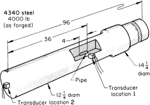
The pulse-echo technique of ultrasonic inspection was selected for locating flakes, bursts, and pipe in large 4340 steel
shaft forgings such as the one shown in Fig. 24.
Fig. 24 Transducer loca
tions for radial and longitudinal ultrasonic inspection of a large steel shaft forging for

detection of flakes, bursts, and pipe. Dimensions given in inches
Equipment Specified. The ultrasonic instrument specified was a pulsed, reflection-type unit capable of testing at 1 to
5 MHz. It was also required that the instrument provide linear presentation (within ±5%) for at least 75% of the screen
height (sweep line to top of screen). It was further specified that the electronic apparatus contain a signal attenuator
(accurate over its useful range to ±10% of the nominal attenuation ratio), which allows measurement of signals beyond
the linear range of the instrument. Transducers 25 to 28 mm (1 to 1 in.) in diameter or 25 mm (1 in.) square were used.
Couplants having good wetting characteristics, such as SAE No. 20 or No. 30 motor oil, glycerin, pine oil, water, or a
nonionic water-soluble polymer, were specified. (The above couplants, however, may not be comparable to one another,
and the same couplant must be used for calibration and recording of results.) Test blocks containing flat-bottom holes
were used for calibrating equipment in accordance with the above apparatus requirements. Such test blocks were used to
establish recording levels for longitudinal testing.
Surface Preparation. It was required that all surfaces be machined so that surface roughness did not exceed 6 m
(250 n.) and that surfaces contacted by transducers should be free from all extraneous material, such as scale, dirt, and
paint, before the couplant was applied.
Inspection Procedure. Ultrasonic inspection was performed after heat treatment, but prior to drilling holes, cutting
keyways, or otherwise machining to a contour. The entire forging was inspected using a test frequency of 2.25 MHz.
Search patterns that incorporated 15% overlap between passes were scanned at a speed of less than 150 mm/s (6 in./s).
Scanning from two mutually perpendicular directions (radial and longitudinal) provided complete coverage. Referring to
Fig. 24, when indications were found with the transducer oriented for radial scanning (transducer location 1), the operator
moved the transducer to location 2, on the end of the forging, to determine the size and axial location of the flaw. In the
forging shown in Fig. 24, pipe that was 100 mm (4 in.) long by 25 mm (1 in.) thick was found in the center of the cross
section and 915 mm (36 in.) from one end of the forging.
Acceptance Standards. Forgings showing a single flaw indication greater than that from a 13 mm ( in.) diam flat-
bottom hole were not acceptable. Forgings containing clustered or traveling indications greater than 50% of that from a 13
mm ( in.) diam flat-bottom hole were not acceptable. Forgings containing a complete loss of back reflection not
attributable to size, shape, or grain size were not acceptable; loss of back reflection not accompanied by an indication
from a flaw was further investigated by the use of other search units. Complete loss of back reflection was assumed when
the back reflection fell to less than 5% of the reference back reflection.
Example 10: Ultrasonic Inspection of an Upset-Forged 4118 Steel Shaft.
Field failures were encountered in the upset portion of forged 4118 steel shafts (Fig. 25). The failures were traced to
internal cracks in the upset flange area that were initiated from gross nonmetallics. These nonmetallics, which were
originally located near the center of the cross section, were pushed outward into an almost radial plane in the upsetting of
the flange. When the shaft was heat treated, these planes of inclusions developed internal cracks.
