ASM Metals HandBook Vol. 14 - Forming and Forging
Подождите немного. Документ загружается.

If the recess is fairly small and far enough from the edges of the blank so that there is a large resistance to metal flow, the
metal can be overstressed at the punch nose and can fracture or tear. To prevent tearing, blankholder pressure is kept as
low as possible to allow almost unrestricted metal flow, but this may produce wrinkles radiating from the lip of the recess.
These wrinkles can be removed by stretching the sidewalls of the recess in a second forming operation.
Large cup-shaped parts that must be stronger in the bottom surface than in the wall are often designed with tapered
wall sections. A tapered section can be made by machining the part before or after drawing.
High-strength low-carbon steels of thinner gage than conventional low-carbon steels can be used without tapering, but
they are more difficult to draw and are more expensive. The use of a tapered blank for a cup-shaped part is described in
the following example.
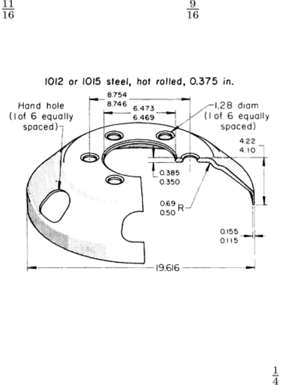
Example 4: Forming a Large Disk From a Tapered Circular Blank.
The truck-wheel disk illustrated in Fig. 4 was formed from a blank 610 mm (24 in.) in diameter that had been roller
tapered from a 500 mm (19 in.) diam blank with a 90.5 mm (3 in.) diam center hole. Taper was about 0.04
mm/mm (0.04 in./in.) of radius. The material was annealed hot-rolled 1012 or 1015 steel, 9.52 mm (0.375 in.) thick,
abrasive blasted to removed scale and oxide.
Fig. 4 Truck-wheel disk that was formed from a tapered blank. Dimensions given in inches.
The blanks were tapered back to back, two at a time, giving each disk only one rolled surface. The tapering rolls were
stopped before reaching the edge of the blank in order to maintain an even taper. Otherwise, lack of resisting stock at the
edge would have caused a torn edge. Tapering started at a diameter of 260 mm (10 in.), just beyond the circle
describing the outer edges of the six round holes; this gave a stock thickness of 8.38 mm (0.330 in.) at the 17.5/12.7 mm
(0.69/0.50 in.) radius.
The combined forming and trimming operation was done in a 13.3 MN (1500 tonf) hydraulic press with the rolled surface
of the work face down in the die. The blank was trimmed to 584 mm (23 in.) in diameter in a compound blank-and-draw
die at a rate of 375 per hour. The die was made of O1 tool steel and was reworked after making 40,000 pieces.
A second operation sized the 498.2 mm (19.616 in.) outside diameter, enlarged the center hole to 164.4 ± 0.05 mm (6.471
± 0.002 in.) in diameter, and pierced six 32.5 mm (1.28 in.) diam holes, using a 7.1 MN (800 tonf) mechanical press. In
the third operation, six hand holes were punched, one at a time. To attach a rim to a disk, 16 rivet holes evenly spaced
around the circumference of the flange were pierced in both the disk and the rim at the same time.
The optional 1015 steel had the highest carbon content that could be used in this part. Work hardening increased its
strength and hardness. If the hardness of the workpieces exceeded 91 HRB, hairline cracks radiated from the rivet holes,
causing rejection, as observed when 1020 steel was used.
Localized severe forming is encountered in making many large irregular shapes by press forming. This imposes
stringent demands on process planning; quality of work metal; lubrication; and the design, material, and maintenance of
dies--as demonstrated in the following example.
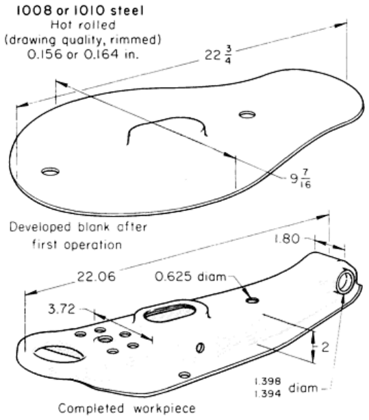
Example 5: Severe Embossing and Hole Flanging in Press Forming a Control
Arm.
The severe embossing and hole flanging demanded on the automobile control arm shown in Fig. 5 required the use of
drawing-quality steel for the workpiece and high-quality tool steel for the dies, close attention to tool maintenance, and
the use of a heavy-duty lubricant. The stock was hot-rolled drawing-quality rimmed 1008 or 1010 steel, pickled and oiled,
with a hardness of 55 HRB. Commercial-quality steel had been tried, but was unsatisfactory for the severe forming. Stock
thickness was 3.96 or 4.17 mm (0.156 or 0.164 in.). Wall thickness of the hole flanges had to be at least 2.67 mm (0.105
in.), and flange width was 7.62 mm (0.30 in.). The parts were formed with dies of hardened W2 tool steel. A developed
blank was used, making a final trimming operation unnecessary. The operations were as follows:
• Blank to developed outline, pierce two locating holes, form center boss--done in a 1.8 MN (2
00 tonf)
mechanical press with W2 tool steel die inserts hardened to 57 to 60 HRC
• Form in a 5.3 MN (600 tonf) mechanical press using W2 tool steel dies hardened to 61 to 64 HRC
• Pierce two holes in flanges, enlarge one locating hole, pierce oval hole in center boss--
done in a 620 kN
(70 tonf) inclined-bed mechanical press
•
Restrike to size and sharpen radii, form dimple, flange round hole and oval hole in a 5.3 MN (600 tonf)
mechanical press
• Pierce remaining holes in a 620 kN (70 tonf) inclined-bed mechanical press
•
Outward flange two side holes to 35.5/35.4 mm (1.398/1.394 in.) in diameter, 2.67 mm (0.105 in.)
minimum wall thickness, and 7.62 mm (0.30 in.) minimum flange height, using hydraulic equipment
designed for this part
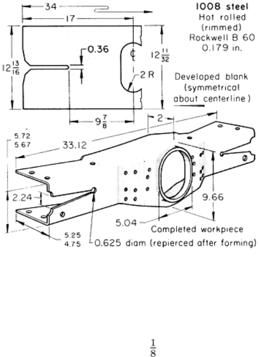
Fig. 5 Press-formed control arm on which embossing and hole flanging were of near-
maximum severity.
Dimensions given in inches.
A dry-film lubricant consisting of soap and borax was applied to the blank. Where further lubrication was needed, an oil-
base compound was added. Production rate ranged from 200 to 325 pieces per hour, production-lot size was 10,000
pieces, and annual demand was more than 200,000 pieces. Except for minor repairs, the dies were good for one year of
production.
Blanks That Cannot Be Nested. Irregularly shaped parts frequently must be made from developed blanks with a
contour that makes close nesting of the blanks impossible. Channel-shaped parts with flanges or web of varying width use
blanks that are cut with more scrap than parts with flanges or web of unvarying width, and an excessive amount of scrap
may be generated in producing them.
In some applications, material that would otherwise be wasted can be moved into a useful location after notching or
lancing. This was done in the following example, in which the web was notched at the end and then spread into a V-shape
to increase flange height at the ends and to reduce blanking scrap.
Example 6: Use of a Notched Blank to Increase Flange Width and Reduce Scrap
in Forming an Irregular Channel-Shaped Part.
A flange of varying width was needed on the channel-shaped truck-frame member shown in Fig. 6. Instead of using a
contoured blank, which would have meant considerable waste in blanking, the additional flange width was gained by
notching each end of a nearly rectangular blank and spreading the notch into a V-shape during the forming operation. The
end of each notch was radiused to minimize cracking during forming. The stock saved by notching the blank was 1.4 kg
(3 lb) per piece.
Fig. 6 Press-formed truck-
frame member that was notched and spread to increase flange width locally and
therefore save material in blanking. Dimensions given in inches.
The workpiece was made of 4.54 mm (0.179 in.) thick hot-rolled, rimmed 1008 steel, pickled and oiled. Each of the two
notches in the blank was 9.1 mm (0.36 in.) wide by 181 mm (7 in.) long. The notches were spread to make V-shape

openings 56.9 mm (2.24 in.) wide at the ends. Flange widths varied from 50 mm (2 in.) at the center of the part to 127
mm (5 in.) at each end of the channel. The operations were:
• Cut blank to developed outline, and pierce large center hole (Fig. 6). A 3.1 MN (350 t
onf) mechanical
press with a mechanical unloader produced 300 to 400 blanks per hour
• Form completely, including flange around center hole, in a 16 MN (1800 tonf) hydraulic press
• Pierce all holes in the web, and trim 18.8 mm (0.74 in.) radius at two place
s on each end in a 2.9 MN
(325 tonf) mechanical press
• Pierce holes in top and bottom flanges, and restrike flange ends in a 2.9 MN (325 tonf) mechanical press
Presses for the second, third, and fourth operations listed above, operating at 250 to 310 strokes per hour, were set up in a
line with transfer equipment between them. In the second operation, a spreader was incorporated into the die to assist in
opening the notch to a V-shape. The 181 mm (7 in.) length of the notch had been carefully developed so that the notch
would spread to the required maximum width without causing the work metal to split. After forming, a 15.87 mm (0.625
in.) diam hole was pierced at the end of each notch to remove any fractured material or other stress raisers aggravated by
the severe edge forming.
The forming punches were made of 1045 steel. The wear surfaces on the punch and die were W2 tool steel hardened to 61
to 64 HRC. As a lubricant, a soap solution was dried on the stock. Some heats of steel were difficult to form; for these, an
oil-base compound was used as additional lubricant.
The truck-frame member was made in lots of 27,000 pieces for an annual production of 270,000 pieces. Except for minor
repairs, such as replacing small punches, the dies were good for 1 year of production.
Use of Draw Beads. A draw bead in a blankholder controls the movement of metal into the cavity by providing
additional resistance to metal flow. The location of the beads is usually determined in die tryout; dies for producing
similar parts can be used as a guide.
A single bead is generally placed around the cavity, and additional beads are placed in areas where more control is
needed. Conditions may indicate that the bead size should be reduced or that the whole bead omitted in some places.
Short beads can be placed at an angle to deflect metal into or away from local areas.
Whether the bead is placed in the draw ring or in the blankholder is determined by the die construction. Placing the
groove in the upper member has the advantage that it will not catch dirt. However, the groove should be put in the
member that is to be altered during spotting for mating of opposing surfaces. For convenience in making alterations, this
is usually the lower member.
Unless they are part of the product design, draw beads are placed outside the trim line, as shown in Fig. 7(a). The trim line
can be on the punch or the blankholder. A locking draw bead, such as that shown in Fig. 7(b), is used to provide
maximum restriction to metal flow. Locking beads are used when forming to shape is done primarily by stretching the
metal under the punch, rather than by moving metal into the cavity.
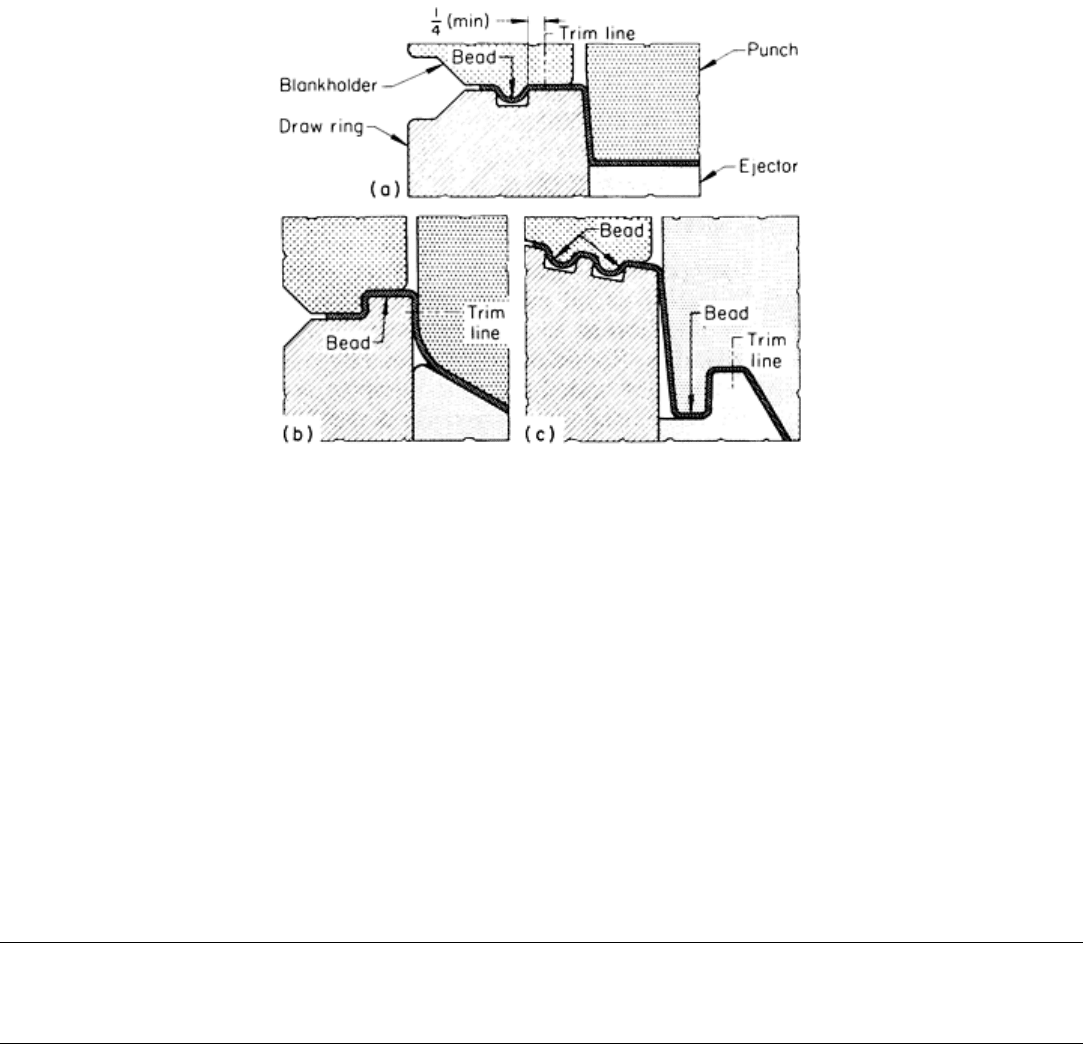
Fig. 7 Use of draw beads. (a) Conventional. (b) Locking. (c) Combined conventional and locking.
Dimensions
given in inches.
Figure 7(c) shows the use of conventional and locking beads. Here, conventional beads control metal flow into the die
cavity until the last portion of the punch movement, when the locking bead gradually engages the metal to restrict its
flow. The last fraction of a millimeter of punch travel causes stretch in the metal under the punch.
Beads in the concave surfaces of a blankholder are usually 3 mm (0.12 in.) deeper than beads on the top or straight
surfaces. This eliminates locking on the top surfaces during preforming of the blank to the shape of the concave
blankholder surface.
Sometimes, draw beads need not be used for the full depth of draw, or need to be used only in certain locations, such as
the corners of regular or irregular polygon-shaped parts. In such cases, some of the material may be allowed to slip
through the draw bead to be retained at the end of the stroke only by blankholder pressure. More information on the
design and construction of draw beads is available in the article "Deep Drawing" in this Volume.
Press Forming of Low-Carbon Steel
Revised by John Siekirk, General Motors Technical Center
Forming of Ribs, Beads, and Bosses
Unsupported sheet metal surfaces that might buckle or oil can are often stiffened by the addition of long, thin bosses
called beads or ribs. Round or nearly round bosses are sometimes called buttons. Dimples are occasionally used as a
recess for a rivet or screw head. The forming of ribs, beads, and bosses is a combination of bending, stretching, and
drawing and involves high shear forces.
Design of Bosses. Bosses are usually about one stock thickness in depth. The radius of curvature on the inside of
bends is about one stock thickness. A typical bend appears to be about four stock thicknesses wide on the convex side and
about three stock thicknesses wide on the concave side. Some recesses for screw heads have sloping sides with very little
curvature.
Bosses are typically produced at the same time that other forming operations are done and in the same dies, although they
can be formed at separate stations in a progressive die. Die clearances can be critical in the forming of decorative bosses
and embossed lettering, especially when definition must be sharp and detail must be accurate. On the other hand,
reinforcing beads usually do not require great accuracy and can be produced in dies with the clearances typical of
ordinary forming.
Use of Bosses. Bosses are often used to provide flatness, stiffness, and reinforcement to formed parts. They can also
serve as locators for subsequent operations. In Example 5 in this article, an oval boss was used as a hole-locating surface
and as the hole flange. The most frequent use of embossed beads is to lighten the weight of products by making it possible
to use thinner metal than would be feasible without bosses, as described in the following example.
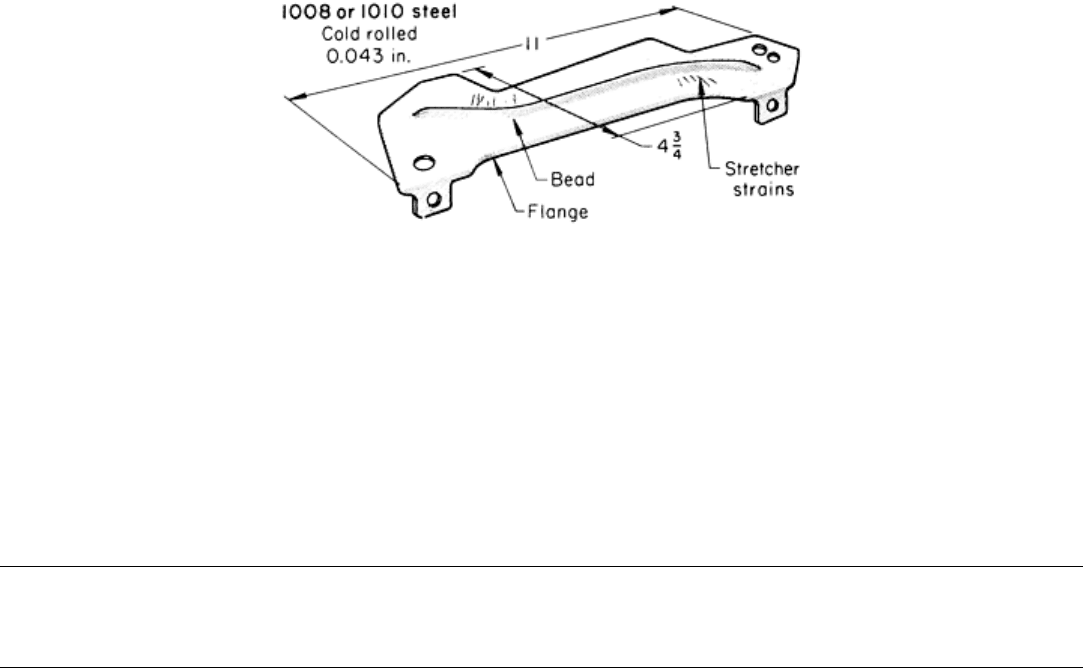
Example 7: Use of a Bead for Stiffening a Corner Bracket.
The corner bracket shown in Fig. 8 had a bead on the flat surface to produce stiffness. The work material was 1.09 mm
(0.043 in.) thick cold-rolled 1008 or 1010 steel. The bead made the use of heavier stock unnecessary. A short flange
around the periphery of the bracket also added to the stiffness.
Fig. 8 Corner bracket that was stiffened by beading and flanging. Dimensions given in inches.
The bracket was produced in a progressive die in the following operations: trim to shape, pierce, form bead, form flange,
and pinch trim from the carrier strip. The die was run in a 4.45 MN (500 tonf) press operating at 600 strokes per hour.
Forming of the bead caused some distortion of the pilot holes and resulted in stretcher strains that extended from the
inside radius of the bead to the edge.
The progressive die was made of D2 tool steel hardened to 62 to 64 HRC. One hour per week was needed to clean the die
and to make minor repairs. Die lubricant was chlorinated oil.
Press Forming of Low-Carbon Steel
Revised by John Siekirk, General Motors Technical Center
Accuracy
Tolerances that can be maintained in the press forming of steel depend on press condition, accuracy of the tools,
workpiece shape, and hardness and variation in the thickness of the work metal.
Flange Width. In forming 90° flanges, if the break lines in the plan view and side elevation are straight or nearly
straight, there should be no difficulty in holding a tolerance of ±0.76 mm (±0.030 in.) on flange width. When flange break
lines are curved significantly, tolerance usually must be increased to ±1.52 mm (±0.060 in.).
The overall length and width of large formed parts such as automobile hoods and deck lids can usually be held to a
tolerance of ±0.76 mm (±0.030 in.). For small formed parts, closer tolerances can be met in production.
Bend Angle. Tolerances that can be held on bend angles depend greatly on the thickness and hardness of the work metal
and on the flange height, because these factors affect springback. A 90° bend in low-carbon steel will spring back about
3°; therefore, either the dies are built to overform by this amount or the bend region is compressed to set the corner. To
provide enough metal for gripping in the die, the minimum inside flange height should be 2 times the stock thickness,
plus the bend radius.
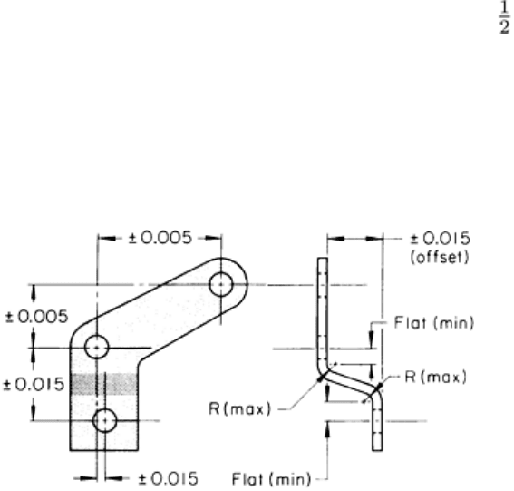
Distance Between Holes. Distances between the centerlines of pierced holes that lie in a common surface of a formed
part are commonly held within a total tolerance of 0.25 mm (0.010 in.) or less (see the article "Piercing of Low-Carbon
Steel" in this Volume). The relation of hole positions in parallel or in-line surfaces of formed parts can be held to ±0.38
mm (±0.015 in.); holes with a smaller tolerance on the centerline distance should be pierced after forming (Fig. 9).
Fig. 9
Tolerances on hole position and distance between offset parallel surfaces on formed parts, and
recommended dimensions to be specified for formed offsets. The tolerances shown apply to holes pierced
before forming; holes in
offset parallel surfaces with position tolerances less than ±0.38 mm (±0.015 in.)
should be pierced after forming. Dimensions given in inches.
Distance Between Offset Surfaces. In ordinary commercial practice, the distance between two offset flat surfaces
in parallel planes can be maintained within ±0.38 mm (±0.015 in.). For closer tolerances, extreme accuracy must be built
into the tools, and the stock thickness must be held closer than normal mill tolerances. The following example describes
the techniques used to maintain a tolerance of ±0.25 mm (±0.010 in.) on the distance between surfaces.
Example 8: Variation of a Critical Distance Between Offset Parallel Planes.
On the brake-assembly backing plate shown in Fig. 10, the distance between the tops of the six pads (A to F, Fig. 10) and
the bottom of the center mounting face had to be within ±0.25 mm (±0.010 in.). The ranges of dimensions for all six pads
as measured on 22 pieces are plotted in the graph in Fig. 10. Of the 132 individual measurements, only 7 exceeded the
limits. The spread in dimensions was the result of a combination of variables, including stock thickness (±0.18 mm, or
±0.007 in.), springback after forming and coining, and condition of the press.
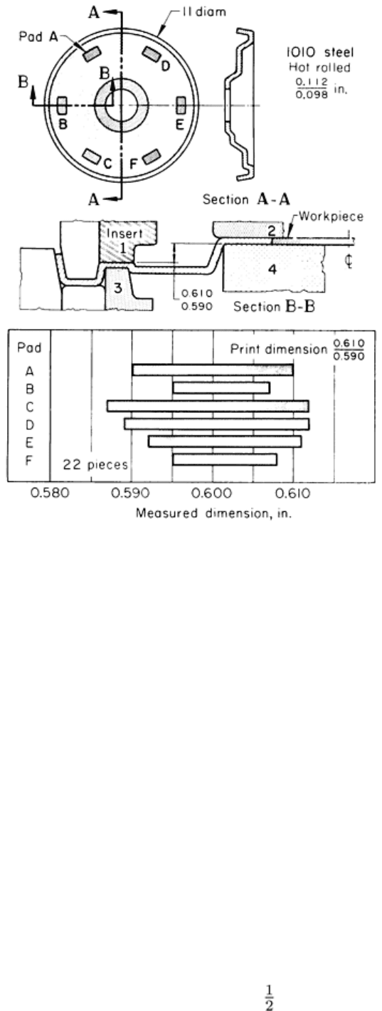
Fig. 10 Variation of offset distance in a formed and coined backing plate for a broke assembly.
Dimensions
given in inches.
Springback was unpredictable and varied among different lots of steel. Therefore, the die was made extra rigid, and the
inserts for coining the pads (inserts 1 and 3, section B-B, Fig. 10) were made adjustable to compensate for variations in
stock thickness. Coining reduced stock thickness at the 1600 mm
2
(2.5 in.
2
) pads to 2 to 2.3 mm (0.080 to 0.090 in.)--a
15% reduction.
The backing plate was made in two operations, both in a 7.1 MN (800-tonf) mechanical knuckle press with a 127 mm (5
in.) stroke, which was operated at 20 strokes per minute. In the first operation, coil stock was fed into a progressive die,
where the inner portions of the part were formed, the six pads were partly completed, the center hole was pierced, and the
outside diameter was blanked. The outside flange was formed, and the six pads were coined to height and parallelism in a
second die (section B-B, Fig. 10).
The press slide was parallel to the bolster within 0.25 mm/m (0.003 in./ft). The slide and the press bed were large enough
to keep the die set centered, thus minimizing the possibility of error. The die set had four heavy guideposts in long
bushings. The main parts of the punch and die were made of 6145 steel hardened to 45 to 50 HRC and ground after
hardening, and the inserts for coining (inserts 1 through 4, section B-B, Fig. 10) were made of O1 tool steel hardened to
60 to 61 HRC and ground.
Holes Close to a Bend. Whether a hole that is close to a bend is pierced before or after forming depends on the
function of the hole, its closeness to the bend, the bend radius, and the stock thickness. When the distance from the edge
of the hole to the inside surface of the other leg of the bend is less than 1 times the stock thickness, plus the bend radius,
the outer portion of the hole is likely to deform as a result of stretching of the metal. If the deformation is acceptable, the
hole can be pierced before forming; otherwise, it must be pierced after forming. When the offset angle on formed parts is
unimportant, stating the minimum flat and maximum radius dimensions as in Fig. 9 allows the maximum practical
tolerance in producing acceptable parts.
Trimmed edges can be held to close tolerances when they are trimmed by one punch and when trimming is done after
any forming that would cause distortion, as in the following example.
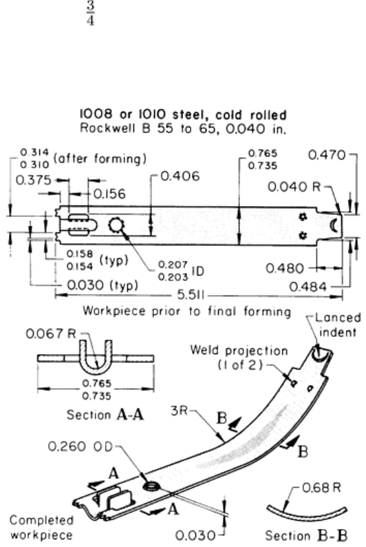
Example 9: Forming and Accurate Trimming in a Progressive Die.
Figure 11 shows an eggbeater side frame that was produced in a four-station progressive die from 1 mm (0.040 in.) thick
cold-rolled 1008 to 1010 steel strip 19 mm ( in.) wide. For accurate fit in assembly, the end of the part was trimmed to
the close tolerances indicated in Fig. 11 after the U-shaped bead flanked by the vertical tabs had been formed. The bead
was formed by drawing metal from the surrounding area and by stretching.
Fig. 11 Eggbeater side frame that was formed and accurately trimmed in a progressive die.
Dimensions given
in inches.
The stock had a No. 6 edge, a No. 3 finish, and a hardness of 55 to 65 HRB. The No. 6 edge (a square edge produced by
edge rolling the natural edge of hot-rolled strip or slit-edge strip) was relatively burr free. Because the edges of the strip
were also the edges of the completed part, the use of a No. 6 edge eliminated a deburring operation. The No. 3 finish was
particularly suited to bright nickel plating without prior polishing or buffing. Stock was purchased to average in the lower
part of the standard thickness range of ±0.05 mm (±0.002 in.) and within the standard width tolerance of ±0.38 mm
(±0.015 in.). The sequence of operations in the four die stations was as follows:
• Lance and form semicircular indent, and notch-trim
• Pierce rectangular slot at one end, pierce round hole, and emboss weld projections
• Lance tabs, form bead and form flange around round hole
• Cut off (trim) and form contour
The die, made of D2 tool steel, was used in a 665 kN (75 tonf) press; die life between regrinds was 65,000 pieces. Mineral
oil was used as the lubricant. The production rate was 360 pieces per hour; annual production quantity was 600,000
pieces.
Close Tolerances. Closer-than-conventional accuracy can be attained in sheet metal parts with accurate dies, precise
location of the parts in the dies, and handling equipment designed to avoid damage to semifinished or finished
workpieces. Press condition is also an important factor. The following example describes the techniques used for close-
tolerance forming in progressive dies.
Example 10: Use of Progressive Die to Meet Close Tolerances on a Lamp
Bracket.
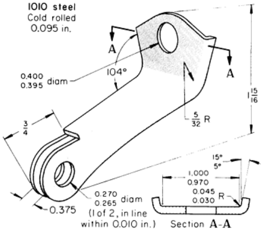
The lamp bracket shown in Fig. 12 had several tolerances that were closer than normal. Three holes had to be pierced to a
tolerance of +0.13, -0 mm (+0.005, -0 in.) on diameter, and two of the holes had to be in line within 0.25 mm (0.010 in.)
after forming. In addition, when the 104° bend was made with the preformed flanges out, the radius of bend on the
flanges had to be held within 0.38 mm (0.015 in.) total indicator reading, and the 10° angle of the flanges had to be held
within ±5°. The bracket was produced in a seven-station progressive die with two piloting stations that could have been
used for auxiliary operations such as shaving or restriking, if necessary. The operations were as follows:
• Notch for stop, pierce one 10 mm (0.395 in.) hole, pierce two 6.7 mm (0.265 in.) holes
• Blank the contour of the ears
• Pilot
• Blank the partial contour
• Form the two long flanges
• Pilot
• Form the 104° angle and cut off
Fig. 12 Lamp bracket that was press formed to close tolerances in a progressive die. Dim
ensions given in
inches.