API Std 618-2007 Reciprocating Compressors for Petroleum, Chemical, and Gas Industry Services
Подождите немного. Документ загружается.

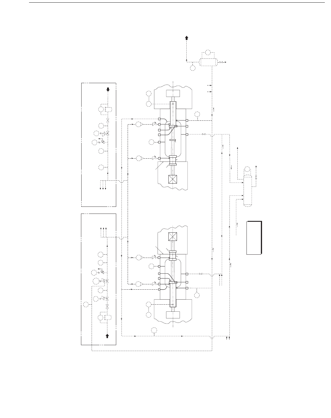
Figure I-1—Typical Buffered Single Compartment Distance Piece Vent, Drain, and Buffer Arrangement to Minimize
Process Gas Leakage
Notes:
1. See 6.12.2 and 6.13.1.6
2. Buer gas pressure must be at least 1 bar (15
pounds per square inch) higher than the
disposal system pressure at connection A or
connection G (in the outboard distance piece)
whichever is higher.
3. The oil wiper packing may
be on the distance
piece side of the partition and integral with the
buer seal packing (1).
4. In some cases, lower buer and vent
pressures than the examples shown in the
packing details may be necessary to
accomodate the pressure limitations
of large
distance pieces.
5. Several other distance piece and packing
arrangements for pressuring, buering,
purging, and venting are possible, and the
arrangement to be used should be agreed upon
between the purchaser and the vendor.
6. Some users may choose to shutdown as
well
as alarm in some cases.
7. Fixed pressure control or dierential pressure
control depending on the variability of the
disposal system.
8. Keep the disposal from the distance piece
liquid collection pot and packing leakage liquid
collection separate. The distance
piece liquid
collection pot should be connected to a vapor
recovery system or a low pressure are system.
The packing leakage liquid collection pot can
be connected to either a vapor recovery, a low
pressure are, or a conventional are
system.
9. To or from other cylinders on the same
machine. When dierent cylinders on a
common frame are in dierent services,
individual isolation of vents and drains may be
required.
Intended Mode of Operation
• The distance piece operates at disposal system pressure-usually a gauge pressure of 0.15 to 0.4 bar (2 to 5
pounds per square inch) and is lled with a mixture of inert buer gas and process gas. The packing vent TI
allows monitoring of
the packing condition. There is normally no process gas leakage into the distance
piece. Under abnormal conditions (such as packing deterioration), the rate of leakage of process gas into
the crosshead guide is dependent on the condition of the pressure packing and the buer seal packing (1).
• Alternati
vely, the disposal system may be operated at a vacuum, at an absolute pressure of 0.7 to 0.9 bar
(10 to 13 pounds per square inch), based on an atmospheric pressure of 1 bar (14.7 pounds per square
inch), in which case the crosshead guide leakage may
be into the distance piece, and a pump could be
needed for the distance piece liquid collection pot drain.
• The liquid collection pots will require occasional draining.
• The distance piece vent header PSH is set to alarm (or shutdown) if the pressure packing on one cylinder
fails.
Legend:
A Vent, distance piece – NPS 1.50
B Purge, buer, or pressure, packing or distance piece – NPS 1.00
C Lube, pressure packing – NPS 1.00
D Drain, distance piece – NPS 1.00
E Coolant out, pressure packing – NPS 1.00
F Coolant in, pressure packing – NPS 1.00
G Common vent and drain, pressure
packing – NPS 1.00
(1) Buer seal packing
(2) Intermediate partition packing
- - - - - - - - - - - Electrical signal
Typically, all components external to distance piece or as shown in
broken line – – – – – are furnished by purchaser.
Note:
This is a typical system and may
require modication based on
specic user requirements
(see I.1).
PI
To disposal system
(e.g. vapor recovery
or low pressure are)
(see note 8)
Oil and condensate
drain
From other
cylinders
(note 9)
Leak os from cylinder and clearance
pocket unloaders. (optional - note 9)
Pressure packing combined vent and drain
Distance piece drain
Monitoring
(note 6)
Nom. 6 BAR
(
100 PSIG)
Buer gas supply
Filter
(note 2)
(note 6)
To other
cylinders
(note 9)
Buer gas (note 2)
Distance piece vent [see I.5(i)]
5-50 SCFH
5-50 SCFH
Monitoring
B
D
B C B
E
F
A
G
Frame end
Crosshead
Crosshead guide
Outboard
distance piece
Access opening
(solid cover)
Oil wiper packing
(see note 3)
Partition
Oil slinger
Piston rod
Pressure
packing
(1)
Piston
Cylinder
TE TI
PRV
PDI
From other
cylinders
(note 9)
From other
cylinders
(note 9)
Slope
Slope
Slope
Slope
PCV
DPCV
PI
PI
PSL
Nom. 6 BAR
(100 PSIG)
Buer gas supply
Filter
(note 2)
(note 6)
To other
cylinders
(note 9)
PRV
PDI
PCV
PIPSL PI
PSH
TI
NO
Distance piece
liquid collection pot
NC
LG
Slope
NO
Monitoring
NC
Slope
TI
PI
Packing leakage
liquid collection pot
To disposal system
(note 8)
Oil and condensate
drain
LG
FI
FI
FOR VARIABLE PRESSURE DISPOSAL SYSTEMS – NOTE 7
FOR CONSTANT PRESSURE DISPOSAL SYSTEMS – NOTE 7
TYPE A DISTANCE PIECE TYPE B DISTANCE PIECE
PI
5-50 SCFH
5-50 SCFH
Monitoring
B
D
BCB
E
F
A
G
Frame end
Crosshead
Crosshead guide
Outboard
distance piece
Access opening
(solid cover)
Oil wiper packing
(see note 3)
Partition
Piston rod
Pressure
packing
(1)
Piston
Cylinder
TETI
FI
FI
PI
RECIPROCATING COMPRESSORS FOR PETROLEUM, CHEMICAL, AND GAS INDUSTRY SERVICES 161
Copyright American Petroleum Institute
Provided by IHS under license with API
Licensee=IHS Employees/1111111001, User=Japan, IHS
Not for Resale, 01/01/2008 21:15:45 MST
No reproduction or networking permitted without license from IHS
--```,`,,,,`,``,,```,`,,`,,,,`-`-`,,`,,`,`,,`---
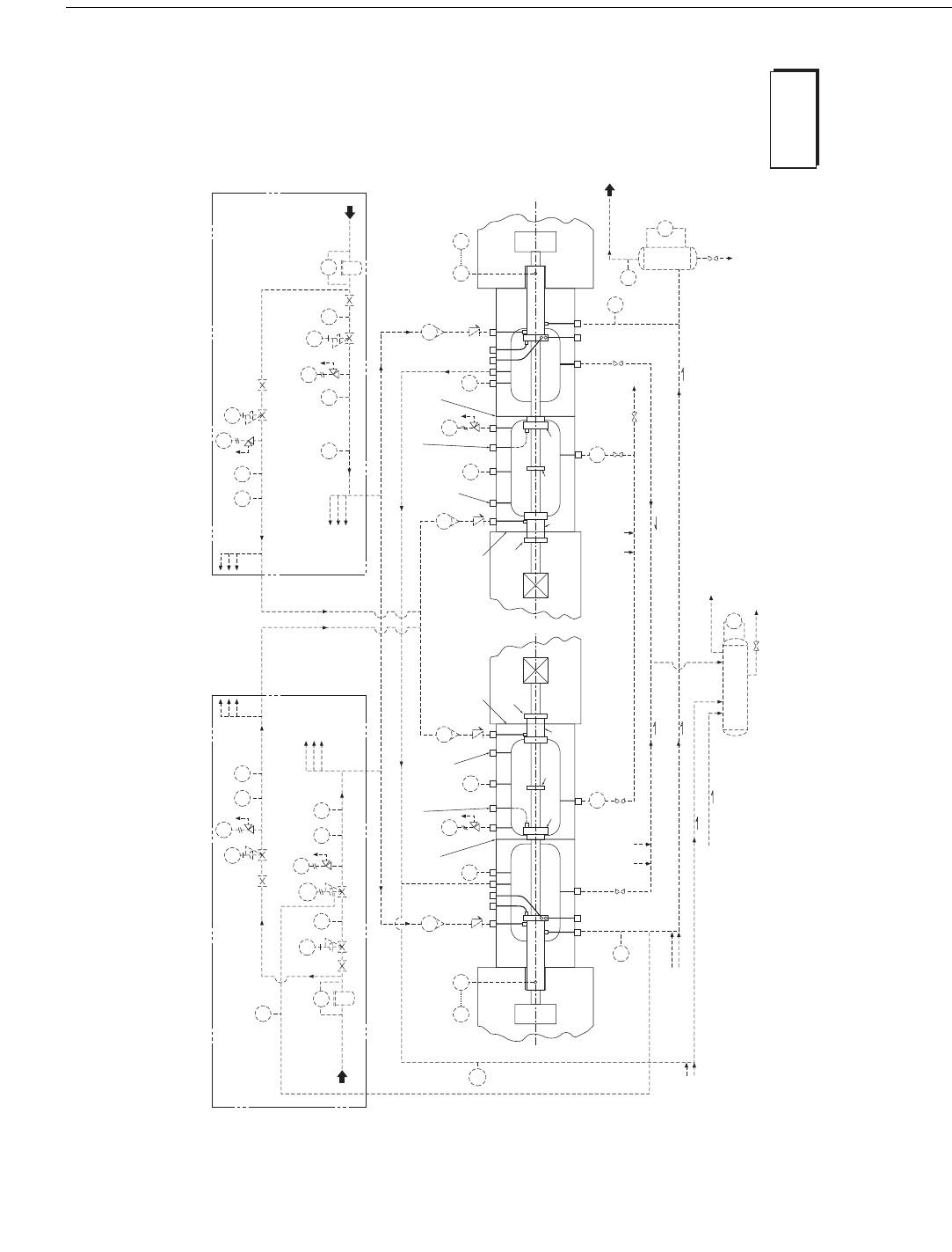
Figure I-2—Typical Buffered Two Compartment Distance Piece Vent, Drain, and Buffer Arrangement to Minimize
Process Gas Leakage
PI
PRV
To disposal system
(e.g. vapor recovery
or low pressure are)
(note 12)
Oil and condensate
drain
From other
cylinders
(note 13)
Leak os from cylinder and clearance
pocket unloaders. (optional - note 13)
Inboard distance piece drain
Outboard distance piece drain
Pressure packing combined vent and drain
(Monitoring)
(note 9)
Nom.
6 BAR
(100 PSIG)
Buer gas supply
Filter
(note 2)
(note 9)
To other
cylinders
(note 13)
(note 9)
Buer gas pressure P
1
(note 2)
Distance piece vent [see I.5 (i)]
Buer gas pressure P
2
(notes 2, 10)
PI
5-50 SCFH
5-50 SCFH
Monitoring
B B B B A
D
D G
B
A
C B
E
F
Frame end
Crosshead
Crosshead guide
Inboard
distance piece
Access opening
(solid cover)
Outboard
distance piece
Access opening
(solid cover)
Oil wiper packing
(note 3)
Partition
Optional inboard
distance piece purge
Intermediate
partition
Optional intermediate partition
packing purge
Oil slinger
Piston rod
Pressure
packing
(1)
(2); (note 4)
Piston
Cylinder
PI
PRV
FI
PI
FI
5-50 SCFH
5-50 SCFH
(Monitoring)
BBBBA
D
DG
BACB
E
F
Frame end
Crosshead
Crosshead guide
Inboard
distance piece
Access opening
(solid cover)
Outboard
distance piece
Access opening
(solid cover)
Oil wiper packing
(note 3)
Partition
Optional inboard
distance piece purge
Intermediate
partition
Optional intermediate partition
packing purge
Oil slinger
Piston rod
Pressure
packing
(1)
(2); (note 4)
Piston
Cylinder
TETI TE TI
PRV
PRV
PDI
FG
FG
From other
cylinders
(note 13)
NC
From other
cylinders
(note 13)
From other
cylinders
(note 13)
Slope
Slope
Slope
Slope
PCV
PCV
DPCV
PI
PSLPI
PI
PSL
Nom. 6 BAR
(100 PSIG)
Buer gas supply
Filter
(note 2)
(note 9)
To other
cylinders
(note 13)
To other cylinders
(note 13)
To other cylinders
(note 13)
(note 9)
PRV
PRV
PDI
PCV
PI
PSL PI
PSL PI
PCV
PSH
TI
NO
Distance piece
liquid collection pot
NC
LG
Slope
NC NO
(Monitoring)
NC
Slope
To
drain
TI
PI
Packing leakage
liquid collection pot
To disposal system
(note 12)
Oil and condensate
drain
LG
FI
FI
Notes:
1. See 6.12.2 and 6.13.1.6
2. Buer gas pressure P
1
must be at
least 1 bar (15 pounds per square
inch) higher than the disposal
system pressure at connection A or
connection G (in the outboard
distance piece) whichever is higher.
Buer gas pressure P
2
must be at
least 1 bar (15 pounds per square
inch) higher than the disposal
system pressure at connection A (in
the outboard distance piece).
3. The oil wiper packing may be on
the distance piece side of the
partition and integral with the
buer seal packing (1).
4. The intermediate partition
packing (2) may be buered in
addition to the pressure packing in
which case the inboard distance
piece may be vented to the
atmosphere.
5. In some cases, lower buer and
vent pressures than the examples
shown may be necessary
to
accomodate the pressure
limitations of large distance pieces.
6. Several other distance piece and
packing arrangements for
pressuring, buering, purging, and
venting are possible, and the
arrangement to be used should be
agreed upon between the
purchaser and the vendor.
7. The
orientation of the distance
piece and packing ange/case
connections may vary depending
on the individual distance piece and
the type of packing case used.
8. The intermediate partition
packing (2) may be located in the
outboard distance piece on the
other side of the partition from that
sho
wn.
9. Some users may choose to
shutdown as well as alarm in some
cases.
10. Buer gas may be fed either to
the buer seal packing (1) as
shown, or directly into the inboard
distance piece.
11. Fixed pressure control or
dierential pressure
control
depending on the variability of the
disposal system.
12. Keep the disposal from the
distance piece liquid collection pot
and packing leakage liquid
collection separate. The distance
piece liquid collection pot should
be connected to a vapor recovery
system or a low pressure are
system. The packing leakage liquid
collection pot can be connected to
either a vapor recovery, a low
pressure are, or a conventional
are system.
13. To or from other cylinders on
the same machine. When dierent
cylinders on a common frame are in
dierent services, individual
isolation of vents and drains may be
required.
Intended Mode of Operation
• The inboard distance piece is full of inert buer gas and will stabilize at a gauge pressure of 0.7 to 1 bar
(10 to 15 pounds per square
inch). Infrequent oil draining is required.
• The outboard distance piece operates at disposal system pressure-usually a gauge pressure of 0.15 to 0.4 bar (2 to 5 pounds per
square inch) and is lled with a mixture of buer gas and
process gas. The packing vent TI allows monitoring of the packing
condition. There is normally no process gas leakage into the distance piece. Under abnormal conditions (such as packing
deterioration), the rate of leakage of process gas into the crosshead guide is dependent on the condition of the pressure packing,
the
intermediate partition packing (2), and the buer seal packing (1).
• Alternatively, the disposal system may be operated at a vacuum, at an absolute pressure of 0.7 to 0.9 bar (10 to 13 pounds per
square inch), based on an atmospheric pressure of 1 bar
(14.7 pounds per square inch), in which case the crosshead guide leakage
may be into the distance piece, and a pump could be needed for the distance piece liquid collection pot drain.
• The liquid collection pots will require occasional draining.
• The distance piece vent header PSH is
set to alarm (or shutdown) if the pressure packing on one cylinder fails.
Legend:
A Vent, distance piece – NPS 1.50
B Purge, buer, or pressure, packing or distance piece – NPS 1.00
C Lube, pressure packing – NPS 1.00
D Drain, distance piece – NPS 1.00
E Coolant out, pressure packing – NPS 1
.00
F Coolant in, pressure packing – NPS 1.00
G Common vent and drain, pressure packing – NPS 1.00
(1) Buer seal packing
(2) Intermediate partition packing
- - - - - - - - - - - Electrical signal
Typically, all components external to distance piece or as shown in broken line – –
– – – are furnished by purchaser.
Note:
This is a typical system and may
require modication based on
specic user requirements
(see I.1).
FOR VARIABLE PRESSURE DISPOSAL SYSTEMS – NOTE 11 FOR CONSTANT PRESSURE DISPOSAL SYSTEMS – NOTE 11
TYPE C DISTANCE PIECE TYPE D DISTANCE PIECE
PI
162 API STANDARD 618
Copyright American Petroleum Institute
Provided by IHS under license with API
Licensee=IHS Employees/1111111001, User=Japan, IHS
Not for Resale, 01/01/2008 21:15:45 MST
No reproduction or networking permitted without license from IHS
--```,`,,,,`,``,,```,`,,`,,,,`-`-`,,`,,`,`,,`---
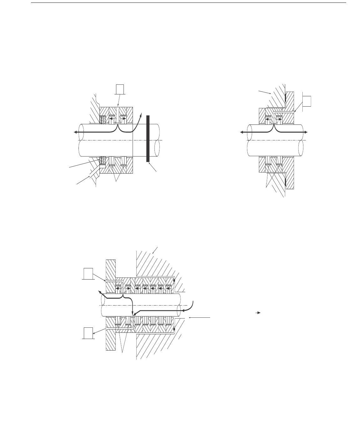
Figure I-3—Typical Purged Packing Arrangements
WTPR (see note 4)
B
G
Buffer gas
(see note 3)
Inert buffer
gas pressure P
1
(see note 2)
Packing vent to disposal
system (flare) maximum
gauge pressure 1.5 bar
(25 psi)
Distance piece side
Cylinder head
Cylinder side
Cylinder
gas pressure
PRESSURE PACKING WITH INERT BUFFER GAS PURGE
Process gas
B
Buffer gas
(see note 3)
Distance piece
intermediate
partition
Inboard
distance piece
WTPR
(see note 4)
Outboard
distance piece
Buffer gas
(see note 3)
Inert buffer
gas pressure P
2
(see note 2)
INTERMEDIATE PAR TITION PACKING WITH INERT BUFFER GAS PURGE
(Not Used With Type A & B Distance Pieces)
WTPR
(see note 4)
Buffer gas
(see note 3)
Distance piece
side
Oil slinger
Buffer gas
(see note 3)
Oil wiper
rings
Oil drain back
to crankase
B
Inert buffer
gas pressure P
2
(see note 2)
Frame/distance
piece partition
OIL WIPER PACKING WITH INERT BUFFER GAS PURGE
Notes:
1. See 6.12.2 and 6.13.1.6.
2. Buffer gas pressure P
1
must be at least 1 bar (15 pounds per square
inch) higher than the disposal system pressure at connection A or G (in the
outboard distance piece) whichever is higher. Buffer gas pressure P
2
must
be at least 1 bar (15 pounds per square inch) higher than the disposal
system pressure at connection A (in the outboard distance piece). See
Figures I-2 and I-3.
3. Under normal conditions, the buffer gas leakage rate is minimal. Under
abnormal conditions (such as packing deterioration), a higher buffer gas
leakage rate will occur.
4. WTPR = Wedge Type Packing Rings.
5. = Sealing face of packing cups.
RECIPROCATING COMPRESSORS FOR PETROLEUM, CHEMICAL, AND GAS INDUSTRY SERVICES 163
Copyright American Petroleum Institute
Provided by IHS under license with API
Licensee=IHS Employees/1111111001, User=Japan, IHS
Not for Resale, 01/01/2008 21:15:45 MST
No reproduction or networking permitted without license from IHS
--```,`,,,,`,``,,```,`,,`,,,,`-`-`,,`,,`,`,,`---

Copyright American Petroleum Institute
Provided by IHS under license with API
Licensee=IHS Employees/1111111001, User=Japan, IHS
Not for Resale, 01/01/2008 21:15:45 MST
No reproduction or networking permitted without license from IHS
--```,`,,,,`,``,,```,`,,`,,,,`-`-`,,`,,`,`,,`---

165
Annex J
(informative)
Reciprocating Compressor Nomenclature
Copyright American Petroleum Institute
Provided by IHS under license with API
Licensee=IHS Employees/1111111001, User=Japan, IHS
Not for Resale, 01/01/2008 21:15:45 MST
No reproduction or networking permitted without license from IHS
--```,`,,,,`,``,,```,`,,`,,,,`-`-`,,`,,`,`,,`---

Copyright American Petroleum Institute
Provided by IHS under license with API
Licensee=IHS Employees/1111111001, User=Japan, IHS
Not for Resale, 01/01/2008 21:15:45 MST
No reproduction or networking permitted without license from IHS
--```,`,,,,`,``,,```,`,,`,,,,`-`-`,,`,,`,`,,`---
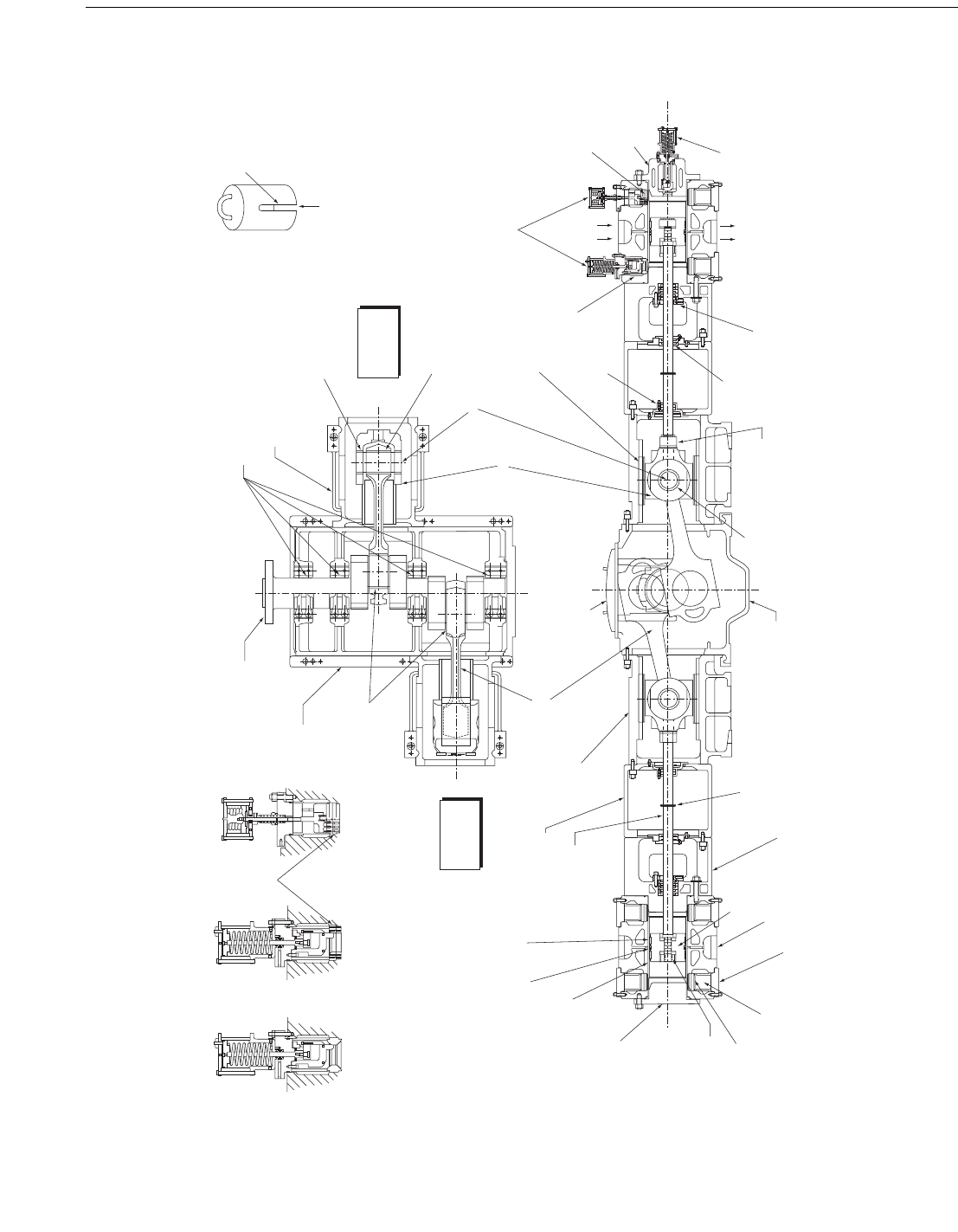
Figure J-1—Reciprocating Compressor Nomenclature
Unloader Rain
Cover
(see 6.7.11)
PLAN VIEW
ELEVATION VIEW
Motor end
Main bearings
Crosshead guide
Crosshead
pin bushing
Connecting rod
pin bushing
Crosshead pin
Crosshead
Oil pump
end
Wear bands
(rider bands)
Distance piece
Piston rod
Crosshead guide
Connecting rod
Frame cover
Crosshead
pin bushing
Piston rod
locknut
Intermediate
partition packing
Piston rod
pressure packing
Gas
discharge
Clearance
pocket
unloader
Clearance
pocket
Suction
valve
Suction valve
unloaders
Gas
inlet
Suction valve
cage
Crosshead shoe
Oil wiper
packing
Piston rings
Cylinder liner
Cylinder head
(outer end or
head end)
Piston nut
Discharge
valve
Discharge valve
cage
Valve cover
Cylinder
Piston
Oil slinger
Cylinder head
(frame end or crank end)
Frame
Crankpin bearings
Frame
Suction
valve
Crankshaft
Port or Clearance
Pocket Unloader
(see 6.7.11)
Plug Type
Unloader
(see 6.7.11)
Finger Type
Unloader
(see 6.7.11)
Slot for
unloader
tubing
Cylinder
not
shown
Cylinder
not
shown
RECIPROCATING COMPRESSORS FOR PETROLEUM, CHEMICAL, AND GAS INDUSTRY SERVICES 167
Copyright American Petroleum Institute
Provided by IHS under license with API
Licensee=IHS Employees/1111111001, User=Japan, IHS
Not for Resale, 01/01/2008 21:15:45 MST
No reproduction or networking permitted without license from IHS
--```,`,,,,`,``,,```,`,,`,,,,`-`-`,,`,,`,`,,`---

Copyright American Petroleum Institute
Provided by IHS under license with API
Licensee=IHS Employees/1111111001, User=Japan, IHS
Not for Resale, 01/01/2008 21:15:45 MST
No reproduction or networking permitted without license from IHS
--```,`,,,,`,``,,```,`,,`,,,,`-`-`,,`,,`,`,,`---

169
Annex K
(informative)
Inspector’s Checklist
This inspector’s checklist represents a summary of the potential inspection points mentioned in the main text. The final inspection
plan shall be agreed between purchaser and vendor and reflected in the quality plan.
Tab le K-1—Inspector’s Checklist
Item
Referenced
Clause API 618
Date Inspected Inspected By Status
Material Inspection 8.2.2.1
Crankshaft Ultrasonic Inspection 8.2.2.3.3
Piping Fabrication and Installation
Hydrostatic Test—Cylinders 8.3.2.1
Hydrostatic Test—Piping and Vessels 8.3.2.1
Gas Leakage Test 8.3.2.2
Shop Test 8.3.3.1
Bar-over Test Piston Rod Runout per Runout Table in Annex C 8.3.4.1
Cylinder Valve Leak Test 8.3.4.3
Additional Tests—As Specified
Crankshaft Web Deflection
Examination of Internals for Cleanliness:
Piping
Crankcase
Pulsation Suppressors
Coolers
Filters
Other
Rotation Arrow 6.16.2
Overall Dimensions and Connection Locations
a
Flange Dimensions and Finish
a
Anchor Bolt Layout and Size
a
Painting 8.4.5
Corrosion Protection—Exterior 8.4.6
8.4.17
Corrosion Protection—Interior 8.4.7
8.4.20
Corrosion Protection—Lubricated Surfaces 8.4.8
Closures of All Openings 8.4.10
8.4.11
8.4.12
Equipment Nameplate Data 6.16.2
Packing for Shipment 8.4.14
Equipment Identification 8.4.15
Piping Connections Identification (Tagging) 8.4.19
Additional Inspections—As Specified
a
Check against certified drawings.
Copyright American Petroleum Institute
Provided by IHS under license with API
Licensee=IHS Employees/1111111001, User=Japan, IHS
Not for Resale, 01/01/2008 21:15:45 MST
No reproduction or networking permitted without license from IHS
--```,`,,,,`,``,,```,`,,`,,,,`-`-`,,`,,`,`,,`---

Copyright American Petroleum Institute
Provided by IHS under license with API
Licensee=IHS Employees/1111111001, User=Japan, IHS
Not for Resale, 01/01/2008 21:15:45 MST
No reproduction or networking permitted without license from IHS
--```,`,,,,`,``,,```,`,,`,,,,`-`-`,,`,,`,`,,`---