API Std 618-2007 Reciprocating Compressors for Petroleum, Chemical, and Gas Industry Services
Подождите немного. Документ загружается.

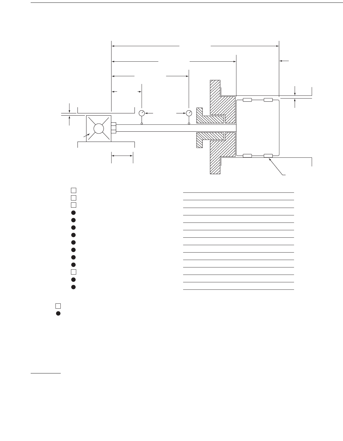
Figure C-6A—Data for Rod Runout Calculation
2EFERENCEDATA
#ALCULATIONDATA
.OTE4HECYLINDERRUNNINGCLEARANCEISTHEBORE)$
MINUSTHE/$ACROSSTHERIDERRINGS5SEACTUALVALUES
FORFINALCALCULATIONS
2ODLENGTH!
2ODLENGTH"
2ODLENGTH#
,ENGTH8
#ROSSHEADRUNNING
CLEARANCE
#ROSSHEAD
#ROSSHEADGUIDE
3TROKE
0ISTONROD
$IAL
INDICATORS
0ACKINGCASE
#%
HEAD
)NNERFACEOFCROSSHEADNUT
0ISTONLENGTH
#YLINDERRUNNING
CLEARANCE
TOTOPOFRING
0ISTON
#YLINDER
2IDERRINGS
4HROWNUMBER
3TAGE
#YLINDERBOREDIAMETER
#YLINDERRUNNINGCLEARANCE
#ROSSHEADRUNNINGCLEARANCE
3TROKE
2ODDIAMETER
2ODLENGTH!
2ODLENGTH"
2ODLENGTH#
)NDICATOR0OSITION
2ODLENGTH8)NDICATOR0OSITION
2ODMATERIAL
-ATERIALDENSITYKGM
LBIN
-ODULUSOFELASTICITY-0APSI
RECIPROCATING COMPRESSORS FOR PETROLEUM, CHEMICAL, AND GAS INDUSTRY SERVICES 121
Note: The cylinder running clearance is the bore ID minus the OD across the rider rings. Use actual values for final calculations.
Copyright American Petroleum Institute
Provided by IHS under license with API
Licensee=IHS Employees/1111111001, User=Japan, IHS
Not for Resale, 01/01/2008 21:15:45 MST
No reproduction or networking permitted without license from IHS
--```,`,,,,`,``,,```,`,,`,,,,`-`-`,,`,,`,`,,`---
Figure C-6B—Rod Runout Calculation Example
Reference Data
Calculation Dat a
Notes: The cylinder running clearance is the bore ID
minus the OD across the rider rings. Use actual values
for final calcu lations.
This exam p le is base d on US cu stom ary u nits.
Ro d l en g t h A
Ro d l en g t h B
Ro d l en g t h C
Length X
Crosshead running
clearance
Crossh ead
Crossh ead gui d e
St r o k e
Pi st on r od
Dial
indicators
Packing case
CE
head
Inner face of crosshead nut
Pi st on l en g t h
Cylinder running
clearance
(to top of ring)
Pi st o n
Cy l i n d er
Rider rings
Thr ow nu mb er
St a g e
Cylinder bore diamet er
Cylinder running clearance
Crosshead running clearance
St r o k e
Rod diameter
Ro d l en g t h A
Ro d l en g t h B
Ro d l en g t h C
Indicator Position
Ro d l en g t h X Indicator Position
Ro d m a t e r i al
Material density, kg/m
3
(lb/ in
3
)
Modulus of elasticity, MPa (psi)
1
1
20 in.
0.080 in., 0.060 in., 0.040 in., 0.020 in., 0.010 in.
0.020 in.
11 in.
3 in.
110 in.
95 in.
80 in.
14 in.
AISI 4140
0.283 lb/in.
3
30 x 10
6
psi
122 API STANDARD 618
Copyright American Petroleum Institute
Provided by IHS under license with API
Licensee=IHS Employees/1111111001, User=Japan, IHS
Not for Resale, 01/01/2008 21:15:45 MST
No reproduction or networking permitted without license from IHS
--```,`,,,,`,``,,```,`,,`,,,,`-`-`,,`,,`,`,,`---

RECIPROCATING COMPRESSORS FOR PETROLEUM, CHEMICAL, AND GAS INDUSTRY SERVICES 123
C.5.4 For correct vertical rod runout calculations, it is important to use actual measured running clearances for the cylinder and
crosshead, as well as the actual measured dimensions of the dial indicator locations along the top of the piston rod. Correct rod
lengths as required by Figure C-6A are also important.
C.5.5 Rod runout should always be measured starting with the rod at the extreme end of the stroke, with the piston at the crank
end of the cylinder. The dial indicators should be zeroed. Manual bar-over should be such that the connecting rod runs over (that
is, over the top on the outstroke) as the crosshead, piston rod, and piston are stroked slowly outward toward the end of the stroke
at the head end of the cylinder. Dial indicator readings are observed during the stroke and recorded at the end of the stroke. If this
method, and the dial indicator positions noted in C.5.3 are used as the standard measurement procedure, then field runout readings
can be properly compared and evaluated with factory runout readings provided in Figure C-3.
C.5.6 The dimensions shown in Figure C-1, Figure C-2, Figure C-5, and used in Figure C-6B for the calculation example, were
selected for convenience in illustrating basic runout geometry and principles. Dimensions for actual compressors may vary
greatly from the illustration dimensions, while some may be close or identical. Since vertical rod runout will vary according to
stroke, rod length, rod sag, and the difference in running clearances between the crosshead and cylinder, different compressors
with different cylinder configurations may have significantly different vertical runout readings for conditions of perfect
alignment.
C.5.7 Excessive rod runout is corrected by realignment and/or squaring up some or all components involved. These may
include cylinders, liners, heads, distance pieces, crossheads and crosshead guides, and rods and pistons. Crosshead threads and
face, piston rod nut threads and face, and piston rod threads may have to be checked and corrected for perpendicularity. As a
check for squareness at the interface of the crosshead and piston rod, both horizontal and vertical runout should be checked first
with the crosshead nut loose and then tight. Certain conditions of excessive rod runout at the packing case can further be
evaluated by placing an dial indicator on the rod in the cylinder through a crank end valve port to verify full length liner
concentricity with the cylinder bore and/or cylinder crank end face squareness with the bore. With a dial indicator in the cylinder,
full stroke runout cannot be taken since the dial indicator takes up some of the space between the crank-end head and the piston.
However, the available stroke is sufficient to get a suitable reading to determine alignment status
C.6 Horizontal Runout
Horizontal runout readings can be used as a direct indication of the horizontal alignment from the crosshead through the distance
pieces to the cylinder. No calculations are necessary, as horizontal runout should be within the zero limits regardless of whether
the unit is cold or hot, or of the axial location of the dial indicator along the side of the rod. It is measured by placing dial
indicators on the side of the rod as close as possible to the crosshead and the pressure packing case at the locations noted in C.5.2,
and shown in Figure C-6A. For perfect alignment, the dial indicators should read zero as the rod is moved slowly through the
entire length of the stroke during manual bar-over. The best indication of perfect horizontal alignment is when horizontal rod
runout measures zero with dial indicators set at both the crosshead end and the piston end of the rod, in other words, as close to the
packing case as possible. See 6.1.28 for allowable limit.
C.7 Vertical Runout
C.7.1 COLD RUNOUT
Cold vertical runout readings other than zero are not necessarily an indication of misalignment. When all components are
perfectly aligned, the normal cold vertical rod runout is the result of the difference between the cold running clearance of the
piston in the bore and that of the crosshead in the crosshead guide, plus the effect of normal rod sag, the length of the stroke, the
length of the rod, and the location of the dial indicators along the top of the rod. It is, therefore, important that the actual running
clearances for the cylinder and crosshead are used for the calculations, as well as the rod lengths and actual dial indicator locations
shown in Figure C-6A.
C.7.2 BASIC GEOMETRY
The basic geometry is illustrated in Figures C-1 and C-2. Piston and crosshead centerlines lie below the perfect alignment
centerline by one half of the running clearances. In cylinders where the running clearance is greater (or less) than the crosshead
running clearance, the piston will lie below (or above) the crosshead centerline by one half of the difference in the cold running
clearances. The result is basic vertical rod runout that is normally something other than zero for perfect alignment. This one-half
Copyright American Petroleum Institute
Provided by IHS under license with API
Licensee=IHS Employees/1111111001, User=Japan, IHS
Not for Resale, 01/01/2008 21:15:45 MST
No reproduction or networking permitted without license from IHS
--```,`,,,,`,``,,```,`,,`,,,,`-`-`,,`,,`,`,,`---

124 API STANDARD 618
clearance difference is referred to as the differential drop (U DROP). The basic geometry closely approximates a right triangle
condition.
Basic ideal vertical runout through the stroke length, as shown in Figure C-2, is determined by the normal running clearances and
resulting U DROP, the rod length, and the stroke. Assuming an ideal straight-rod situation, in other words, without sag, basic cold
vertical runout for perfect alignment can be calculated with sufficient accuracy using proportional right-triangle equations as
shown in Figure C-2, when these values are known. The principle can also be used to calculate U DROP at any point on the rod,
which is necessary to calculate vertical rod runout at specific dial indicator locations when combining U DROP with rod sag as
shown in Figures C-4 and C-5.
C.7.3 ROD SAG
Since all horizontal rods sag, especially those used in Types B, C, and D distance pieces, it is necessary to incorporate the effects
of deflection based on rod length, rod diameter, rod weight, and rod material into the vertical runout calculations. When vertical
rod runout readings are taken at several positions along the entire length of the piston rod, the readings will generally indicate that
sag for a long rod attached to a crosshead and to a piston, when installed in a compressor assembly with precise geometric parts
that have been proven to be perfectly aligned, will exhibit deflection characteristics similar to that for one end supported (at the
crosshead), and one end fixed (at the piston). For these reasons, it is necessary to calculate the expected vertical rod runout at the
crosshead end, and at the piston end of the rod based on Figure C-6A. Note that the data includes both dial indicator positions
along the top of the rod. The combined U DROP and deflection must be calculated at these dial indicator positions as shown in
Figures C-4 and C-5.
As can be seen from Figures C-4 and C-5, rod sag will cause different vertical runout readings at different dial indicator positions
along the top of the rod. For conditions of perfect alignment, at the lowest point of sag, runout readings may be nearly zero
depending on cylinder clearance (U DROP), while at the crosshead end, readings should always be positive. Next to the cylinder
packing case, readings may be positive, or they may be negative, depending on rod length, sag, and cylinder running clearance
(U DROP). The zero vertical runout position can usually be found by placing the dial indicator along the top of the rod until the
lowest point of sag is reached.
When the rod is stroked forward (that is, out toward the head end as noted in C.5.3 and shown in Figures C-4 and C-5), the dial
indicator at the crosshead should normally read positive.
C.8 Hot Runout
For large cylinders with aluminum pistons and Fluorocarbon wear bands, there can be a significant difference between the cold
rod runout and the hot runout. This is because of the high thermal expansion rate of the aluminum piston and the fluorocarbon
wear bands, which can result in a significant difference in the differential clearance between the piston and the crosshead. On the
other hand, there may be operating conditions involving low suction temperatures such that normal operating temperatures may
be no greater than the ambient temperature on which the cold vertical runout readings are taken. Expected hot runout can be
determined by calculating the expected thermal growth of the cylinders, the pistons, and the rider ring radial thickness. The
cylinder running clearance, affecting hot U DROP, is then adjusted accordingly in the vertical runout calculations.
Design and construction shall be aimed to achieve zero hot vertical rod runout at the packing case. Due to the effects of rod sag,
this may not always be attainable under conditions of perfect alignment; and it is necessary to determine whether the value should
be positive or negative. This can be seen from a study of Figure C-5C and the five curves illustrated by Figures C-7 through C-11.
Sometimes this requirement can be attained by shim adjustment of the crosshead shoes (see C.9), but a thorough study of cold
readings compared to expected results from computer calculations is required to determine what adjustments, if any, are needed,
or should be done to obtain the ideal desired vertical runout at operating temperatures. In many cases, where there is considerable
sag, it may be better to operate as is than attempt to adjust the vertical runout, particularly if the cylinder and crosshead guide
alignments are near perfect.
Copyright American Petroleum Institute
Provided by IHS under license with API
Licensee=IHS Employees/1111111001, User=Japan, IHS
Not for Resale, 01/01/2008 21:15:45 MST
No reproduction or networking permitted without license from IHS
--```,`,,,,`,``,,```,`,,`,,,,`-`-`,,`,,`,`,,`---
Figure C-6C—Sample Printout for Rod Runout
ROD RUNOUT
EXAMPLE OF COMPUTERIZED PRINTOUT USING THE CYLINDER DATA OF FIGURE C-5B
Note: See Figures C-6 through C-10
Rod runout at cylinder
Rod runout at crosshead
Horz runout
0.0008
0.0061
0
Calculated Runout Runout Limits
0.0025 -0.0008
0.0077 0.0044
0.0017 -0.0017
Piston rod runout calculation data
Throw number
Stage
Cylinder bore diameter
Cylinder running clearance
Crosshead running clearance
Stroke
Total rod length A
Standard calculated rod runout per Figure C-2
Vert rod runout - basis no sag
Hor rod runout
Rod sag calculation data
rod diameter
rod length B
material density lb/in
3
modulus of elasticity E
Moment of inertia I
Total rod weight
Maximum deflection piston end fixed per
Figure C-3
1
1
20.00
0.080
0.020
11
110
0.0030
0
3
95
0.2830
3.00e+07
3.9761
190.0
0.007398
Ref: rod runout
At crosshead At cylinder
0.0061 0.0008
Ref: piston $ DROP = 0.030
Enter rod lengths as integers only
Limits
0.0047 0.0014
0.0017 -0.0017
Rod material AISI 4140
Max at D = 0.4215 x length =
40.04 in. from free end (crosshead)
Ref: nominal runout due to sag = 0.0026
U.S. customary units
By: EngineeringPiston rod runout calculation Ref:
Customer:
Size unit:
Runout sample
Runout
11 in. stroke
0.080
0.060
0.040
0.020
0.010
Cylinder Running
Clearance (in.)
Crosshead Running
Clearance (in.)
Rod Runout (in.)
ROD RUNOUT AT DIFFERENT CYLINDER CLEARANCES
At Crosshead
At Cylinder
$DROP
0.020
0.020
0.020
0.020
0.020
0.030
0.020
0.010
0.000
-0.005
0.0061
0.0051
0.0041
0.0031
0.0026
+0.0008
-0.0002
-0.0012
-0.0022
-0.0027
RECIPROCATING COMPRESSORS FOR PETROLEUM, CHEMICAL, AND GAS INDUSTRY SERVICES 125
Copyright American Petroleum Institute
Provided by IHS under license with API
Licensee=IHS Employees/1111111001, User=Japan, IHS
Not for Resale, 01/01/2008 21:15:45 MST
No reproduction or networking permitted without license from IHS
--```,`,,,,`,``,,```,`,,`,,,,`-`-`,,`,,`,`,,`---
Figure C-7—Graphical Illustration of Rod Runout at 0.080 in. Cylinder Running Clearance
0.002
0
0.004
0.006
0.008
0.010
0.012
0.014
0.016
0.018
0.020
0.022
0.024
0.026
0.028
0.030
0.032
0778899 11011 22 33 44 55 66
X
C
A
B
Piston rod
Rod
sag
$DROP0.030 in.
0.020 in. Crosshead
clearance
0.080 in. Cylinder
clearance
14 in.
Dial indicator
at crosshead
80 in.
Dial
indicator
at cylinder
95 in.
CE face
of piston
HE face
of piston
Runout 0.0061 in.
at crosshead
Runout 0.0008 in.
at cylinder
REF: FIG C-5C
ROD LENGTH
DEFLECTION / RUNOUT
Crosshead centerline
VERTICAL ROD RUNOUT
Face of crosshead
126 API STANDARD 618
Copyright American Petroleum Institute
Provided by IHS under license with API
Licensee=IHS Employees/1111111001, User=Japan, IHS
Not for Resale, 01/01/2008 21:15:45 MST
No reproduction or networking permitted without license from IHS
--```,`,,,,`,``,,```,`,,`,,,,`-`-`,,`,,`,`,,`---
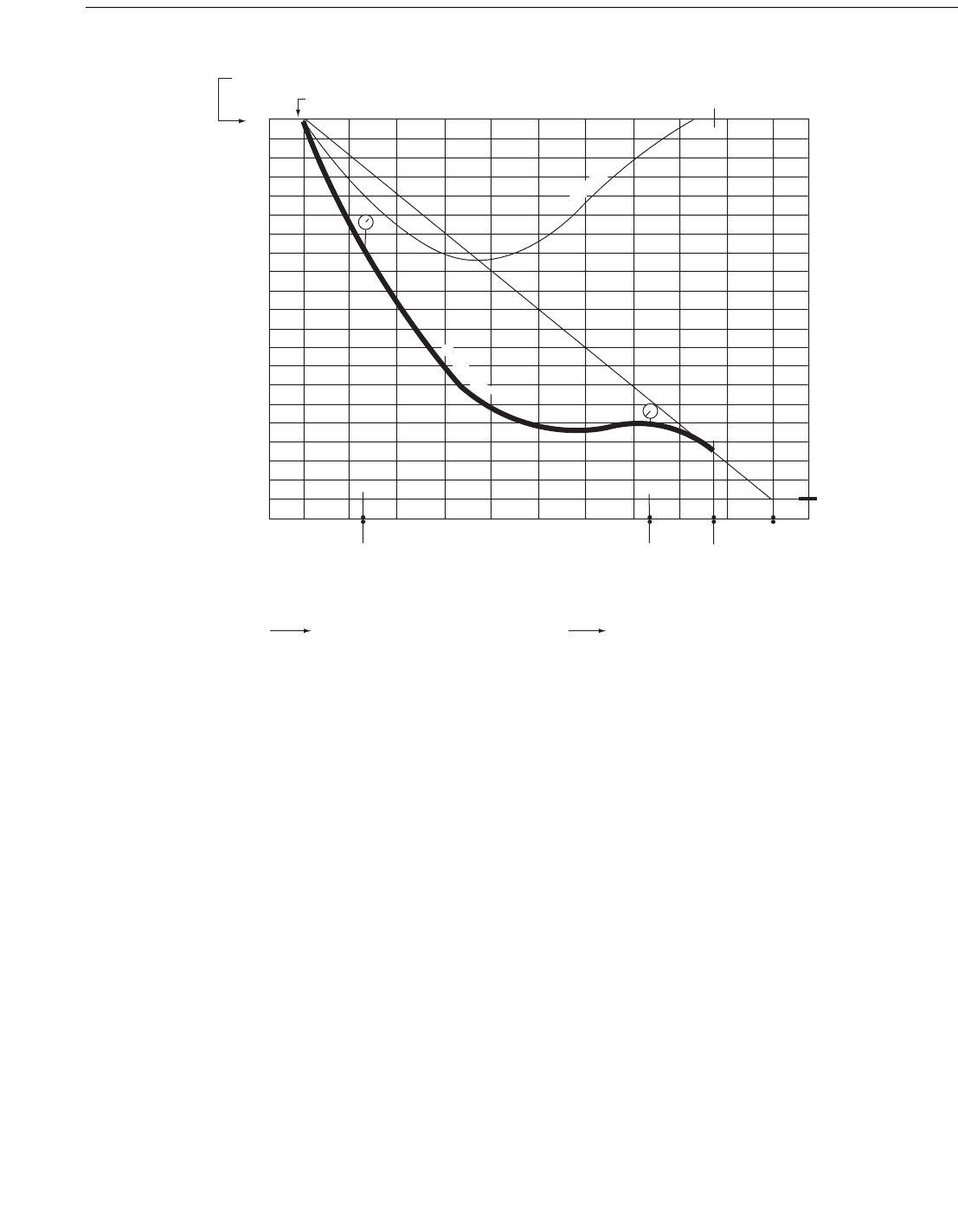
Figure C-8—Graphical Illustration of Rod Runout at 0.060 in. Cylinder Running Clearance
0.001
0
0.002
0.003
0.004
0.005
0.006
0.007
0.008
0.009
0.010
0.011
0.012
0.013
0.014
0.015
0.016
0.017
0.018
0.019
0.020
0.021
0112233445566778899 110
X
C
B
A
VERTICAL ROD RUNOUT
14 in.
Dial
indicator
at crosshead
80 in.
Dial
indicator
at cylinder
95 in.
CE face
of piston
HE face
of piston
Runout + 0.0051 in.
at crosshead
Runout = –0.0002 in.
at cylinder
REF: FIG C-5C
ROD LENGTH
0.020 in. Crosshead
clearance
0.060 in. Cylinder
clearance
Same as removing
0.010 in. shims from
bottom shoe of
crosshead relative to
Fig. C-6. Changes
rod runout by 0.001 in.
$DROP0.020 in.
DEFLECTION / RUNOUT
Piston rod
Rod sag
Crosshead centerline
Face of crosshead
RECIPROCATING COMPRESSORS FOR PETROLEUM, CHEMICAL, AND GAS INDUSTRY SERVICES 127
Copyright American Petroleum Institute
Provided by IHS under license with API
Licensee=IHS Employees/1111111001, User=Japan, IHS
Not for Resale, 01/01/2008 21:15:45 MST
No reproduction or networking permitted without license from IHS
--```,`,,,,`,``,,```,`,,`,,,,`-`-`,,`,,`,`,,`---
Figure C-9—Graphical Illustration of Rod Runout at 0.040 in. Cylinder Running Clearance
X
X A
B
B
0
–0.001
–0.002
–0.003
–0.004
–0.005
–0.006
–0.007
–0.008
–0.009
–0.010
–0.011
–0.012
0112233445566778899 110
DEFLECTION / RUNOUT
VERTICAL ROD RUNOUT
14 in.
Dial
indicator
at crosshead
80 in.
Dial
indicator
at cylinder
95 in.
CE face
of piston
HE face
of piston
Runout = + 0.0041 in.
at crosshead
Runout = –0.0012 in.
at cylinder
REF: FIG C-5C
ROD LENGTH
0.020 in. Crosshead
clearance
0.040 in. Cylinder
clearance
Same as removing
0.020 in. shims from
bottom shoe of
crosshead relative to
Fig. C-6. Changes
rod runout by 0.002 in.
$DROP0.010 in.
Piston rod
Crosshead centerline
Face of crosshead
Rod sag
128 API STANDARD 618
Copyright American Petroleum Institute
Provided by IHS under license with API
Licensee=IHS Employees/1111111001, User=Japan, IHS
Not for Resale, 01/01/2008 21:15:45 MST
No reproduction or networking permitted without license from IHS
--```,`,,,,`,``,,```,`,,`,,,,`-`-`,,`,,`,`,,`---
Figure C-10—Graphical Illustration of Rod Runout at 0.020 in. Cylinder Running Clearance
X
C
B
A
0
–0.001
–0.002
–0.003
–0.004
–0.005
–0.006
–0.007
–0.008
0 112233445566778899 110
14 in.
Dial
indicator
at crosshead
80 in.
Dial
indicator
at cylinder
HE face
of piston
Runout = + 0.0031 in.
at crosshead
Runout = – 0.0022 in.
at cylinder
REF: FIG C-5C
ROD LENGTH
DEFELCTION / RUNOUT
VERTICAL ROD RUNOUT
$DROP0.0 in.
Crosshead and
piston on same
centerline
0.020 in. Crosshead
clearance
0.020 in. Cylinder
clearance
Same as removing
0.030 in. of shims from
bottom shoe of
crosshead relative to
Fig. C-6. Changes
rod runout by 0.003 in.
Crosshead centerline
Face of crosshead
95 in.
CE face
of piston
Piston rod = Rod sag
RECIPROCATING COMPRESSORS FOR PETROLEUM, CHEMICAL, AND GAS INDUSTRY SERVICES 129
Copyright American Petroleum Institute
Provided by IHS under license with API
Licensee=IHS Employees/1111111001, User=Japan, IHS
Not for Resale, 01/01/2008 21:15:45 MST
No reproduction or networking permitted without license from IHS
--```,`,,,,`,``,,```,`,,`,,,,`-`-`,,`,,`,`,,`---
Figure C-11—Graphical Illustration of Rod Runout at 0.010 in. Cylinder Running Clearance
–0.006
–0.005
–0.004
–0.003
–0.002
–0.001
0.000
0.001
0.002
0.003
0.004
0.005
0.006
0.007
0.008
0112233445566778899 110
X
C
A
B
14 in.
Dial
indicator
at crosshead
80 in.
Dial
indicator
at cylinder
95 in.
CE face
of piston
HE face
of piston
Runout + 0.0026 in.
at crosshead
Runout = –0.0027 in.
at cylinder
ROD LENGTH
0.020 in. Crosshead
clearance
0.010 in. Cylinder
clearance
Less cylinder
clearance than
crosshead clearance
$DROP–0.005 in.
DEFLECTION / RUNOUT
Rod sag
Piston rod
Crosshead centerline
Face of crosshead
VERTICAL ROD RUNOUT
130 API STANDARD 618
C.9 Vertical Runout Adjustment
C.9.1 If it is believed that some adjustment is necessary to the vertical runout readings, it must first be assured that cylinder
alignment and cylinder level are properly set so that the components are free of harmful stresses at operating conditions. If
crosshead shim adjustment is then considered necessary by interchanging shims under the crosshead shoes, it should be
remembered that taking shims from the bottom shoe and placing them under the top shoe drops the crosshead centerline further
below the perfect alignment centerline. This decreases the U DROP and thus decreases the positive rod runout at the crosshead,
but may actually increase negative runout at the packing case due to sag. This is illustrated on Figure C-5C and in the series of
five runout curves of Figures C-6 through C-10.
With reference to Figures C-6 and C-9, note that a 0.76 mm (0.030 in.) change of shims, that would put the crosshead and piston
on the same centerline such that U DROP = 0.00, changes the runout by only 0.076 mm (0.003 in.), that is, the crosshead runout
goes to +0.079 mm (+0.0031 in.) from +0.155 mm (+0.0061 in.), and the runout at the packing case goes to –0.056 mm (–0.0022
in.) from +0.020 mm (+0.0008 in.). In other words, for this example, rod runout is changed by only 0.0254 mm (0.001 in.) for
each 0.254 mm (0.010 in.) of shims removed from the bottom shoe in an attempt to lower the crosshead closer to the centerline of
the cylinder. Because rod length and rod diameter, which affect sag, and cylinder size, which affects running clearance, can
significantly affect vertical runout, every compressor cylinder assembly must be fully evaluated for expected vertical runout
based on perfect alignment conditions. If crosshead shims are shifted in an attempt to adjust vertical runout, it is important that the
crosshead always be installed with the “top” side up following removal for maintenance.
Copyright American Petroleum Institute
Provided by IHS under license with API
Licensee=IHS Employees/1111111001, User=Japan, IHS
Not for Resale, 01/01/2008 21:15:45 MST
No reproduction or networking permitted without license from IHS
--```,`,,,,`,``,,```,`,,`,,,,`-`-`,,`,,`,`,,`---