API RP 14FZ-2001 Recommended Practice for Design and Installation of Electrical Systems for Fixed and Floating Offshore Petroleum Facilities for Unclassified and Class I, Zone 0, Zone 1 and Zone 2 Locations
Подождите немного. Документ загружается.


DESIGN AND INSTALLATION OF ELECTRICAL SYSTEMS FOR FIXED AND FLOATING OFFSHORE PETROLEUM FACILITIES
FOR UNCLASSIFIED AND CLASS I, ZONE 0, ZONE 1, AND ZONE 2 LOCATIONS
51
Figure 8—Typical Class I, Zone 1 or Zone 2 Electrical Installation Conduit and Cable Connections to Flammable
Fluid Process-Connected Nonarcing Devices with Multiple-Seal Diaphragms or Tubes
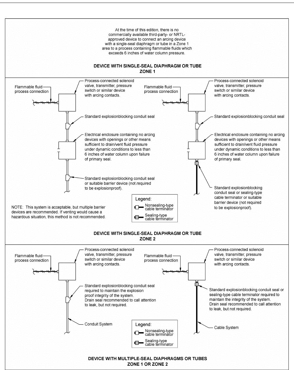
52 API RECOMMENDED PRACTICE 14FZ
Figure 9—Typical Class I, Zone 1 or Zone 2 Electrical Installation Conduit or Cable Connections to Flammable Fluid
Process-Connected Arcing Devices

DESIGN AND INSTALLATION OF ELECTRICAL SYSTEMS FOR FIXED AND FLOATING OFFSHORE PETROLEUM FACILITIES
FOR UNCLASSIFIED AND CLASS I, ZONE 0, ZONE 1, AND ZONE 2 LOCATIONS
53
6.8.2.3.2 If drain seals are utilized at an area classification
boundary, care should be exercised in the placement of such
seals to ensure that gases or vapors cannot be communicated
across the boundary through the conduit system by way of the
seal’s drain passage. Figure 10 illustrates proper and improper
placement of drain seals at classification boundaries.
6.8.2.3.3 Cables with a gas/vaportight continuous sheath
do not have to follow the same sealing requirements as con-
duit systems when crossing area classification boundaries.
Such cables are not required to be sealed unless the cable is
attached to process equipment or devices that may cause a
pressure in excess of 6 in. of water (1493 Pascals) to be
exerted at a cable end, in which case a seal, barrier or other
means shall be provided to prevent migration of flammable
fluids into an unclassified location or to arcing or high-tem-
perature devices in other portions of the system (in accor-
dance with NEC Article 501). No seal is then required at the
boundary location. Cables with a gas/vaportight impervious
continuous sheath are permitted to pass through an area clas-
sification boundary without seals. Cables that do not have a
gas/vaportight continuous sheath shall be sealed at the bound-
ary of the Zone 2 and unclassified location.
6.8.2.3.4 For additional information on seals for classified
area boundaries, refer to NEC 501-5.
6.8.3 Installation
In addition to being placed in proper locations, the following
practices should be observed when installing sealing fittings:
a. Sealing fittings should be accessible.
b. Sealing fittings should be mounted only in the position(s)
for which they were designed. Some seals are designed only
to be installed vertically; some can be installed either verti-
cally or horizontally; a third type can be installed in any
position.
c. Pouring hubs should be properly oriented. The hub
through which the sealing compound is to be poured should
be installed above the sealing cavity to properly pour the seal.
d. Only sealing compound and fiber approved for a particular
sealing fitting shall be used, and the manufacturer’s instruc-
tions should be followed for the preparation of dams (if appli-
cable) and the preparation and installation of the sealing
compound.
e. No splices or taps are allowed in seals. Sealing compounds
are not insulating materials and may absorb moisture, causing
grounding of the circuit conductors.
f. Seals with drain provisions should be installed to allow
drainage of conduits where water or other liquids may accu-
mulate in the conduit system. See Figure 10 for the proper
placement of drain seals.
g. Factory-sealed devices, such as toggle switches, push-but-
tons, lighting panels, and lighting fixtures, eliminate the need
for externally sealing those particular devices, except for
cables in Zone 1 locations. However, a factory seal for one
device cannot be used in place of a seal for another device
unless specifically approved for that purpose. Most factory-
sealed devices and enclosures have been designed and tested
to withstand an explosive pressure from within their own
enclosures only, and not from an explosive pressure from the
opposite direction.
6.9 CIRCUIT PROTECTION
6.9.1 General
6.9.1.1 The purpose of a circuit protection device is to
open a circuit before a conductor (or its insulation or shield)
is damaged by an overcurrent or through fault condition.
These devices also protect system components such as bus
structures, motor starters, transformers, and lighting panels,
which have limited current-carrying and short-circuit ratings
and which will be damaged if these ratings are exceeded. To
accomplish these objectives, circuit-protection devices should
meet the following:
a. The device should be sized to automatically interrupt the
flow of abnormal currents without damage to conductors or
equipment.
b. The device should be rated to continuously carry design
load currents at design voltage.
c. The interrupting capacity of the device should equal or
exceed available short circuit currents.
6.9.1.2 Two devices used for circuit protection are fuses
and circuit breakers. Some advantages and disadvantages to
be considered when selecting circuit protective devices are
listed in Table 6-9.
6.9.1.3 With few exceptions, that are defined in NEC Arti-
cle 240, Overcurrent Protection, the NEC requires that all
conductors be protected by means of a fuse or circuit breaker
of a rating not greater than the conductor’s current carrying
capacity. For example, a single conductor No. 12 AWG 75°C
copper wire should be protected with no larger than a 20-
ampere fuse or breaker. This rule prohibits (with specific
exceptions discussed in NEC Article 240) the practice of tap-
ping a conductor with a small conductor without providing
proper overcurrent protection for the smaller conductor at the
point of the tap.
6.9.1.4 Circuit-protection devices should be coordinated
with upstream and downstream circuit-protection devices to
provide selectivity such that only the circuit-protective device
immediately upstream of the overload or short circuit condi-
tion will open.
6.9.2 Circuit Breaker Selection
6.9.2.1 Molded case circuit breakers normally used on low
voltage power distribution systems are widely used in classi-

54 API RECOMMENDED PRACTICE 14FZ
Figure 10—Typical Class I, Zone 1 or Zone 2 Electrical Installation Placement of Drain Seals

DESIGN AND INSTALLATION OF ELECTRICAL SYSTEMS FOR FIXED AND FLOATING OFFSHORE PETROLEUM FACILITIES
FOR UNCLASSIFIED AND CLASS I, ZONE 0, ZONE 1, AND ZONE 2 LOCATIONS
55
fied locations due to their availability in approved explosion-
proof enclosures. Molded-case-type circuit breakers should
meet the requirements of UL 489. Thermal magnetic breakers
should be used for all circuit-breaker applications, except as
an integral part of combination motor starters where magnetic
only breakers are recommended. Thermal magnetic circuit
breakers are sized by both frame size and trip rating. Each
frame size is available with several trip ratings. The magnetic
(instantaneous) setting is usually nonadjustable for smaller-
sized thermal magnetic breakers. This magnetic trip, where
adjustable, should be set at the lowest value that will not trip
under maximum inrush conditions. Thermal magnetic break-
ers should be loaded only to 80% of their trip rating unless
rated for 100% continuous load.
6.9.2.2 Power circuit breaker usage normally is limited to
generator breaker or large-sized feeder breaker applications.
Low and medium voltage power circuit breakers should meet
the requirements listed in section 5.5.3. Some of the signifi-
cant features of power circuit breakers follow:
a. Remote operation capability.
b. Spring-operated (stored energy) closing and opening.
c. Fixed mount (available in low voltage only) or drawout
type.
d. Availability of 1) “instantaneous” and “long time”, 2)
“short time” and “long time”, and 3) “instantaneous”, “short
time” and “long time” trip units.
e. Availability of multiple auxiliary contacts.
f. Adaptability to protective relaying.
6.10 GROUNDING
6.10.1 General
There are two types of grounding, described below. System
grounding primarily is concerned with the protection of elec-
trical equipment by stabilizing voltages with respect to
ground. Equipment grounding primarily is concerned with
the protection of personnel from electric shock by maintain-
ing the potential of noncurrent-carrying equipment at or near
ground potential.
6.10.2 System Grounding
6.10.2.1 All generators and other separately derived sys-
tems directly feeding single-phase loads that utilize a neutral
should have their neutrals solidly grounded. This would apply
normally to 120/240 volt single-phase and 208Y/120 or
480Y/277 volt three-phase systems. Three-phase systems
feeding only three-phase loads or single-phase loads not
using a neutral may be operated solidly grounded, or, if the
line-to-neutral voltage is greater than 150 volts, ungrounded,
high impedance grounded or low impedance grounded.
The choice of system ground will vary with the specific
application and system design. For additional discussion on
grounding, refer to IEEE Std 142.
6.10.2.2 For sizing system grounding conductors, refer to
NEC Table 250-66.
6.10.2.3 Any grounded, separately-derived system shall be
connected to ground at only one point. If systems are operat-
ing in parallel, these systems may be individually grounded,
or grouped for grounding, at a common point. At all other
points any grounded neutral conductor (including the neutral
in lighting panels, bus boxes, power supplies, and electronic
equipment) shall be insulated from ground.
6.10.2.4 Each individual neutral conductor should have
white or natural gray insulation or be identified with a white
marking or other equally effective means at each termination
and accessible box opening throughout the system. Green
insulated conductors shall not be re-identified (re-marked) as
neutral conductors or phase conductors.
Table 6-9—Circuit Protection Devices—Advantages
and Disadvantages
Circuit Breakers
Advantages
1. Prevent single phasing.
2. More suitable for remote operation.
3. Resettable operation without replacement.
4. Discourage improper replacement.
5. More suitable for XP enclosures.
6. More suitable for GFI installations.
7. Available with shunt trip or low voltage release options.
Disadvantages
1. Moderate operating speed.
2. Limited interrupting capacities for larger frame sizes.
3. Mechanically complex and not necessarily fail-safe.
Fuses
Advantages
1. Mechanically simple and fail-safe.
2. Fast operating speed.
3. High interrupting capacities.
4. More easily coordinated.
5. Greater size selection available.
Disadvantages
1. Nonrepetitive operations.
2. Require proper procedures for safe replacement.
3. Spare inventory required.
4. Possible single phasing.
5. Subject to replacement with an improperly rated fuse.

56 API RECOMMENDED PRACTICE 14FZ
6.10.2.5 The facility structure or hull of a floating facility
should not serve as a current-carrying conductor except for
the following systems:
a. Cathodic protection systems.
b. Limited and locally grounded systems, such as battery
systems for engine starting and control that have a one-wire
system and have the ground lead connected to the engine.
c. Insulation level monitoring devices with circulating cur-
rents not exceeding 30 mA.
d. Welding systems with a structure or hull return.
Note: When welding on facilities with the welding machine located
on an adjacent vessel or barge, the facilities should be effectively
bonded to the vessel or barge to avoid galvanic corrosion of the facil-
ity or the vessel.
e. Ground-fault detection systems.
6.10.3 Equipment Grounding
6.10.3.1 Grounding of electrical equipment on fixed and
floating offshore petroleum facilities in a positive manner is
of particular importance because personnel standing on steel
decks or in contact with steel framing present a low imped-
ance path to ground, effectively grounded. In addition, the
dampness and salt spray contribute to the breakdown of insu-
lation and to the possibility of leakage on the surface of insu-
lators and similar devices. On platforms with wooden or con-
crete decks, equipment-grounding conductors should be
installed between electrical equipment and a grounding net-
work. It is recommended that all metal equipment, such as
buildings, skids, and vessels be grounded to the steel structure
or grounding network. Exposed, noncurrent-carrying metal
parts of fixed equipment that may become energized because
of any condition shall be grounded. Equipment that is welded
to the structure or deck is considered to be adequately
grounded. The physical contact obtained when equipment is
bolted to a steel structure is not necessarily an adequate effec-
tive ground because of paint and possible corrosion. Exposed,
noncurrent-carrying metal parts of portable electrical equip-
ment shall be grounded through a conductor in the supply
cable to the grounding pole in the receptacle.
6.10.3.2 For sizing equipment grounding conductors, refer
to NEC Table 250-122.
6.10.3.3 Each individual grounding conductor should be
bare, or, if insulated, have a continuous outer finish that is
either green or green with one or more yellow stripes. Alter-
natively, the grounding conductor can be identified with a
green marking or other equally effective means at each termi-
nation and accessible box opening throughout the system.
Conductors with green insulation or markings shall not be
used for any purpose other than grounding.
6.10.3.4 To provide the desired safety, equipment ground-
ing should accomplish the following:
a. Grounding should limit the voltage (normally to 42 V
maximum) that may be present between the equipment in
question and any other grounded object with which personnel
may be in contact at the same time.
b. For solidly grounded systems, grounding should present a
low impedance path for short circuit current to return to the
source of power, thus opening a fuse or tripping a circuit
breaker. This requires that the equipment ground be bonded
to the system ground.
6.10.4 Ground Fault Indication
6.10.4.1 A ground fault indication system should be
installed on each separately-derived AC electrical power dis-
tribution system (e.g., generators and transformers) that is not
solidly or low impedance grounded. This system should be
designed to provide an indication of a ground fault condition,
with the ground fault indicators provided at a location(s) that
is commonly accessed by operating personnel. Separate,
ground-fault indication systems are not required when ground
fault protection systems are provided.
6.10.4.2 All armor or other metal coverings of cable shall
be electrically continuous throughout the entire length and
shall be effectively grounded. It is recommended that metal
coverings be grounded at all terminations.
6.11 ELECTRICAL ENCLOSURES
6.11.1 General
Electrical conductors, buses, terminals, or components that
present a shock hazard are not permitted to be uninsulated if
exposed.
6.11.1.1 Electrical equipment enclosures are provided for
both personnel and equipment protection. For offshore use, it
is recommended that enclosures be constructed of corrosion-
resistant materials, such as copper-free aluminum, stainless
steel (Type 316 usually preferred because Type 303 and 304
are more subject to pitting-type corrosion), suitable plastic,
fiberglass, or hot-dipped galvanized steel. Enclosure hard-
ware constructed of Type 316 stainless steel is recommended.
6.11.1.2 Refer to Table 6-10 for a listing and description of
various NEMA enclosures available. For additional informa-
tion, see NEMA ICS6 and NEMA 250. Refer to Table 6-11
for a listing and description of various IEC enclosures avail-
able. For additional information, see IEC 529. Refer to
NEMA MG 1 for additional information concerning enclo-
sures for rotating apparatus.
6.11.1.3 Space heaters, breathers, or drains, or a combina-
tion of such, should be considered for all enclosures as a

DESIGN AND INSTALLATION OF ELECTRICAL SYSTEMS FOR FIXED AND FLOATING OFFSHORE PETROLEUM FACILITIES
FOR UNCLASSIFIED AND CLASS I, ZONE 0, ZONE 1, AND ZONE 2 LOCATIONS
57
means of preventing internal moisture buildup and conse-
quent, equipment-corrosion damage.
6.11.1.4 Interior electrical equipment exposed to dripping
liquids or falling solid particles should be manufactured to at
least NEMA Type 2 or IEC IP 32 degree of protection, as
appropriate for the service intended.
6.11.1.5 Electrical equipment in locations exposed to seas,
splashing, pressure-directed liquids, or similar moisture con-
ditions should be manufactured to meet at least a NEMA
Type 4 or 4X or IEC IP 55 or 56 rating, as appropriate for the
service intended.
6.11.1.6 It is recommended that electrical equipment in
locations exposed to weather, but not exposed to the condi-
tions defined in 6.11.1.5, be manufactured to meet NEMA 4,
4X or 7, or IEC 55 or 56. Explosionproof or flameproof
enclosures may not provide protection against the ingress of
water; breathers and drains may be required to prevent the
accumulation of moisture.
6.11.1.7 Electrical equipment subject to submersion
should be manufactured to meet at least a NEMA Type 6 or
6P or IEC IP 67 degree of protection, as appropriate for the
service intended.
6.11.1.8 Each enclosure should be selected such that the
total rated temperature of the equipment inside the enclosure
is not exceeded.
6.11.1.9 Equipment enclosures for interior locations not
subject to dripping liquids or falling solid particles should be
manufactured to at least NEMA Type 1 or IEC IP 10, as
appropriate for the service intended. Most consumer products
(e.g., personal computers, copy machines, facsimile (fax)
machines and televisions) are not NEMA-rated but are per-
missible in such interior locations.
Table 6-10—NEMA Enclosures
NEMA
Type
No. Type of Enclosure Characteristics Intended Use
Typical Offshore
Applications
1 General Purpose,
Surface Mounting
A general-purpose (NEMA Type 1) enclosure is designed
to meet the latest general specifications for enclosures of
Underwriters' Laboratories. This enclosure is intended pri-
marily to prevent accidental contact with enclosed electrical
apparatus. A NEMA Type 1 enclosure is suitable for gen-
eral-purpose application indoors where atmospheric condi-
tions are normal. It is not dusttight or watertight.
To prevent accidental
contact with live parts,
indoors, where normal
atmospheric conditions
prevail.
Lighting panels, motor
control centers, discon-
nect switches, etc., in
unclassified locations
inside buildings.
1-A Semi-Dusttight A semi-dusttight enclosure (NEMA Type 1-A) is similar to
the Type 1 enclosure, but with the addition of a gasket
around the cover.
A NEMA Type 1-A enclosure is suitable for general-pur-
pose application indoors and provides additional protection
against dust, although it is not dusttight.
Same as NEMA Type 1,
but in locations where a
small amount of dust is
prevalent.
Same as NEMA Type 1.
1-B General Purpose,
Flush Mounting
A flush-type enclosure (NEMA Type 1-B) is similar to the
Type 1 enclosure, but is designed for mounting in a wall
and is provided with a cover that also serves as a flush plate.
Same as NEMA Type 1,
but for flush-type
mounting applications
Same as NEMA Type 1
where flush (versus sur-
face) mounting is
desired.
2 Driptight A driptight enclosure (NEMA Type 2), also referred to as
“Dripproof”, is similar to the Type 1 general purpose enclo-
sure, but with the addition of drip shields or their equiva-
lent. A Type 2 enclosure is suitable for application where
condensation may be severe.
Note: Driptight apparatus may be semi-enclosed apparatus
if it is provided with suitable protection integral with the
apparatus, or so enclosed as to exclude effectively falling
solid or liquid material.
Locations where con-
densation may be
severe.
No typical offshore
applications.
3 Weathertight A weathertight enclosure (NEMA Type 3) is designed for
use outdoors to provide protection against weather hazards
such as rain and sleet.
A NEMA Type 3 enclosure is suitable for application out-
doors.
Outdoors where it is
necessary to provide
protection against
weather hazards such as
rain and sleet.
Refer to NEMA Type
12 applications.
3R Weather-Resistant A weather-resistant enclosure (NEMA Type 3R) is designed
for use outdoors to provide protection against rain. Rain will
not readily interfere with operation of internal components.
NEMA Type 3R provides less protection than Type 3.
Same as NEMA Type 3,
but in less severe appli-
cation.
Same as NEMA Type 3

58 API RECOMMENDED PRACTICE 14FZ
4 Watertight A watertight enclosure (NEMA Type 4) is designed for
outdoor use and is required to meet the hose test as fol-
lows: NEMA Type 4 Enclosures shall be tested by subjec-
tion to a stream of water. A hose with a 1-in. nozzle shall
be used and shall deliver at least 65 gallons per minute.
The water shall be directed on the enclosure from a dis-
tance of not less than 10 feet and for a period of 5 minutes.
During this period it may be directed in one or more direc-
tions as desired. There shall be no leakage of water into
the enclosure under these conditions.
Outdoor or indoor loca-
tions where enclosed
equipment might be
subjected to splashing
or dripping water. Not
suitable for submersion
in water.
Equipment enclosures
and junction boxes sub-
ject to wind-driven rain
or hose washdown.
4X Watertight A watertight corrosion-resistant (NEMA Type 4X) enclo-
sure is similar to the Type 4 enclosure but is manufactured
from corrosion-resistant materials, such as glass polyester
or stainless steel.
Same as NEMA Type 4,
but designed for a more
corrosive environment.
Same as NEMA Type 4.
5 Dusttight A dusttight (NEMA Type 5) enclosure is provided with gas-
kets and is suitable for application in locations where it is
desirable to exclude dirt
In locations where it is
necessary to protect the
enclosed equipment
against injurious accu-
mulation of dust or lint
No typical offshore
applications.
6, 6P Submersible A submersible enclosure is suitable for applications where
the equipment may be subject to occasional temporary sub-
mersion (NEMA Type 6) and prolonged submersion
(NEMA Type 6P) in water. The design of the enclosure will
depend upon the specified conditions of pressure and time.
Locations where the
equipment is subject to
submersion in water.
Junction boxes
installed in the splash
zone.
7 Explosionproof,
Class I
An explosionproof enclosure (NEMA Type 7) is designed
to meet the application requirements in Art. 500 of the NEC
for Class I locations and is designed in accordance with the
latest specifications of Underwriters' Laboratories for par-
ticular groups of gases. Certain NEMA 7 enclosures are
approved for several groups (such as Groups B, C, and D),
while others may be approved only for a particular group
(such as Group D). NEMA 7 enclosures are not necessarily
suitable for outdoor use.
Locations classified as
Class I, Division 1 or 2
hazardous locations.
Widely used in classi-
fied locations when arc-
ing or high temperature
devices are utilized.
8 Explosionproof,
oil-filled, Class I
An explosionproof, oil filled enclosure (NEMA Type 8) is
designed to meet the application requirements in Art. 500 of
the NEC for Class I locations and is designed in accordance
with the latest specifications of Underwriters' Laboratories
for specific gases. The apparatus is immersed in oil.
Same as NEMA Type 7. Not widely utilized off-
shore, but suitable for
same areas as NEMA
Type 7.
9 Dust-Ignition Proof,
Class II
A dust-ignition proof enclosure (NEMA Type 9) is
designed to meet the application requirements in Art. 500 of
the NEC for Class II locations, and is designed in accor-
dance with the latest specifications of Underwriters' Labo-
ratories for particular dusts.
Locations classified as
Class II hazardous loca-
tions (containing com-
bustible dust).
No typical offshore
applications.
10 A Type 10 enclosure is designed to meet the latest require-
ments of the Bureau of Mines and is suitable for applica-
tions in coal mines.
Locations required to
meet the latest require-
ments of the Bureau of
Mines.
No typical offshore
applications.
11 Acid and fume resis-
tant, oil immersed
An acid and fume-resistant (NEMA Type 11) enclosure is
suitable for applications indoors where the equipment may
be subject to corrosive acid or fumes. The apparatus is
immersed in oil.
Locations where acid or
fumes are present.
No typical offshore
applications.
Table 6-10—NEMA Enclosures
NEMA
Type
No. Type of Enclosure Characteristics Intended Use
Typical Offshore
Applications

DESIGN AND INSTALLATION OF ELECTRICAL SYSTEMS FOR FIXED AND FLOATING OFFSHORE PETROLEUM FACILITIES
FOR UNCLASSIFIED AND CLASS I, ZONE 0, ZONE 1, AND ZONE 2 LOCATIONS
59
12 Dusttight and Drip-
tight
A dusttight and driptight (NEMA Type 12) enclosure is
provided with an oil-resistant synthetic gasket between the
case and the cover. To avoid loss, any fastener parts are
held in place when the door is opened. There are no holes
through the enclosures for mounting or for mounting con-
trols within the enclosure and no conduit knockouts or con-
duit openings. Mounting feet or other suitable means for
mounting are provided.
A NEMA Type 12 enclosure is suitable for industrial appli-
cation in locations where oil or coolant might enter the
enclosure. NEMA type 12 enclosures are not suitable for
outdoor use, but may be modified to meet Type 3 require-
ments with the addition of a drip shield. Enclosures carry-
ing a NEMA 3.12 rating area superior to those carrying
only a NEMA 3 rating.
Indoor locations where
oil or coolant might
enter the enclosure.
Indoors in areas pro-
tected from the environ-
ment, or outdoors when
modified, to meet
NEMA Type 3 require-
ments.
13 Oiltight and Dusttight An oiltight and dusttight (NEMA 13) enclosure is intended
for use indoors primarily to house pilot devices such as
limit switches, push buttons, selector switches pilot, lights,
etc., and to protect these devices against lint and dust, seep-
age, external condensation, and spraying of water, oil or
coolant. They have oil-resistant gaskets and, when intended
for wall or machine mounting, have mounting means exter-
nal to the equipment cavity. They have no conduit knock-
outs or unsealed openings providing access into the
equipment cavity. All conduit openings have provision for
oiltight conduit entry.
Indoor locations where
spraying oil or coolant
might enter the enclo-
sure.
Indoors in areas pro-
tected from the environ-
ment for control panels.
Table 6-11—Degree of Protection of Enclosures in Accordance with IEC 60529
First Number
Degree of Protection Against Solid Objects
Second Number
Degree of Protection Against Water
0 Nonprotected. 0 Nonprotected
1 Protected against a solid object greater than 50 mm, such as a hand. 1 Protected against water dripping vertically, such as condensation.
2 Protected against a solid object greater than 12 mm, such as a finger. 2 Protected against dripping water when tilted up to 15°.
3 Protected against a solid object greater than 2.5 mm, such as wire or
a tool.
3 Protected against water spraying at an angle of up to 60°.
4 Protected against a solid object greater than 1.0 mm, such as wire or
thin strips.
4 Protected against water splashing from any direction.
5 Dust-protected. Prevents ingress of dust sufficient to cause harm. 5 Protected against jets of water from any direction.
6 Dusttight. No dust ingress. 6 Protected against heavy seas of powerful jets of water. Pre-vents
ingress sufficient to cause harm.
7 Protected against harmful ingress of water when immersed
between a depth of 150mm to 1 meter.
8 Protected against submersion. Suitable for continuous immersion
in water.
Note: The IP classification system designates, by means of a number, the degree of protection provided by an enclosure against impact or dust
or water ingress. The IP classification should not be construed as indicating corrosion resistance.
Table 6-10—NEMA Enclosures
NEMA
Type
No. Type of Enclosure Characteristics Intended Use
Typical Offshore
Applications

60 API RECOMMENDED PRACTICE 14FZ
6.12 WORKING SPACE ABOUT ELECTRIC
EQUIPMENT AND MEANS OF ACCESS
Working space is not required in back of assemblies such
as dead-front switchboards or motor control centers where
there are no renewable or adjustable parts such as fuses or
switches on the back and where all connections are accessible
from locations other than the back. Where rear access is
required to work on de-energized parts on the back of
enclosed equipment, a minimum working space of 30 in. (762
mm) horizontally shall be provided.
6.12.1 Working Space About Electric Equipment
(600 Volts, Nominal, or Less)
Sufficient access and working space shall be provided and
maintained about all electric equipment to permit ready and
safe operation and maintenance of such equipment. Refer-
ence Section 110-26 of the NEC.
6.12.1.1 Working Clearances. The dimension of the work-
ing space in the direction of access to live parts operating at
600 volts, nominal, or less to ground and likely to require
examination, adjustment, servicing, or maintenance while
energized shall not be less than indicated in Table 6-13 below.
Distances should be measured from the live parts if such are
exposed or from the enclosure front or opening if such are
enclosed. Concrete, brick, or tile walls should be considered
as grounded. Where electrical equipment is installed facing
other electrical equipment, Working Condition 3 as shown in
Table 6-13 should be assumed.
6.12.1.2 In addition to the dimensions shown in Table 6-13
the work space shall not be less than 30 in. (762 mm) wide in
front of the electric equipment. The work space should be
clear and extend from the floor or platform to the height
required by this section. In all cases, the work space should
permit at least a 90-degree opening of equipment doors or
hinged panels. Equipment of equal depth should be permitted
within the height requirements of this section.
6.12.2 Working Space About Electric Equipment
(Over 600 Volts, Nominal)
The applicable sections of NEC Article 110-C should be
followed.
6.12.2.1 Means of Access and Entrance to Working Space.
Means of access and entrance to working space shall comply
with NEC Section 110-26(c) for 600 volts nominal or less or
110-33 for over 600 volts nominal.
6.13 ADDITIONAL REQUIREMENTS FOR
FLOATING FACILITIES
6.13.1 Inclination of a Facility
6.13.1.1 All electrical equipment should be designed and
installed to operate under the following two conditions: (1)
15° static list at 7.5° static trim, and (2) 22.5° dynamic roll at
7.5° static trim.
6.13.1.2 All emergency installations should be designed
and installed to operate when the facility is at 22.5° list and
10° trim. In addition, emergency generators should also com-
ply with 5.6.5.
6.13.1.3 Mercury and float switches, loose parts, and grav-
ity sensitive mechanisms are examples of devices that typi-
cally require additional consideration for vessel movement.
Table 6-12—Approximate US Enclosure Types Equivalent to IP Codes (Ingress Protection)
NEMA
Type Definition IEC IP Definition
1 General Purpose, indoor. 11 Protection from solid object larger than 55 mm.
2 Suitable where severe condensation present. 32 Protection against dripping water, spillage, (not rain).
3 Weathertight against rain and sleet. 54 Dustproof and resistant to constant splashing water.
3R Less severe than NEMA 3. 14 Protection from splashing water.
4 Watertight. Resistant to direct water jet spray. 56 Dust and water jet spray.
4X Same as NEMA 4, although corrosion resistant; stainless, nonmetallic.
5 Dusttight. 52 Dustproof and resistant to dripping water (not rain).
6 Limited submersion in water. 67 Protected against effects of immersion not below 1 m depth.
7 Explosionproof. Contains gaseous internal ignition.
12 Dusttight and Drip-proof. 52 Dustproof and resistant to dripping water (not rain).
13 Oiltight and Dusttight. Constructed with special gasketing to resist
oil and liquid chemical penetration.
54 Dustproof and resistant to constant splashing water.