API RP 14FZ-2001 Recommended Practice for Design and Installation of Electrical Systems for Fixed and Floating Offshore Petroleum Facilities for Unclassified and Class I, Zone 0, Zone 1 and Zone 2 Locations
Подождите немного. Документ загружается.


DESIGN AND INSTALLATION OF ELECTRICAL SYSTEMS FOR FIXED AND FLOATING OFFSHORE PETROLEUM FACILITIES
FOR UNCLASSIFIED AND CLASS I, ZONE 0, ZONE 1, AND ZONE 2 LOCATIONS
41
other methods are not feasible, it is recommended that
busway installations meet the following conditions:
a. Busways should be nonventilated, totally enclosed, and
gasketed outdoor construction, including the splice locations,
and should be constructed of suitable corrosion resistant
material.
b. The busway design should incorporate large air spaces
between phases and ground, including the splice locations.
Sandwich-type duct designs that utilize only mechanical
insulation systems between live parts and ground are not rec-
ommended. Experience has shown that surface tracking may
occur due to the moist salt-laden environment, particularly at
splice locations.
c. All bus bars within busways should be insulated, in addi-
tion to the insulator support system.
d. The busway design should allow the splice points or plates
to be insulated to at least the same insulation value as the
insulation system on the bus bars.
e. Electrical space heaters should be installed at close inter-
vals within the busway system to prevent internal
condensation and moisture buildup. NOTE: Electrical space
heaters and thermostats installed in classified locations must
be suitable for the location.
f. Wherever possible, the interior of the busway enclosure
should be maintained under positive pressure, utilizing pres-
surizing air that is clean and obtained from an unclassified
location. The use of dehumidified air is recommended.
6.7.4 Bend Radius
The bend radius of a cable shall not be less than the min-
imum as defined by the NEC (for NEC wiring methods) or
UL1309 (for marine shipboard cable), as applicable.
6.7.5 Lighting Fixtures
Some hazardous location fixtures require that integral
lighting fixture wiring be high temperature type SF-2, 200°C,
or other suitable high-temperature wiring.
6.7.6 DC Conductor Insulation
Conductors used for DC service above approximately 40
VDC in wet locations should have a thermosetting insula-
tion material such as EPR, XLPE, XLPO or other insulation
suitable for the application. In wet locations, thermoplastic
insulation such as polyvinyl chloride (PVC) may be
adversely affected by DC voltages. This deleterious effect is
caused by a phenomenon known as electro-osmosis or elec-
trical endosmosis.
6.7.7 Cables Over 2000 Volts
It is recommended that installations over 2000 volts AC
utilize the following:
a. Type MC cable with continuous corrugated aluminum
sheath with Type MV insulated conductors;
b. Armored marine shipboard cable with suitably insulated
conductors; or
c. Rigid metal conduit with Type MV insulated conductors
or Type MV cable.
6.7.8 Critical Circuit Cable
Reserved for future use.
6.7.9 Splices
6.7.9.1 Inline splices in electrical cables should be mini-
mized to maintain circuit reliability; however, any such
splices should maintain the electrical and mechanical integ-
rity of the unspliced cable. When it is necessary to splice con-
ductors, the conductors should be spliced (joined) with either
suitable splicing devices or by brazing, welding, or soldering
with fusible metal or alloy. Soldered splices should first be
mechanically secured. All spliced conductors either should be
covered with an insulation equivalent to that of the conduc-
tors or should be made with a suitable insulating device.
Ground paths and mechanical protection should be restored
to their equivalent original integrity.
6.7.9.2 Because of different characteristics of copper and
aluminum, splicing and terminating connectors and soldering
lugs should be suitable for the material of the conductor.
Compression connectors and lugs should be affixed to conduc-
tors with compression tools specifically recommended by the
manufacturer for the type of connector being used. Conduc-
tors of dissimilar metals (such as copper and aluminum)
should not be intermixed in a splicing connector or terminal
where physical contact occurs between the conductors unless
the connector or terminal is suitable for the purpose. When
materials such as solder, fluxes, inhibitors, and compounds are
used in making splices, they should be of a type that will not
adversely affect the conductors, installation, or equipment.
6.7.9.3 For additional information concerning splicing,
refer to NEC Articles 110-14 and 400-9.
6.7.10 Recommended Numbers of Conductors,
Pairs, and Triads
The number of conductors, pairs and triads will vary with
application. Common cable uses on floating and fixed facili-
ties are shown in Tables 6-X and 6-Y. Cables containing other
pair and triad configurations are allowed but may not be
readily available, which may result in increased difficulty
when performing maintenance cable replacement.
42 API RECOMMENDED PRACTICE 14FZ
6.7.11 Ambient Temperature Considerations
Unless demonstrated otherwise by engineering calculation
or empirical data, the following design ambient temperatures
for conductor sizing should be utilized.
6.7.11.1 An ambient temperature of 40°C unless other-
wise stated below:
a. A 45°C ambient temperature in boiler rooms, engine
rooms and machinery spaces.
b. A 30°C ambient temperature in air conditioned spaces.
6.7.12 It is important to caution against the improper mix-
ing of metric and NPT threads or straight and tapered threads
on the same equipment. The correct type of threads shall be
specified and installed or listed or labeled thread adapters
suitable for the location shall be used.
6.8 CONDUIT AND CABLE SEALS AND SEALING
METHODS
6.8.1 General
In this section all references to “seal(s)” and “sealing” refer
to an approved conduit or cable seal that is filled with an
approved compound, is designed to contain an explosion in
the enclosure and conduit system to which it is attached, and
is approved for use in Class I Division 1 or Zone 1 locations.
A sealing-type cable terminator that is NRTL-approved to
comply with UL 2225 meets these criteria. A sealing-type fit-
ting that is NRTL-approved to comply with UL 886 meets
these criteria. Seals shall be installed in accordance with NEC
requirements. (See NEC Article 501.) Refer to Figures 1
through 10 for typical installations.
Table 6-7—Common Power and Control Cables Sizes and Configurations
Size 600V Marine Shipboard
600V
Type TC, MC, MC-HL
5kV Non-shielded Type MV,
MC, MC-HL
5-35kV Shielded type MV, MC,
MC-HL
Number of Conductors
16 3,4,7,10,24,37,60
14, 12 3,4,5,10,20,37 3,3+G,4,4+G,5,7,9,12,19,37
10 3,4 3,3+G,4,4+G,7
8, 6, 4 3 3+G,4+G
2 3 3+G,4+G 3+G 3+G (15kv)
1/0 3 3+G 3+G (35kV)
2/0 3 3+G,4+G 3+G
4/0 3 3+G,4+G 3+G 3+G
250 3+G
313 3
350, 500 3+G,4+G 3+G 3+G
535 3
750 3+G 3+G
Note: G = Grounding conductor(s).
Table 6-8—Common Instrumentation Cable Sizes and Configurations
Size
600V Marine Shipboard
300V/600V
Types PLTC, ITC, TC, MC
No. Pairs No. Triads No. Pairs No. Triads
18 1,2,3,4,5,8,12,18 1 1,2,4,8,12,24 1,4,8,12
16 1,2,3,4,810,12,24 1 1,2,4,8,12,24 1,4,8,12
14 1,2

DESIGN AND INSTALLATION OF ELECTRICAL SYSTEMS FOR FIXED AND FLOATING OFFSHORE PETROLEUM FACILITIES
FOR UNCLASSIFIED AND CLASS I, ZONE 0, ZONE 1, AND ZONE 2 LOCATIONS
43
6.8.2 Seal Requirements
6.8.2.1 Enclosure Entries
6.8.2.1.1 In Zone 1 and Zone 2 locations, a seal shall be
installed in every conduit or cable directly entering an enclo-
sure containing an arcing or high-temperature device where
the enclosure is required to be flameproof or explosionproof.
6.8.2.1.2 Cables installed in Zone 1 locations require a seal
at all terminations required to be direct entry flameproof or
explosionproof.
6.8.2.1.3 Multi-conductor Type MC-HL cables should be
sealed with an approved fitting after removal of the overall
jacket and any other covering so the sealing compound will
surround each individual insulated conductor in such a man-
ner as to minimize the passage of gases and vapors. An excep-
tion to this requirement is that cables containing shielded
cables and twisted pair cables do not require the removal of
the shielding material or separation of the twisted pairs pro-
vided the termination is made with an approved means to min-
imize the entrance of gases and vapors and to prevent
propagation of flame into the cable core. The conventional
sealing type cable terminator approved to comply with UL
2225 does not inherently meet the criteria for this exception.
6.8.2.1.4 Where cables with a gas/vaportight continuous
sheath capable of transmitting gases or vapors through the
cable core are installed within conduit, the annulus space
between the conduit and the cable(s) should be sealed with
sealing compound, and the cable core should be sealed after
removing the jacket and any other coverings so that the seal-
ing compound will surround each individual conductor and
the outer jacket. An exception for multiconductor cables,
shielded cables, and twisted pair cables with a gas/vaportight
continuous sheath capable of transmitting gases or vapors
through the cable core, is that such cables can be considered
as a single conductor by sealing the cable in the conduit
within 18 in. (457 mm) of the enclosure, but it is also neces-
sary to seal the cable end within the enclosure by an approved
means to minimize the entrance of gases or vapors and to pre-
vent the propagation of flame into the cable core.
6.8.2.1.5 The conduit system between an enclosure and a
required seal shall be flameproof or explosionproof, even in
Zone 2 locations, as the conduit system must be able to with-
stand the same internal explosive pressure as the enclosure to
which it is attached. In Zone 1 and Zone 2 locations,
approved explosionproof unions, reducers, couplings,
elbows, capped elbows, and conduit bodies similar to “L”,
“T”, or “Cross” type are the only enclosures or fittings
allowed between the sealing fitting and the enclosure. The
conduit bodies cannot be larger than the largest trade size of
the interconnecting conduit/nipples.
In Zone 1 locations only, seals shall be installed in each 2
in. size or larger conduit run entering an enclosure that con-
tains splices, taps, or terminals. All seals should be installed
as close as practicable, but in no case more than 18 in. from
the enclosures to which they are attached.
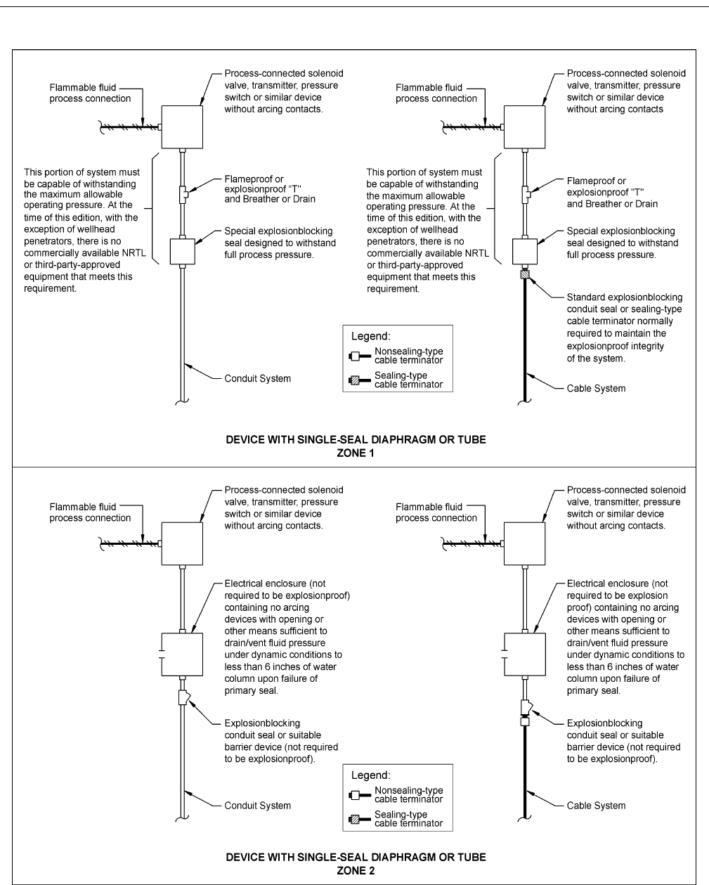
6.8.2.2 Process Instruments
As required by the NEC 501-5 (f)(3), conduit seals or barri-
ers and drains shall be installed in each conduit or cable con-
nection to devices installed on process lines or process vessels
containing flammable fluids and that depend on a single-seal
diaphragm or tube (such as a Bourdon tube or a thermowell) as
a barrier between the process fluid and the conduit or cable.
This is to prevent flammable process fluids from entering con-
duit or cable systems and being transmitted to unclassified
locations or to electrical arcing or high temperature devices in
other portions of the system if the primary seal fails.
a. Draining provisions should be such that process fluid leaks
past the primary seal will be obvious. Conventional conduit
drains and drain seals may not be capable of relieving process
leaks at a rate sufficient to adequately relieve the pressure
generated by primary seal failure to 6 in. of water column
(1493 Pascals).
b. As an alternate secondary sealing method, an approved
assembly consisting of a minimum of 4 feet of Type MI cable
and terminations can be installed between the cable or con-
duit system and single barrier process instruments or devices.
c. The additional seal or barrier and the interconnecting
enclosure or conduit system should meet the temperature and
pressure conditions to which they will be subjected upon fail-
ure of the primary seal. Ordinary conduit seals typically
cannot meet these criteria because of their permissible leakage
rate. Typical examples of such devices are solenoid valves and
level, pressure, temperature and flow switches or transmitters.
This requirement applies even in unclassified locations.
6.8.2.3 Classified Area Boundaries
6.8.2.3.1 Wherever a conduit run passes from a Zone 0
location to a Zone 1 location, from a Zone 1 location to a
Zone 2 location, from a Zone 2 location to an unclassified
location, or any combination thereof, a seal shall be placed in
the conduit run at the boundary, on either side. Except for
approved explosionproof reducers at the conduit seal, the
conduit system shall not contain any union, coupling, box, or
other fitting between the sealing fitting and the point at which
the conduit leaves the Zone 1 or Zone 2 location. An excep-
tion to the above is that unbroken rigid metal conduit that
passes completely through a Zone 1 or a Zone 2 location is
not required to be sealed at the classification boundary if the
termination points of the unbroken conduit are in unclassified
locations and the conduit has no fitting less than 12 in.
beyond each boundary.
44 API RECOMMENDED PRACTICE 14FZ
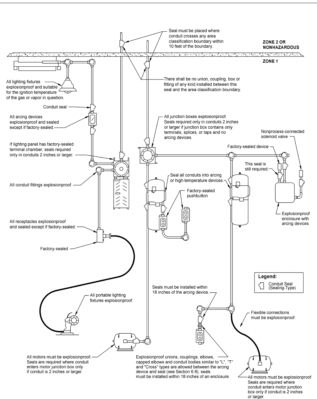
Figure 1—Typical Class I, Zone I Electrical Installation Conduit System Utilizing Class I, Division I Equipment and
Wiring Methods
DESIGN AND INSTALLATION OF ELECTRICAL SYSTEMS FOR FIXED AND FLOATING OFFSHORE PETROLEUM FACILITIES
FOR UNCLASSIFIED AND CLASS I, ZONE 0, ZONE 1, AND ZONE 2 LOCATIONS
45
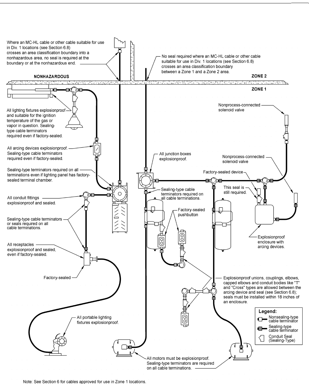
Figure 2—Typical Class I, Zone I Electrical Installation Cable System Utilizing Class I, Division 1 Equipment and
Wiring Methods

46 API RECOMMENDED PRACTICE 14FZ
Figure 3—Typical Class I, Zone 2 Electrical Installation Conduit or Cable System Utilizing Class 1, Division 2
Equipment and Wiring Methods
DESIGN AND INSTALLATION OF ELECTRICAL SYSTEMS FOR FIXED AND FLOATING OFFSHORE PETROLEUM FACILITIES
FOR UNCLASSIFIED AND CLASS I, ZONE 0, ZONE 1, AND ZONE 2 LOCATIONS
47
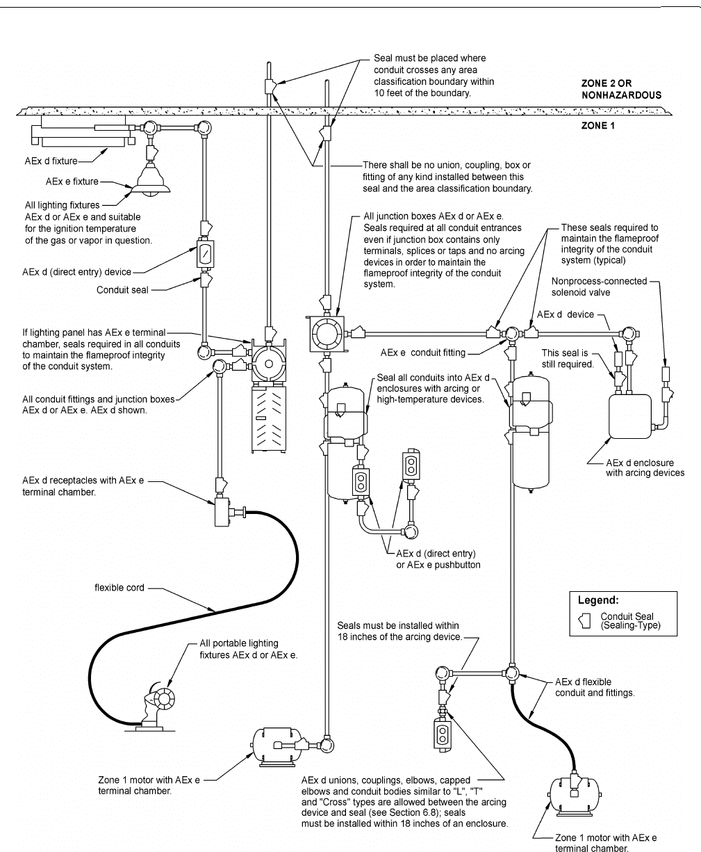
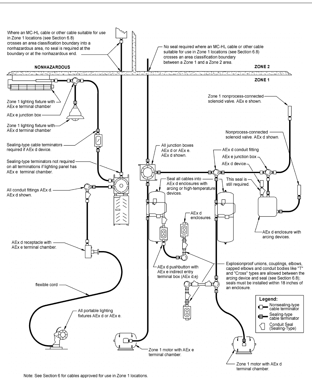
Figure 4—Typical Class I, Zone 1 Electrical Installation Conduit System Utilizing Class I, Zone 1 Equipment and
Wiring Methods
48 API RECOMMENDED PRACTICE 14FZ
Figure 5—Typical Class I, Zone 1 Electrical Installation Cable System Utilizing Class 1, Zone 1 Equipment and Wiring
Methods
DESIGN AND INSTALLATION OF ELECTRICAL SYSTEMS FOR FIXED AND FLOATING OFFSHORE PETROLEUM FACILITIES
FOR UNCLASSIFIED AND CLASS I, ZONE 0, ZONE 1, AND ZONE 2 LOCATIONS
49
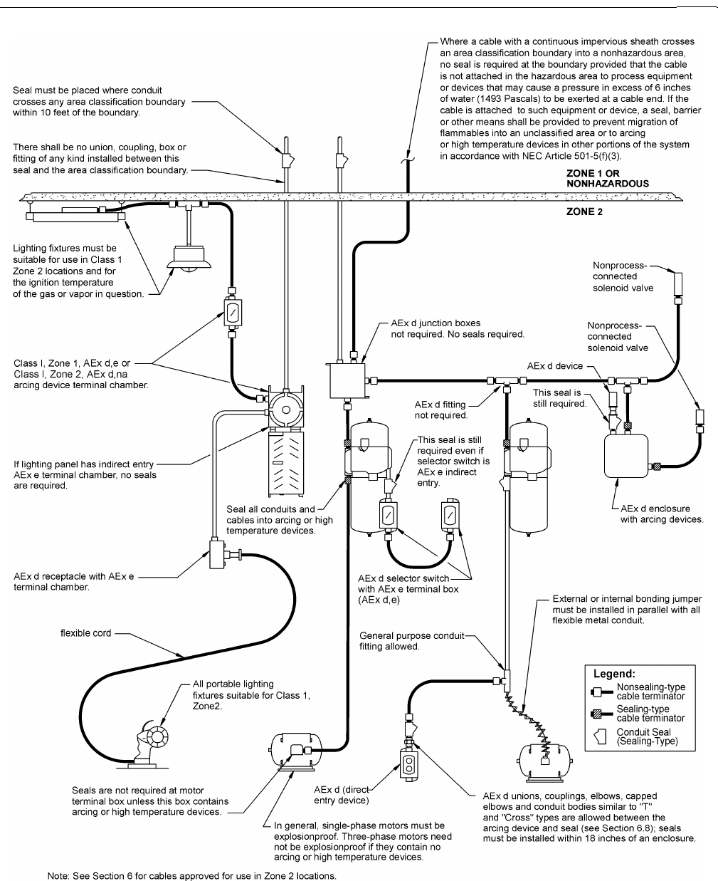
Figure 6—Typical Class I, Zone 2 Electrical Installation Conduit or Cable System Utilizing Class I, Zone 2 Equipment
and Wiring Methods
50 API RECOMMENDED PRACTICE 14FZ
Figure 7—Typical Class I, Zone 1 or Zone 2 Electrical Installation Conduit and Cable Connections to Flammable
Fluid Process-Connected Nonarcing Devices with Single-Seal Diaphragm or Tube