Amano R.S., Sunden B. (Eds.) Computational Fluid Dynamics and Heat Transfer: Emerging Topics
Подождите немного. Документ загружается.

Sunden CH009.tex 25/8/2010 10: 57 Page 336
336 Computational Fluid Dynamics and Heat Transfer
U
y
y
v
y
n
P
n
N
smooth
rough
m
t
= max[0,am(y
*
−y
v
*
)]
y* ≡ y
k
p
/v
m
t
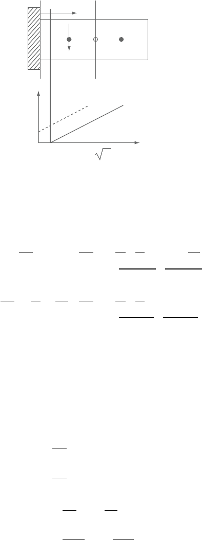
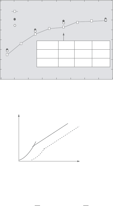
Figure 9.2. Near-wall cells.
In the context of Figure 9.2, the near-wall simplified forms of the momentum
and energy equations become
∂
∂y
∗
(µ + µ
t
)
∂U
∂y
∗
=
ν
2
k
P
∂
∂x
(ρUU) +
∂P
∂x
@
AB C
C
U
(17)
∂
∂y
∗
µ
Pr
+
µ
t
Pr
t
∂
∂y
∗
=
ν
2
k
P
∂
∂x
(ρU ) + S
θ
@
AB C
C
T
(18)
wherePr
t
isaprescribedturbulentPrandtlnumber,takenas0.9.Thefurtherassump-
tionmadeis thatconvectivetransportandthewall-parallelpressure gradient ∂P/∂x
do not change across the wall-adjacent cell which is a standard treatment in the
finite volume method. Thus, the right-hand side (rhs) terms C
U
and C
T
of equa-
tions(17) and(18) canbetreated asconstant.Then, theequations canbeintegrated
analytically over the wall-adjacent cell giving:
if y
∗
< y
∗
v
dU
dy
∗
= (C
U
y
∗
+ A
U
)/µ (19)
d
dy
∗
= Pr(C
T
y
∗
+ A
T
)/µ (20)
U =
C
U
2µ
y
∗2
+
A
U
µ
y
∗
+ B
U
(21)
=
PrC
T
2µ
y
∗2
+
PrA
T
µ
y
∗
+ B
T
(22)
Sunden CH009.tex 25/8/2010 10: 57 Page 337
AWFs of turbulence for complex surface flow phenomena 337
if y
∗
≥y
∗
v
dU
dy
∗
=
C
U
y
∗
+ A
U
µ{1 +α(y
∗
− y
∗
v
)}
(23)
d
dy
∗
=
Pr(C
T
y
∗
+ A
T
)
µ{1 +α
θ
(y
∗
− y
∗
v
)}
(24)
U =
C
U
αµ
y
∗
+
$
A
U
αµ
−
C
U
α
2
µ
(1 −αy
∗
v
)
%
ln[1 + α(y
∗
− y
∗
v
)] +B
U
(25)
=
PrC
T
α
θ
µ
y
∗
(26)
+
=
PrA
T
α
θ
µ
−
PrC
T
α
2
θ
µ
(1 −α
θ
y
∗
v
)
>
ln[1 + α
θ
(y
∗
− y
∗
v
)] +B
T
where α
θ
=αPr/Pr
t
.The integration constants A
U
,B
U
,A
T
,B
T
etc. are deter mined
byapplyingboundaryconditionsat thewall, y
v
andthecellfacepointn.Thevalues
at n are determined by interpolation between the calculated node values at P and
N, whilst at y
v
a monotonic distribution condition is imposed by ensuring that U,
and their gradients should be continuous at y =y
v
. Notice that to determine the
integration constants the empiricallog-law is not referred to at all andtheobtained
logarithmicvelocity equation(25)includes C
U
.The latterimpliesthat the velocity
profile has sensitivity to the pressure gradient since C
U
includes ∂P/∂x.
The result is that the wall shear stress and wall heat flux can be expressed as:
τ
w
= µ
dU
dy
w
= µ
k
1/2
P
ν
dU
dy
∗
w
=
k
1/2
P
A
U
ν
(27)
q
w
=−
ρc
p
ν
Pr
d
dy
w
=−
ρc
p
ν
Pr
k
1/2
P
ν
d
dy
∗
w
=−
ρc
p
k
1/2
P
A
T
µ
(28)
The local generation rate of k, P
k
(=ν
t
(dU/dy)
2
), is written as:
P
k
=
⎧
⎨
⎩
0, if y
∗
< y
∗
v
αk
P
ν
(y
∗
− y
∗
v
)
C
U
y
∗
+ A
U
µ{1 +α(y
∗
− y
∗
v
)}
2
,ify
∗
≥ y
∗
v
(29)
whichcanthenbeintegratedoverthewall-adjacentcelltoproduceanaveragevalue
P
k
for use in solving the k equation of the cell P.
For the dissipation rate ε, the following model is employed:
ε =
=
2νk
P
/y
2
ε
,ify < y
ε
k
1.5
P
/(c
y), if y ≥ y
ε
(30)
Sunden CH009.tex 25/8/2010 10: 57 Page 338
338 Computational Fluid Dynamics and Heat Transfer
Table 9.1. Model coefficients
α c
c
µ
y
∗
vs
y
∗
ε
Pr
∞
t
c
c
µ
2.55 0.09 10.7 5.1 0.9
U
t
n
P
U
n
= (u
n
,v
n
,w
n
)
U
p
= (u
p
,v
p
,w
p
)
y
n
P
y
v
t
n = (n
x
,n
y
,n
z
)
S
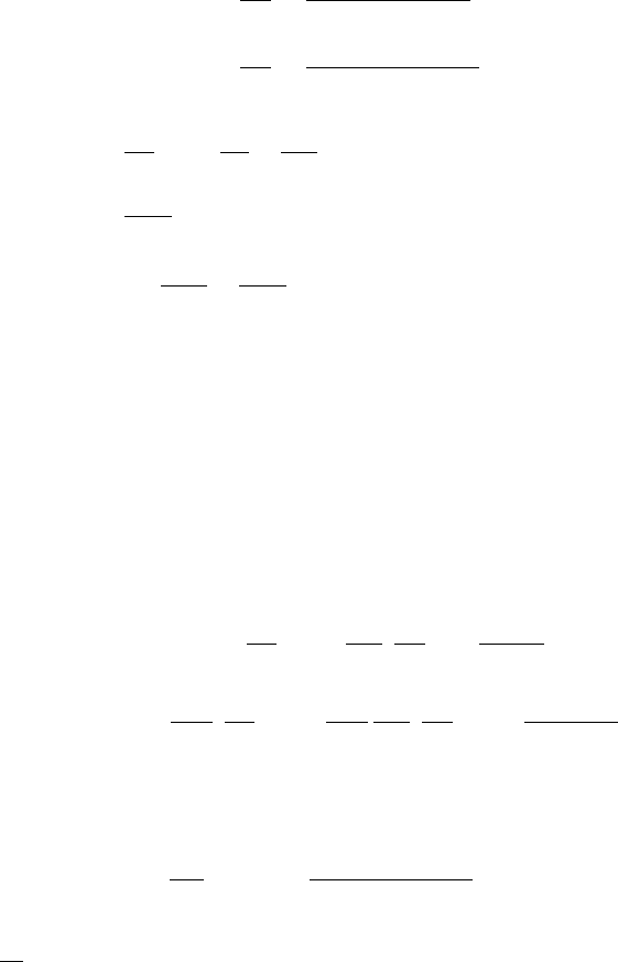
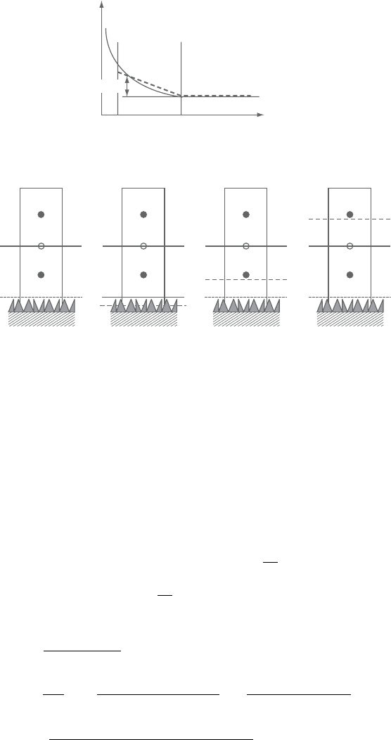
Figure 9.3. Skewed near-wall cells.
The characteristic dissipation scale y
ε
can be defined as y
∗
ε
=2c
to ensure a
continuous variation of ε at y
ε
.Thus, the cell averaged value is obtained as:
ε =
⎧
⎪
⎨
⎪
⎩
2k
2
P
/(νy
∗2
ε
), if y
∗
ε
> y
∗
n
1
y
n
y
ε
2νk
P
y
2
ε
+
&
y
n
y
ε
k
1.5
P
c
y
dy
=
k
2
P
νy
∗
n
2
y
∗
ε
+
1
c
ln
y
∗
n
y
∗
ε
,ify
∗
ε
≤ y
∗
n
(31)
Throughnumericalexperiments,thevalueoftheconstanty
∗
v
wasoptimisedtobe
10.7 which corresponds to approximately half the thickness of the conventionally
defined viscous sub-layer of y
+
=11. The other model coefficients are listed in
Table 9.1.
9.4.2 AWF in non-orthogonal grid systems
In application codes which are written in either structured or unstructured grid
method, the near-wall cells are not always orthogonal to the walls as shown in
Figure9.3.Thus, the way of obtaining the cell face values, U
n
and y
n
, for theAWF
approach is as follows.
When the velocity vector
−→
U
P
at the node P is decomposed to the normal and
tangential directions of the wall, they can be written as:
−→
U
n
P
= (
−→
U
P
·
−→
n )
−→
n (32)
−→
U
t
P
=
−→
U
P
−
−→
U
n
P
(33)
Since the tangential unit vector is obtained as
−→
t =
−→
U
t
P
/|
−→
U
t
P
|, the velocity at the
face n can be obtained as:
U
n
=
−→
t ·
−→
U
n
(34)

Sunden CH009.tex 25/8/2010 10: 57 Page 339
AWFs of turbulence for complex surface flow phenomena 339
Although the distance y
n
of a tetrahedral or pyramidal (triangle in 2D) cell is
determinedasawall-normaldistancefromitsapex,thatofahexahedralorprismatic
(quadrilateral in 2D) cell is obtained by
y
n
= Vol /S (35)
where Vol and S are the volume and the wall area of the cell, respectively.
Whenonecalculatesthevelocitycomponents,thewallshearstressτ
w
−→
t should
be decomposed to each direction.
Examples of applications
AlthoughtheAWFhasshownitssuperbperformanceinmanyflowfields[8,17–19],
the results of a relatively complicated case are shown here.
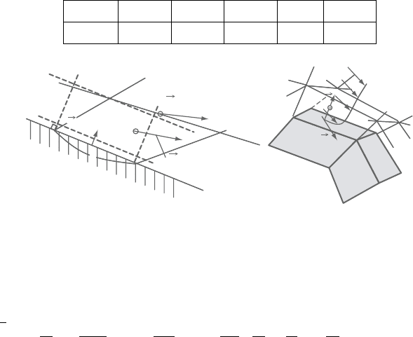
Figure9.4ashowsthegeometryand themeshused foranICEngine port-valve-
cylinderflow [18, 19].The totalcellnumberof300,000 isapplied fora halfmodel.
The flow comes through the intake port and the valve section into the cylinder at
Re10
5
.The turbulence model used is the standard k-ε model.
As shown in Figure 9.4b, it is clear that the standard LWF produces too large
k distribution in the region between the valve and the valve-seat circled by broken
lines.TheAWF,however,reducessuchproductionduetoitsinclusionofthepressure
gradient dependency. This leads to the improved distribution of the gas discharge
coefficientCd by theAWF as shown in Figure 9.5 though it is not very significant.
Thetumbleratio,whichisthemomentumratioofthein-cylinderlongitudinalvortex
and the inlet flow, at the point of 6.8mm of the valveliftisalso better predicted by
theAWF.
9.4.3 AWF for rough wall turbulent flow and heat transfer
In a rough wall turbulent boundary layer, as shown in Figure 9.6, the logarithmic
velocityprofile shiftsdownwarddependingon theequivalent sandgrain roughness
height h and written as an empirical formula [20]:
U
+
=
1
κ
ln
y
+
h
+
+ 8.5 (36)
for completely rough flows.This impliesthat the flow becomes more turbulentdue
to the roughness. It is thus considered that the viscous sub-layer is destroyedinthe
‘fully rough’regime while it partly exists in the ‘transitional roughness’regime.
In common with conventional wall functions (e.g. Cebeci and Bradshaw [21]),
thisextensionoftheAWFstrategy[10]toflowsoverroughsurfacesinvolvestheuse
of the dimensionless roughness height. In this case, however, instead of h
+
, h
∗
is
used to modifythenear-wallvariation oftheturbulent viscosity. More specifically,
in a rough wall turbulence, y
∗
v
is no longer fixed at 10.7 and is modelled to become
smaller. This provides that the modelled distribution of µ
t
shown in Figure 9.2
shifts towards the wall depending on h
∗
. At a certain value of the dimensionless
Sunden CH009.tex 25/8/2010 10: 57 Page 340
340 Computational Fluid Dynamics and Heat Transfer
Standard k-ε + LWF
Standard k-ε + AWF
(b)
(a)
100
90
80
70
60
50
40
30
20
10
0
Figure 9.4. Port-valve-cylinder flow: (a) mesh, (b) k distribution.
roughness height h
∗
=A, y
∗
v
=0 is assumed and at h
∗
> A it is expediently allowed
to have a negative value of y
∗
v
to give a positive value of µ
t
at the wall as:
y
∗
v
= y
∗
vs
{1 −(h
∗
/A)
m
} (37)
wherey
∗
vs
is theviscous sub-layerthickness in thesmooth wallcase.The optimised
valuesforAandm havebeendeterminedthroughaseries ofnumericalexperiments
and comparisons with available flow data. The resultant form is:
y
∗
v
= y
∗
vs
{1 −(h
∗
/70)
m
} (38)
Sunden CH009.tex 25/8/2010 10: 57 Page 341
AWFs of turbulence for complex surface flow phenomena 341
0.8
LDA
LWF
Exp
Cd
Tumble
0.53
1.28
0.577
1.046 0.96
0.589
AWF LWF
AWF
0.7
0.6
0.5
Cd
Discharge coefficient
0.4
0.3
0.2
0.1
0
2.10 3.16 4.21 5.26
Valve lift [mm]
6.31 7.37 8.42 9.47
Figure 9.5. Distribution of gas discharge coefficient.
Smooth
Rough
log (y
+
)
U
+
Figure 9.6. Surface roughness effects on velocity profile.
with
m = max
=
0.5 −0.4
h
∗
70
0.7
,
1 −0.79
h
∗
70
−0.28
>
(39)
For h
∗
< 70, the viscosity-dominated sub-layer exists, but with the above modi-
fied value for y
∗
v
. When h
∗
> 70, corresponding to y
∗
v
< 0, it is totally destroyed.
Note thatalthough the experimentallyknowncondition for thefull rough regime is
h
+
≥70, the condition when the viscous sub-layer vanishes from equation (38) is
h
∗
=70thatcorrespondstoh
+
40inatypicalchannelflowcase.Thisisrathercon-
sistentwiththerelationoftheviscoussub-layerthicknessesinthesmoothwallcase.
(In the smooth wall case, the viscous sub-layer thickness of y
∗
v
=10.7 corresponds
to approximatelyhalf the thickness ofthe conventionally defined viscoussub-layer
of y
+
=11.) It is thus considered that a part of the transitional roughness regime is
somehow effectively modelled into the region without the viscous sub-layer by the
present strategy due to simply assuming the near-wall turbulence behaviour.

Sunden CH009.tex 25/8/2010 10: 57 Page 342
342 Computational Fluid Dynamics and Heat Transfer
Unlikeina sub-layerover a smoothwall, the totalshear stress now includesthe
drag force from the roughness elements in the inner layer which is proportional to
the local velocity squared and becomesdominant away from thewall, compared to
the viscous force. In fact, the data reported byKrogstad et al. [22] andTachie et al.
[23] showed that the turbulent shear stress away from the wall sometimes became
larger than the wall shear stress. This implies that the convective and pressure
gradient contributions shouldberepresented somewhat differentlyacross the inner
layer,belowtheroughnesselementheight.Hence,thepracticeofsimplyevaluating
the rhs of equation (17) in terms of nodal values needs modifying. In the present
strategy a simple approach has been taken by assuming that the total shear stress
remains constant across the roughness element height. Consequently, one is led to
C
U
=
⎧
⎨
⎩
0, if y
∗
≤ h
∗
ν
2
k
P
∂
∂x
(ρUU) +
∂P
∂x
,ify
∗
> h
∗
(40)
Intheenergyequation, Pr
t
isalsonolonger constantoverthewall-adjacentcell.
The reason for this is that since the fluid trapped around the roots of the roughness
elements forms a thermal barrier, the turbulent transport of the thermal energy is
effectively reduced relative to the momentum transport. (The results of the rib-
roughened channel flow direct numerical simulation (DNS) by Nagano et al. [24]
support this consideration since their obtained turbulent Prandtl number increases
significantlytowardsthe wallin the region between the riblets.)Thus, as illustrated
inFigure9.7,althoughitmightbebettertomodelthedistributionofPr
t
withanon-
linearfunction,asimplelinearprofileisassumedintheroughnessregionofy ≤has:
Pr
t
= Pr
∞
t
+ Pr
t
(41)
Pr
t
= C
h
max(0,1− y
∗
/h
∗
) (42)
After a series of numerical experiments referring to the experimental correlation,
the following form for C
h
has beenadoptedwithin the roughness elements(y ≤h):
C
h
=
5.5
1 +(h
∗
/70)
6.5
+ 0.6 (43)
Overthe rest of thefield(y > h), Pr
t
=Pr
∞
t
is applied. (SeeTable 9.1 for themodel
coefficients.)Notethat since the turbulent viscosity is defined as zeroin the region
y < y
v
, the precise profile adopted for the turbulent Prandtl number in the viscous
sub-layer (y < y
v
) does not affect the computation.
At a high Pr flow (Pr>> 1), the sub-layer, across which turbulent transport of
thermal energy is negligible, becomes thinner than the viscous sub-layer. Thus,
the assumption that the turbulent heat flux becomes negligible when y < y
v
no
longer applies. (See the high Pr version of the AWF for such flows presented in
section 9.4.5.)
The analytical solutions of both mean flow and energy equations then can be
obtained in the fourdifferent cases illustrated inFigure 9.8 assuming thatthewall-
adjacent cell height is always greater than the roughness height.Although one can
Sunden CH009.tex 25/8/2010 10: 57 Page 343
AWFs of turbulence for complex surface flow phenomena 343
Pr
t
y*
v
h* y*
Pr
t
∞
∆Pr
t
Figure 9.7. Modelled turbulent Prandtl number distribution.
N
(a)
n
P
h
N
(b)
n
P
h
y
v
y
v
y
v
N
(c)
n
P
h
N
(d)
n
P
h
Figure 9.8. Near-wall cells over a rough wall: (a) y
v
≤0, (b) 0< y
v
≤h,
(c) h < y
v
≤y
n
, (d) y
n
< y
v
.
apply the models of equations (40) and (41) at any node point, limiting them to
the wall-adjacent cells is preferable from the numerical view point since it only
requires a list of the cells facing to walls for wall boundary conditions. (Despite
that, in simple flow cases, the AWF is still applicable to wall-adjacent cells whose
heightislowerthantheroughnessheight[10].)Eveninthecasewithoutanyviscous
sub-layer, case(a) of Figure 9.8a, the resultant expressions for τ
w
and q
w
are of the
same form as those of equations (27) and (28). However, different values of A
U
and A
T
, which are functions of the roughness height, are obtained, corresponding
to the four different cases. (See AppendixA for the detailed derivation process.)
In Table 9.A1, the cell averaged generation term
P
k
and A
U
are listed, intro-
ducing Y
∗
≡1+α(y
∗
−y
∗
v
). Note that equations (30)and (31) are still used forthe
dissipation, and the integration for
P
k
inTable 9.A1 can be performed as follows:
&
b
a
(y − y
v
)
Cy + A
1 +α(y −y
v
)
2
dy
=
C
2
2α
2
y
2
+
C(2A +Cy
v
− 2C/α)
α
2
y +
(A +Cy
v
− C/α)
2
α
2
[1 +α(y −y
v
)]
(44)
+
(A +Cy
v
− C/α)(A +Cy
v
− 3C/α)
α
2
ln[1 + α(y −y
v
)]
b
a
Sunden CH009.tex 25/8/2010 10: 57 Page 344
344 Computational Fluid Dynamics and Heat Transfer
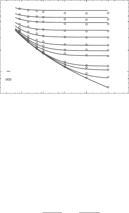
0.01
0.1
1,000 10,000 100,000 1e + 06 1e + 07 1e + 08
f
Re
Moody (1944)
AWF cal.
h/D
5 × 10
−2
3 × 10
−2
2 × 10
−2
1 × 10
−2
5 × 10
−3
2 × 10
−3
1 × 10
−3
5 × 10
−4
1 × 10
−4
5 × 10
−5
1 × 10
−5
0
Figure 9.9. Friction factors in pipe flows (Moody chart).
For heat transfer, the resultant form of the integration constant A
T
can be
written as:
A
T
={µ(
n
−
w
)/Pr +C
T
E
T
}/D
T
(45)
where the coefficients D
T
and E
T
are listed in Table 9.A2, defining α
T
≡
αPr/(Pr
∞
t
), β
T
≡C
0
/(h
∗
Pr
∞
t
), Y
αT
≡1+α
T
(y
∗
−y
∗
v
), Y
βT
≡1+β
T
(y
∗
−y
∗
v
),
and λ
b
≡Y
αT
0
+β
T
h
∗
.
Inthecaseofaconstantwallheatfluxcondition,thewalltemperatureisobtained
by rewriting equations (28) and (45) as:
w
=
n
+
Prq
w
ρc
p
k
1/2
P
D
T
+
PrC
T
E
T
µ
(46)
Examples of applications
The AWF has been implemented with the ‘standard’ linear k-ε (Launder and
Spalding [4], Launder and Sharma: LS [25]) and also with the cubic non-linear
k-ε model of Craft, Launder and Suga: CLS [26]. (Although the LS and the CLS
models are LRN models, with the wall-function grids, the LRN parts of the model
terms do not contribute to the computation results.) For the turbulent heat flux in
thecoreregion,theusualeddydiffusivitymodelwithaprescribedturbulentPrandtl
number Pr
t
=0.9 is used.
Pipe flows. Figure 9.9 compares the predicted friction coefficient and the exper-
imental correlation for turbulent pipe flows, known as the Moody chart [27]. The
turbulence is modelled by the linear k-ε model with the AWF. In the range of
h/D=0 to 0.05 (D: pipe diameter) and Re=8000 to 10
8
, it is confirmed that
the AWF performs reasonably well over a wide range of Reynolds numbers and
roughness heights.
Sunden CH009.tex 25/8/2010 10: 57 Page 345
AWFs of turbulence for complex surface flow phenomena 345
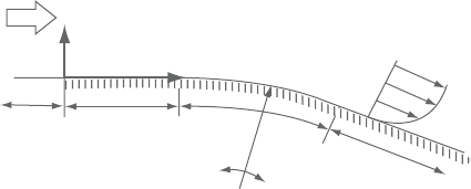
300
398
400
19°
R 1200
160
Air
y
x
Figure 9.10. Flow geometry of the convex rough wall boundary layers of Turner
et al. [28].
Curved wall boundary layer flows. Heat transfer along curved surfaces is very
commonandimportantinengineeringapplicationssuchasinheatsinksandaround
turbineblades.Thus,although theAWFitself doesnotexplicitlyincludesensitivity
tostreamlinecurvature,itisusefultoconfirmitsperformancewhenappliedincom-
bination with a turbulence model which does capture streamline curvature effects.
Hence, the turbulence model used here is the cubic non-linear k-ε model (CLS).
Forcomparison, the roughwallheat transferexperiments over aconvex surface
by Turner et al. [28] are chosen. The flow geometry is shown in Figure 9.10. The
working fluid was air at room temperature and the wall was isothermally heated.
The comparison is made in the cases of trapezoidal-shaped roughness elements.
AccordingtoTurner etal., theequivalentsand grainroughnessheighth is1.1times
the element height. The computational mesh used is 90×20 whose wall adjacent
cell height is 5mm, which is greater than the equivalent sand grain roughness
heights. (A fine mesh of 90×50 whose wall adjacent cell height is 1mm is also
used to confirm the sensitivity to the wall-adjacent cell heights.The corresponding
discussion is addressed in the following paragraph.)
Figure 9.11 compares the heat transfer coefficient α distribution under zero-
pressuregradientconditions. Figure9.11ashowsthecaseofh=0.55mm.Theinlet
velocitiesofU
0
=40,22m/s, respectively, correspondto h
+
90,50 andthusthey
are in the full and the transitional roughness regimes. In the case of h =0.825mm,
shown inFigure9.11b, U
0
=40,22m/s correspond toh
+
135,80 which areboth
in the fully rough regime. From the comparisons, although there can be seen some
discrepancy, it is recognised that the agreement between the experiments and the
predictions is acceptable in both the full and transitional roughness regimes. In
Figure9.11b, theresult by thefine meshof 90×50 whose wall adjacentcell height
is 1mm is also plotted for the case of U
0
=22m/s. It is readily seen that the AWF
is rather insensitive to the near-wall mesh resolution in such a flow case since two
profiles from very different resolutions are nearly the same.
Figure 9.11 also shows the effects of the wall curvature on the heat transfer
coefficients in the case of U
0
=40m/s. (The curved section is in the region of
300mm≤x ≤698mm.) Although the curvature effects observed are not large,
since the curvature is not very strong, they are certainly predicted by the computa-
tions with theAWF and cubic non-linear k-ε model.Turner et al. reported that the
curvatureappearedto causeanincreaseof 2to3%in theheattransfercoefficientα.