ALSTOM T&D. Network Protection And Automation Guide (NPAG)
Подождите немного. Документ загружается.

Chapter 24 The Digital Substation
24-21
Referring again to Figure 24.18, the primary equipment is of
high capital cost, and cannot be de-energised easily – hence it
needs to be left in-service as long as is economically viable.
This period of time can be of the order of 40 years. The
secondary system's life expectancy is often dependent on
advances in technology and increased software-related
functionality being requested, and not due to physical failure or
end-of-life.
Merging units in a process-bus solution can become a
convenient boundary between the two disparate renewal
cycles, such that secondary side retrofits/renewals can be
undertaken without open-circuiting CTs. This mid-life refit can
be done quicker, and more cheaply.
Substation extensions and upgrades can be undertaken as
a software modification:
There is minimal panel hardwiring, hence upgrading is easier,
as a controlled software procedure.
Deploying standard bay solutions capitalises on copycat
scheme roll-out:
As the fundamental scheme performance is defined in
software, if this is standardised, it can be rolled-out in multiple
sites and multiple bays. Standardisation allows the investment
cost in developing the solutions to be amortised over multiple
instances.
Current transformer savings:
A protection scheme is entirely dependent on its input
transducers (typically CTs and VTs) to deliver its performance.
Thus, any lowering of the requirement (size, dimensioning,
accuracy class, number of cores) will mean total scheme cost
savings.
In a process bus scheme, there is minimal or zero physical
burden for the transformers to power – hence sizes and
material costs can be reduced. Merging units can also digitise
the outputs of conventional CTs, close to the CT itself. This
reduces the burden, and hence the CT knee-point voltage
requirement, especially in the case of 5A CT installations.
Configurable (digitised) analogue signal sources for IEDs:
In a process bus solution, there is not the need to switch VT or
CT sources with auxiliary contacts – this can be done as a
“soft” function, rather than requiring make-before-break or
other special auxiliary contact arrangements.
Multipurpose IEDs, not dedicated devices:
The lack of an internal CT in the IEDs means they can perform
both protection and measurement applications. In protection
applications the dynamic range to measure fault current
magnitudes is required, and in measurement applications
accuracy is the key.
24.6 CONCLUSION
IEC61850-9.2, and IEC61850 in general are at the heart of the
digital substation. Together they have revolutionised
substation engineering. This chapter has aimed to equip
engineers with an understanding of the terminology and
concepts in order to be able to function in this new world
focused on Ethernet communication technology.
24.7 REFERENCES
[24.1] Shannon, C. E., & Weaver, W. (1949). The
mathematical theory of communication. Urbana,
Illinois: University of Illinois Press.
[24.2] Reece, I. and Walker, S. (1997) Teaching, Training and
Learning. Sunderland: Business Education Publishers
Ltd.
© 2011 Alstom Grid. Single copies of this document may be filed or printed for personal non-commercial use and must include this
copyright notice but may not be copied or displayed for commercial purposes without the prior written permission of Alstom Grid.
© 2011 Alstom Grid. Single copies of this document may be filed or printed for personal non-commercial use and must include this
copyright notice but may not be copied or displayed for commercial purposes without the prior written permission of Alstom Grid.
25-1
Chapter 25
Substation Control and Automation
25.1 Introduction
25.2 Topology and Functionality
25.3 Hardware Implementation
25.4 Substation Automation Functionality
25.5 System Configuration and Testing
25.1 INTRODUCTION
The complex interlocking and sequence control requirements
that prevail in most substations of any significant size lend
themselves naturally to the application of substation
automation. These requirements can be readily expressed in
mathematical logic (such as truth tables and Boolean algebra)
and thus ease the application of computers and associated
software. Hence, computers have been applied to the control
of electrical networks for many years, and examples of them
being applied to substation control/automation were in use in
the early 1970’s. The first applications were naturally in the
bulk power transmission field, as a natural extension of a trend
to centralised control rooms for such systems. The large
capital investment in such systems and the consequences of
major system disruption made the cost of such schemes
justifiable. In the last twenty years or so, continuing cost
pressures on utilities and advances in digital hardware have led
to the application of computers to substation control and
automation as a first-choice solution.
25.2 TOPOLOGY AND FUNCTIONALITY
The topology of a substation control system is the architecture
of the digital system used. The functionality of such a system
is the complete set of functions that can be implemented in the
control system – noting that a particular substation may only
utilise a subset of the functionality possible.
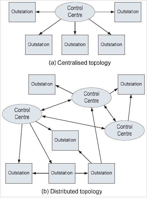
All digital control systems utilise one of two basic topologies,
the basic concepts of which are illustrated in Figure 25.1:
x centralised
x distributed
Early examples of substation automation used the centrali
sed
concept, due to limitations in technology, both of processor
power and communication techniques. Latest examples use a
distributed architecture, in that a number of Intelligent
Electronic Devices (IEDs), such as numerical relays, may be
linked to a local processor. The local processor may control
one or more bays in a substation. All of the local processors
are, in turn, connected to a Human Machine Interface (or
HMI), and possibly also to a local or remote SCADA system for
overall network monitoring/control.
© 2011 Alstom Grid. Single copies of this document may be filed or printed for personal non-commercial use and must include this
copyright notice but may not be copied or displayed for commercial purposes without the prior written permission of Alstom Grid.
Network Protection & Automation Guide
25-2
Figure 25.1: Basic substation automation system topologies
25.2.1 System Elements
The main system elements in a substation control system are:
x IEDs, implementing a specific function or functions on
a circuit or busbar in a substation. The most common
example of an IED is a n
umerical protection relay, but it
could also be a measurement device, interface unit to
older relays, etc.
x Bay Module (or “Bay Controller”). This device will
normally contain all of the software required for the
control and interlocking of a single bay in the
substation, an
d sufficient I/O to interface to all of the
devices required for measurement/protection/control of
the bay. The I/O may include digital and analogue I/O
(for interfacing to discrete devices such as breaker
tripping and closing circuits, isolator motors, non-digital
legacy relays) and communications links to IEDs.
x RTU (Remote Terminal Unit). This is a device installed
at a substation, which collects analogue, digital and
status data and transmits this in a
suitable format to
the remote SCADA master.
x Human Machine Interface (HMI). This is the principal
user interface and would normally take the form of a
computer. A desktop PC is commonly used, but
specialised computers are al
so possible, while normally
unmanned substations may dispense with a
permanently installed HMI and rely on
operations/maintenance staff bringing a laptop
computer equipped with the appropriate software with
them when attendance is required. Sometimes, one or
more printers are linked to the HMI in order to provide
hard-copy event records or other reports.
x A communications bus or busses, linking the various
devices. Where a substation automation system is
being retrofitted to an existing substation, it may be
necessary to use existing communications busses to
communicate with some legacy devices. This can lead
to a multiplicity of communications busses and
protoc
ols within the automation system
x A link to a remote SCADA system. This may be
provided by a dedicated interface unit, be part of the
HMI computer or part of an IED. A dedicated gatew
ay
is used to provide a secure means of communicating
outside the substation, encrypting the data and making
it immune from cyber attacks.
25.2.2 System Requirements
A substation control/automation scheme will normally be
required to possess the following features:
x control of all substation electrical equipment from a
central point
x monitoring of all substation electrical equipment from a
central point
x interface to remote SCADA system
x control of electrical equipment in a bay locally
x monitoring of electrical equipment in a bay locally
x status monitoring of all connected substation
automation equipment
x system database management
x energy management
x condition monitoring of substation electrical equipment
(switchgear, transformers, relays, etc.)
The system may be required to be fault-toler
ant, implying that
redundancy in devices and communications paths is provided.
The extent of fault-tolerance provided will depend on the size
and criticality of the substation to the operator, and the normal
manning status (ie. whether manned or unmanned). Many of
the functions may be executed from a remote location, such as
a Regional or National Control Centre, in addition to the
substation itself.
Certain of the above functions will be required even in the
© 2011 Alstom Grid. Single copies of this document may be filed or printed for personal non-commercial use and must include this
copyright notice but may not be copied or displayed for commercial purposes without the prior written permission of Alstom Grid.
Chapter 25 Substation Control and Automation
25-3
most elementary application. However, the selection of the
complete set of functions required for a particular application is
essentially the responsibility of the end-user Utility. Due to a
modular, ‘building block’ approach to software design, it is
normally relatively easy to add functionality at a later stage.
This often occurs through changing operators’ needs and/or
electrical network development. Compatibility of the
underlying database of network data must be addressed to
ensure historical data can still be accessed.
25.3 HARDWARE IMPLEMENTATION
To form a digital substation control system (DCS), the various
elements described above must be assembled into some form
of topology. Three major hardware topologies can be identified
as being commonly used, as follows:
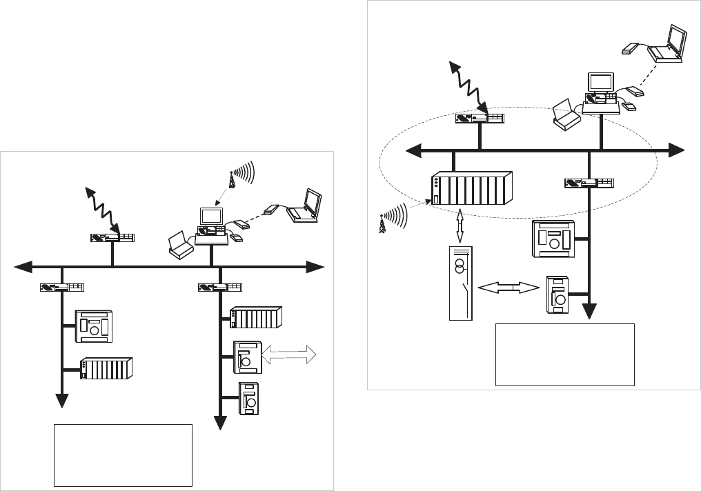
25.3.1 HMI-based Topology
This takes the form of Figure 25.2. The software to implement
the control/automation functions resides in the HMI computer
and this has direct links to IEDs using one or more
communications protocols. The link to a remote SCADA
system is normally also provided in the HMI computer, though
a separate interface unit may be provided to offload some of
the processor requirements from the HMI computer, especially
if a proprietary communications protocol to the SCADA system
is used.
Bus interface
Internet
or PSTN
Master clock
(GPS, radio)
Remote
HMI
HMI
Telecontrol or
Bus interface
Station bus
Bus interface
Legacy bus
IEDs
Computer
Legacy bus
IEDs
Computer
I
/
O
,
d
e
v
i
c
e
s
CT, VT
SCADA
interface
The HMI, telecontrol interface
and the bus interface could be
separate equipment or
integrated into the same device
Figure 25.2: HMI-based hardware topology
For this topology, a powerful HMI computer is clearly required
if large numbers of IEDs are to be accommodated. In practice,
costs usually dictate the use of a standard PC, and hence there
will be limitations on substation size that it can be applied to
because of a resulting limit to the number of IEDs that can be
connected. The other important issue is one of reliability and
availability – there is only one computer that can control the
substation and therefore only local manual control will be
possible if the computer fails for any reason. Such a topology
is therefore only suited to small MV substations where the
consequences of computer failure (requiring a visit from a
repair crew to remedy) are acceptable. Bay Modules are not
used, the software for control and interlocking of each
substation bay runs as part of the HMI computer software.
25.3.2 RTU-based Topology
This topology is an enhancement of the HMI topology and is
shown in Figure 25.3. A digital RTU is used to host the
automation software, freeing the HMI computer for operator
interface duties only. The HMI computer can therefore be less
powerful and usually takes the form of a standard PC, or for
unmanned substations, visiting personnel can use a laptop PC.
Bus interface
I
n
t
e
r
n
e
t
o
r
P
S
T
N
M
a
s
t
e
r
c
l
o
c
k
(
G
P
S
,r
a
d
io
)
Remote
HMI
HMI
Telecontrol or
Bus interface
RTU
Legacy bus
IEDs
I/O, devices
CT, VT
SCADA
interface
The RTU, telecontrol interface
and the bus interface could be
separate equipment or
integrated into the same device
Figure 25.3: RTU-based topology
A greater number of I/O points can be accommodated than in
the HMI topology, while the possibility exists of hosting a wider
variety of communications protocols for IEDs and the remote
SCADA connection. Bay Modules are not required, the
associated software for interlocking and control sequences is
part of the RTU software.
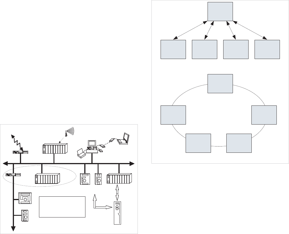
25.3.3 Decentralised Topology
This topology is illustrated in Figure 25.4. In it, each bay of the
© 2011 Alstom Grid. Single copies of this document may be filed or printed for personal non-commercial use and must include this
copyright notice but may not be copied or displayed for commercial purposes without the prior written permission of Alstom Grid.
Network Protection & Automation Guide
25-4
substation is controlled by a Bay Module (alternatively
commonly described as a Bay Controller). This device houses
the control and interlocking software, interfaces to the various
IEDs required as part of the control and protection for the bay,
and interfaces to the HMI. It is possible to use an HMI
computer to take local control of an individual bay for
commissioning/testing and fault finding purposes. The
amount of data from the various substation I/O points dictates
that a separate SCADA interface unit is provided (often called
an RTU or Gateway), while it is possible to have more than one
HMI computer, the primary one being dedicated to operations
and others for engineering use. Optionally, a remote HMI
computer may be made available via a separate link. It is
always desirable in such schemes to separate the real-time
operations function from engineering tasks, which do not have
the same time-critical importance.
Internet
or PSTN
Master clock
(GPS, radio)
Remote
HMI
HMI
Telecontrol
i
nt
er
f
ac
e
Bay Module
Legacy bus
IED's
I/O, devices
CT, VT
SCADA
interface
Bay Module
Computer
Station bus
IED's
Bus interface
The bay module and bus
interface could be separate
equipment or integrated into the
same device
Figure 25.4: Decentralised topology
The connection between the various Bay Modules and the
HMI computer is of some interest. Simplest is the star
arrangement of Figure 25.5(a). This is the least-cost solution
but suffers from two disadvantages. Firstly, a break in the link
will result in loss of remote control of the bay affected; only
local control via a local HMI computer connected to the bay is
then possible. Secondly, the number of communications ports
available on the HMI computer will limit the number of Bay
Modules.
Central
computer
Bay
module
Bay
module
Bay
module
Bay
module
(a) Star connection of bay modules
Bay
module
Bay
module
Bay
module
Bay
module
Bay
module
(b) Ring connection of bay modules
Figure 25.5: Methods of hardware interconnection
Of course, it is possible to overcome the first problem by
duplicating links and running the links in physically separate
routes.
An alternative is to connect the Bay Modules, HMI computer
and SCADA gateway in a ring, as shown in Figure 25.5(b). By
using a communications architecture such as found in a LAN
network, each device is able to talk to any other device on the
ring without any message conflicts. A single break in the ring
does not result in loss of any facilities. The detection of ring
breakage and re-configuration required can be made
automatically. Thus, the availability and fault tolerance of the
network is improved. Multiple rings emanating from the HMI
computer can be used if the number of devices exceeds the
limit for a single ring. It can be easier to install on a step-by-
step basis for retrofit applications, but of course, all these
advantages have a downside. The cost of such a topology is
higher than that of the other solutions, so this topology is
reserved for situations where the highest reliability and
availability are required.
It is usual to have more than one operators’ HMI, either for
operational reasons or for fault-tolerance. The system
computer may be duplicated on a ‘hot-standby’ or ‘dual-
redundant’ basis, or tasks may be normally shared between
two or more system computers with each of them having the
capability of taking over the functions of one of the others in
the event of a failure.
The total I/O count in a major substation will become large
© 2011 Alstom Grid. Single copies of this document may be filed or printed for personal non-commercial use and must include this
copyright notice but may not be copied or displayed for commercial purposes without the prior written permission of Alstom Grid.

Chapter 25 Substation Control and Automation
25-5
and it must be ensured that the computer hardware and
communications links have sufficient performance to ensure
prompt processing of incoming data. Overload in this area can
lead to one or more of the following:
x undue delay in updating the system status
diagrams/events log/alarm log in response to an
incident
x corrupti
on of system database, so that the information
presented to the operator is not an accurate
representation of the state of the actual electrical
system
x system lockup
As I/O at the bay level, both digital and analogue will typically
be handled by intelligent relays or specialised IEDs, it is
therefore important to ensure that these d
evices have sufficient
I/O capacity. If additional IEDs have to be provided solely for
ensuring adequate I/O capacity, cost and space requirements
will increase. There will also be an increase in the number of
communications links required.
25.4 SUBSTATION AUTOMATION
FUNCTIONALITY
The hardware implementation provides the physical means to
implement the functionality of the substation automation
scheme. The software provided in the various devices is used
to implement the functionality required. The software may be
quite simple or extremely complex – Table 25.1 illustrates the
functionality that may be provided in a large scheme.
The description of the electrical network and the characteristics
of the various devices associated with the network are held
within the computer as a database or set of databases. Within
each database, data is organised into tables, usually on a ‘per
device’ basis that reflects the important characteristics of the
device and its interrelationship with other devices on the
network. Electrical system configuration changes require
modification of the database using an appropriate software
tool. The tool is normally a high level, user-friendly interface,
so that modifications to the one-line can be drawn directly on-
screen, with ‘pick-and–place’ facilities. This work would
normally be done offline on the Engineers’ workstation, if
available, or as a background task on the control computer if
not. Careful and extensive checking of the data is required,
both before and after entry into the database, to ensure that no
errors have been made. Full testing on the new configuration
using a simulator is recommended prior to use of the new
database on the main control computer to ensure that there is
minimal possibility of errors.
The software is written as a set of well-proven, standard
modules, so there is little or no need for new modules to be
written and tested for a particular substation. The required
data for the calculations performed by the software is held in
the network database. This means that adding functionality
later is not difficult, so long as the database design has
considered this possibility. There may be problems if the
electrical system configuration is altered or additional
functionality added, in reading historical data prior to the
change. Training of operations personnel will inevitably be
required in operation of the system, configuration
management and automation system maintenance.
Automation system suppliers will be able to provide
configuration management and system maintenance services
under contract if required, often with defined cost schedules
and response times so financial management of the
automation scheme once installed is well-defined.
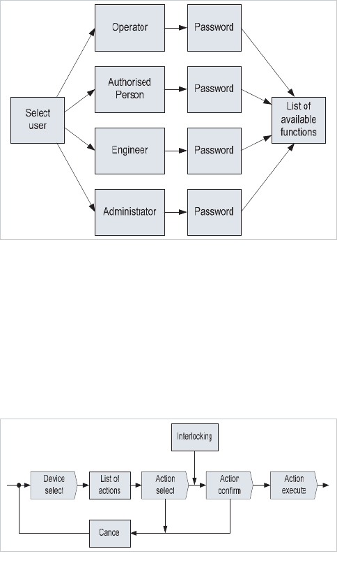
The issuing of commands to switching devices in the system
has to be carefully structured, in order to prevent commands
that would cause a hazard being issued. A hierarchical
structure is commonly used as shown in Figure 25.6,
beginning with the requirement for an operator wishing to
issue a command to switching devices to log-in to the system
using a password, or other means of authentication.
Functional area
Interlocking CB's Isolators Contactors
Tripping sequences CB failure Intertripping Simultaneous trips
Switching sequences Automatic transformer changeover Automatic busbar changeover Restoration of supply following faul
t
Network re-configuration
Load managemen
t
Load shedding Load restoration Generator despatch
Transformer supervision OLTC control Load managemen
t
Energy monitoring Import/export control Energy managemen
t
Power factor control
Switchgear monitoring AIS monitoring GIS monitoring
Equipment status Relay status CB status Isolator status
Parameter setting Relays Transformers Switching sequences IED configuration
HMI functionality
Access control One-line views System views Event logging
HMI functionality
Trend curves Harmonic analysis Remote access Disturbance analysis
HMI functionality
Interface to SCADA Alarm processing
Functionality
Table 2
5
.
1
: Typical substation automation functionalit
y
© 2011 Alstom Grid. Single copies of this document may be filed or printed for personal non-commercial use and must include this
copyright notice but may not be copied or displayed for commercial purposes without the prior written permission of Alstom Grid.
Network Protection & Automation Guide
25-6
Figure 25.6 Hierarchical command structure
Different levels of authority, allowing for restrictions on the
type and/or location of switching commands capable of being
issued by a particular operator may be implemented at this
stage – this is termed as ‘role-based access’. The next level in
the hierarchy is to structure the issuing of commands on an
‘issue/confirm/execute’ basis (Figure 25.7), so that the
operator is given an opportunity to check that the command
entered is correct prior to its execution.
Figure 25.7: Device selection/operation
The final level in the hierarchy is implemented in software at
the bay level and is actioned after the operator confirms that
the switching action is to be executed. At this stage, prior to
execution, the operation is checked against:
x devices locked out - i.e. prevented from operation
x interlocking of devices/switching sequences
to ensure that the command issued is safe to carry out. The
action is cancelled and the operator informed if it is not sa
fe to
proceed, otherwise the action is executed and the operator
informed when it is complete.
In a number of systems, some routine switching operations
(e.g. transfer of a feeder from one busbar to the other in a
double-bus substation) are automated in software. The
operator need only request the ‘bus-transfer’ action to be
carried out on a particular feeder, and the software is able to
work out the correct switching sequence required. This
minimises the possibility of operator error, but at the expense
of some extra complexity in the software and more extensive
checking at the factory test stage. However, since software is
modular in nature, substation electrical topology is restricted to
a number of standard configurations and such sequences are
common, the software development is essentially a one-off
activity for any particular substation control system. The
development cost can be spread over the sale of a number of
such systems, and hence the cost to any individual user is
small compared with the potential benefits.
25.5 SYSTEM CONFIGURATION AND TESTING
These tasks, along with project management, are the most
time consuming tasks in the process of realising a control and
monitoring system for an electrical network. The strategies
available for dealing with these problems vary between
manufacturers, but typical approaches are as follows.
25.5.1 System Configuration
Software tools exist that assist in configuring a modern
substation or network automation system. The extent to
which the task is automated will vary, but all require as a
minimum the details of the network to be controlled, extending
to the individual device level (circuit breaker, isolator,
disconnector, etc.). Where communication to an existing
SCADA system is required, data on the logical addresses
expected by the SCADA system and devices controlled
remotely from the SCADA system will also be part of the data
input. Use can also be made of existing databases that cover
pre-defined network configurations – for example the
interlocking equations for a substation bay.
Software tools will check the data for consistency, prior to
creation of:
x the required equipment that forms the automation
scheme, together with the required interconnections
x the databases for each individual device
x The data will divided into dom
ains, according to the use
made of the data:
x process – CB/isolator position, interlocking equation,
values of current/voltage
x system – number of bay computers, hardware
configuration of each bay computer, automated
sequences
x graphical – the links between each mimic display and
the data to be displayed
x operator – security access levels, alarm texts
, etc.
x external constraints – data addresses for external
database access
Once all the data has been de
fined, the configurator tools can
© 2011 Alstom Grid. Single copies of this document may be filed or printed for personal non-commercial use and must include this
copyright notice but may not be copied or displayed for commercial purposes without the prior written permission of Alstom Grid.
Chapter 25 Substation Control and Automation
25-7
define the hardware configuration to provide the required
functions at least cost, and the data required for
implementation of the automation scheme.
25.5.2 System Testing
The degree of testing to be carried will be defined by the
customer and encapsulated in a specification for system
testing. It is normal for testing of the complete functionality of
the scheme to be required prior to despatch from the
manufacturer – termed a ‘factory acceptance test’ (FAT). The
larger and more complex the automation scheme, the more
important for all parties that such FAT testing is carried out. It
is accepted wisdom that the earlier problems are discovered,
the cheaper and quicker it is to fix them. Remediation of
problems on-site during commissioning is the most expensive
and time-consuming activity. Manual testing of a network
automation scheme is only practical for small networks, due to
the cost of testing. Simulation tools are necessary for all other
automation schemes. These tools fall into two categories:
x simulator tools that re-create the network to be
controlled by the automation system.
x test management tools
25.5.2.1 Simulator tools
Simulator tools are dedicated to the network being tested.
They will normally be provided with a simulation language that
the test team can use to play scenarios, and hence determine
how the automation system will react to various stimuli.
Process simulator tools may be hardware and/or software
based and emulate the response of the various devices to be
controlled or measured (breakers, isolators, instrument
transformers or protection relays). They must be capable of
closely following the dynamic response of such devices under
multiple and cascade simulation scenarios. Specific tools and
libraries are developed as required, which simulate the
response of equipment within the control span of the
automation equipment, or that of equipment outside of the
span of control, in order that the response of the automation
system can be tested.
Communications simulator tools are used both to load the
internal communications network within the automation
system to ensure that all devices are communicating correctly
and that performance of the overall automation system is
within specification during periods of high communications
traffic loading. These simulators are standardised and a single
simulator may be able to emulate several items of equipment.
External communications simulators test the communications
with an external system, such as a remote control centre.
25.5.3 Test Strategy
The strategy adopted for the testing of the automation system
must naturally satisfy client requirements, and generally
follows on of two approaches:
x a single test is carried out when all equipment for the
scheme has been assembled
x incremental tests are carried out as the automation
system is built up, with simulators used to represent
missing equipment
The former solution is quickest and cheapest, but can give rise
to problems wh
ere it is not easy to locate problems down to
the device level. It is therefore used principally when an
upgrade to an existing system is being carried out.
It is usual for all of the functionality to be tested, including that
specified for normal conditions and specified levels of
degradation within the automation system. This leads to a
large number of tests being required.
25.5.4 Management of System Tests
The large number of tests required to demonstrate the
compliance of an automation system with specification makes
manual techniques for management of the tests cumbersome
and time consuming. The end result is increased cost and
timescale. Moreover, each test may result in a large amount
of data to be analysed. The results of the analysis need to be
presented in an easily understood form and stored as quality
records, for traceability. If changes are made to software for
any reason over the lifetime of the equipment, the different
versions must be stored, together with a record of what the
changes between versions were, and why they were made.
The management of this becomes very complex, and software
tools are normally used to address the issues of test schedules,
test result presentation, software version control, and
configuration management.
© 2011 Alstom Grid. Single copies of this document may be filed or printed for personal non-commercial use and must include this
copyright notice but may not be copied or displayed for commercial purposes without the prior written permission of Alstom Grid.
© 2011 Alstom Grid. Single copies of this document may be filed or printed for personal non-commercial use and must include this
copyright notice but may not be copied or displayed for commercial purposes without the prior written permission of Alstom Grid.
