ALSTOM T&D. Network Protection And Automation Guide (NPAG)
Подождите немного. Документ загружается.

Chapter 22 Power System Measurements
22-9
installed, together with suitable switching arrangements in the
signal input/output circuits so that a single device may be
selected to cover several CBs.
22.8.2 Auto-synchroniser
An auto-synchroniser contains additional functionality
compared to a check synchroniser. When an auto-
synchroniser is placed in service, it measures the frequency
and magnitude of the voltages on both sides of the circuit
breaker, and automatically adjusts one of the voltages if
conditions are not correct. Application of auto-synchronisers is
normally restricted to generators – i.e. the situation shown in
Figure 22.4(a), replacing the check synchroniser with an auto-
synchroniser. This is because it is generally not possible to
adjust either of the network voltages by changing the settings
of one or a very few equipments in a network. When applied
to a generator, it is relatively easy to adjust the frequency and
magnitude of the generated voltage by transmitting signals to
the Governor and AVR respectively.
The auto-synchroniser will check the voltage of the incoming
generator against the network voltage for compliance with the
following:
a. slip frequency within limits (i.e. difference in
frequency between the generator and network)
b. phase difference between the voltages within limits
c. voltage magnitude difference within limits
The CB close command is issued automatically when all three
conditions are satisfied. Checks may also be made that the
network frequency and voltage is within pre-set limits, and if
not the synchronising sequence is locked out. This prevents
synchronising under unusual network conditions, when it may
not be desirable. This facility should be used with caution,
since under some emergency conditions, it could block the
synchronising of a generator that was urgently required in
service to help assist in overcoming the condition.
If (a) above is not within limits, signals are sent automatically
to the governor of the generating set to adjust the speed
setpoint appropriately. In the case of (c) not in limits, similar
signals are sent to the Automatic Voltage Regulator to raise or
lower the setpoint. The signals are commonly in the form of
pulses to raise or lower the setpoint, but could be continuous
signals if that is what the particular equipment requires. It is
normal for the speed and voltage of the generator to be slightly
higher than that of the network, and this can be
accommodated either by initial settings on the Governor/AVR
or by providing setpoint values in the synchroniser. This
ensures stable synchronising and export of power at lagging
power factor to the network by the generator after CB closure.
The possibility of tripping due to reverse/low forward power
conditions and/or field failure/under-excitation is avoided. Use
of an auto-synchroniser also helps avoid human error if
manual synchronising were employed – there is potential for
damage to equipment, primarily the generator, if synchronising
outside of permitted limits occurs.
To ensure that the CB is closed at the correct instant, the CB
close time is normally a required data item. The auto-
synchroniser calculates from a knowledge of this and the slip
frequency the correct time in advance of phase co-incidence to
issue the CB close command. This ensures that the CB closes
as close to the instant of phase co-incidence as possible. Upon
receipt of the signal indicating ‘CB closed’ a further signal to
raise frequency may be sent to the governor to ensure stable
export of power is achieved. Conversely, failure of the CB to
close within a set time period will reset the auto-synchroniser,
ready for another attempt, and if further attempts are still
unsuccessful, the auto-synchroniser will lock out and raise an
alarm.
Practice in respect of fitting of auto-synchronisers varies widely
between Utilities. Where policy is flexible, it is most common
when the time to synchronise is important – i.e. emergency
standby and peak lopping sets. Many Utilities still relay on
manual synchronising procedures. It is also possible for both
an auto-synchroniser and check-synchroniser to be fitted in
series. This provides protection against internal failure of the
auto-synchroniser leading to a CB close command being given
incorrectly.
22.9 DISTURBANCE RECORDERS
Power systems suffer from various types of disturbances. In
post-fault analysis, it is beneficial to have a detailed record of a
disturbance to enable the initiating event to be distinguished
from the subsequent effects. Especially where the disturbance
causes further problems (e.g. single-phase fault develops into
3-phase), a detailed recording of the fault may be required to
distinguish between cause and effect. If the effects of a fault
are spread over a wide area, records of the disturbance from a
number of locations can assist in determining the location of
the disturbance. The equipment used for this purpose is
known as a disturbance, or fault, recorder.
22.9.1 Disturbance Recorder Features
A disturbance recorder will normally have the following
capabilities:
x multi-channel analogue input waveform recording
x multi-channel digital input recording
© 2011 Alstom Grid. Single copies of this document may be filed or printed for personal non-commercial use and must include this
copyright notice but may not be copied or displayed for commercial purposes without the prior written permission of Alstom Grid.
Network Protection & Automation Guide
22-10
x storage of several fault records, ready for
download/analysis
x recording time of several seconds per disturbance
x triggering from any analogue or digital input channel,
or quantity derived from a combination of inputs, or
manually
x distance to fault location for one or more feeders
x variable pre/post trigger recording length
x time synchronisation (IRIG-B, GPS, etc.)
x programmable sampling rates
x standard data transfer formats (IEEE COMTRADE (IEC
60255-24), etc.
x communication links to control centre (Ethernet,
modem, etc.)
x self-monitoring/diagnostics
Analogue channels are provided to record the important
currents and voltages at the fault recorder location. High
resolution is
required to ensure accurate capture of the
waveforms, with 16 bit A/D conversion being usual. Digital
inputs are provided to capture signals such as CB opening,
protection relay operation, intertrip signals, etc. so that a
complete picture of the sequence of events can be built up.
The information can then be used to check that the sequence
of operations post-fault is correct, or assist in determining the
cause of an unexpected sequence of operations. To avoid loss
of the disturbance data, sufficient memory is provided to
capture and store the data from several faults prior to transfer
of the data for analysis. Flexibility in the triggering
arrangements is extremely important, as it is pointless to
install a disturbance recorder, only for it to miss recording
events due to lack of appropriate triggering facilities. It is
normal for triggering to be available if the relevant threshold is
crossed on any analogue or digital channel, or a quantity
derived from a combination of the inputs.
Power system disturbances may last from periods of a few
seconds to several minutes. To ensure that maximum benefit
is obtained from the investment, a disturbance recorder must
be able to capture events over a wide range of timescales. This
leads to the provision of programmable sampling rates, to
ensure that short-term transients are captured with sufficient
resolution while also ensuring that longer-term ones have
sufficient of the transient captured to enable a meaningful
analysis to be undertaken. The record for each disturbance is
divided into sections covering pre-fault, fault, and post–fault
periods, and each of these periods may have different sampling
rates. Time synchronisation is also a vital feature, to enable a
recording from one recorder to be aligned with another of the
same event from a different recorder to obtain a complete
picture of events.
Since most disturbance recorders are fitted in substations that
are normally unmanned, the provision to download captured
information is essential. Each fault recording will contain a
large amount of data, and it is vital that the data is uniquely
identified in respect of recorder, fault event, channel, etc.
Standards exist in field to facilitate the interchange of data, of
which perhaps the best known is the IEEE COMTRADE
format, now also an international standard (IEC 60255-24).
Once downloaded, the data from a disturbance recorder can
be analysed by various PC software packages. The software
will often have the ability to perform harmonic and other
analysis.
© 2011 Alstom Grid. Single copies of this document may be filed or printed for personal non-commercial use and must include this
copyright notice but may not be copied or displayed for commercial purposes without the prior written permission of Alstom Grid.
Chapter 22 Power System Measurements
22-11
© 2011 Alstom Grid. Single copies of this document may be filed or printed for personal non-commercial use and must include this
copyright notice but may not be copied or displayed for commercial purposes without the prior written permission of Alstom Grid.
© 2011 Alstom Grid. Single copies of this document may be filed or printed for personal non-commercial use and must include this
copyright notice but may not be copied or displayed for commercial purposes without the prior written permission of Alstom Grid.
Alstom Grid 23-1
Chapter 23
Power Quality
23.1 Introduction
23.2 Classification of Power System Disturbances
23.3 Causes and Impact of Power quality Problems
23.1 INTRODUCTION
Over the last forty years or so, the amount of equipment
containing electronics has increased dramatically. Such
equipment can both cause and be affected by electromagnetic
disturbances. A disturbance that affects a process control
computer in a large industrial complex could easily result in
shutdown of the process. The lost production and product
recycling during start-up represents a large cost to the
business. Similarly, a protection relay affected by a
disturbance through conduction or radiation from nearby
conductors could trip a feeder or substation, causing loss of
supply to a large number of consumers. At the other end of
the scale, a domestic user of a PC has to re-boot the PC due to
a transient voltage dip, causing annoyance to that and other
similarly affected users. Therefore, transporters and users of
electrical energy have become much more interested in the
nature and frequency of disturbances in the power supply. The
topic has become known by the title of
Power Quality
.
23.2 CLASSIFICATION OF POWER SYSTEM
DISTURBANCES
To make the study of Power Quality problems useful, the
various types of disturbances need to be classified by
magnitude and duration. This is especially important for
manufacturers and users of equipment that may be at risk.
Manufacturers need to know what is expected of their
equipment, and users, through monitoring, can determine if an
equipment malfunction is due to a disturbance or problems
within the equipment itself. Not surprisingly, standards have
been introduced to cover this field. They define the types and
sizes of disturbance, and the tolerance of various types of
equipment to the possible disturbances that may be
encountered. The principal standards in this field are IEC
61000, EN 50160, and IEEE 1159. Standards are essential
for manufacturers and users alike, to define what is reasonable
in terms of disturbances that might occur and what equipment
should withstand.
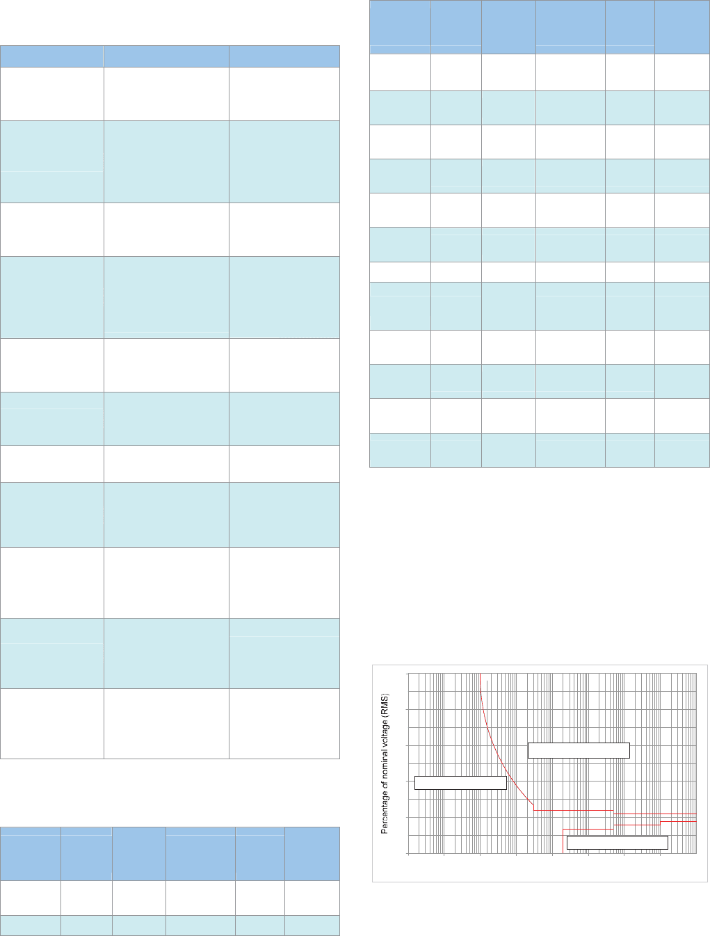
Table 23.1 provides a broad classification of the disturbances
that may occur on a power system, some typical causes of
them and the potential impact on equipment. From this Table,
it will be evident that the electricity supply waveform, often
thought of as composed of pure sinusoidal quantities, can
suffer a wide variety of disturbances. The following sections of
© 2011 Alstom Grid. Single copies of this document may be filed or printed for personal non-commercial use and must include this
copyright notice but may not be copied or displayed for commercial purposes without the prior written permission of Alstom Grid.
Network Protection & Automation Guide
23-2
this Chapter describe the causes in more detail, along with
methods of measurement and possible remedial measures.
Category Causes Impacts
Voltage dips
Local and remote faults
Inductive loading
Switch on of large loads
Tripping of sensitive equipment
Resetting of control systems
Motor stalling/tripping
Voltage surges
Capacitor switching
Switch off of large loads
Phase faults
Tripping of sensitive equipment
Damage to insulation and
windings
Damage to power supplies for
electronic equipment
Overvoltage
Load switching
Capacitor switching
System voltage regulation
Problems with equipment that
requires constant steady-state
voltage
Harmonics
Industrial furnaces
Non-linear loads
Transformers/generators
Rectifier equipment
Mal-operation of sensitive
equipment and relays
Capacitor fuse or capacitor
failures
Telephone interference
Power frequency variation
Loss of generation
Extreme loading conditions
Negligible most of time
Motors run slower
De-tuning of harmonic filters
Voltage fluctuation
AC motor drives
Inter-harmonic current components
Welding and arc furnaces
Flicker in:
Fluorescent lamps
Incandescent lamps
Rapid voltage change
Motor starting
Transformer tap changing
Light flicker
Tripping of equipment
Voltage imbalance
Unbalanced loads
Unbalanced impedances
Overheating in
motors/generators
Interruption of 3-phase
operation
Short and long voltage
interruptions
Power system faults
Equipment failures
Control malfunctions
CB tripping
Loss of supply to customer
equipment
Computer shutdowns
Motor tripping
Undervoltage
Heavy network loading
Loss of generation
Poor power factor
Lack of var support
All equipment without backup
supply facilities
Transients
Lightning
Capacitive switching
Non –linear switching loads
System voltage regulation
Control system resetting
Damage to sensitive electronic
components
Damage to insulation
Table 23.1: Power quality issues
Table 23.2 lists the limits given in Standard EN 50160 and
notes where other standards have similar limits.
Type of
disturbance
Voltage
Level
Limits
from
EN50160
Measurement
period
Typical
duration
Other
applicable
standards
Voltage
Variation
230V +/- 10% 95% of 1 week -
Voltage Dips 230V <10%<90% 10-1000/year 10ms –1sec IEEE 1159
Type of
disturbance
Voltage
Level
Limits
from
EN50160
Measurement
period
Typical
duration
Other
applicable
standards
Rapid voltage
changes
230V
+/-5% to
+/-10%
Several per day
Short
duration
Rapid voltage
changes
1kV-35kV <6% Per day
Short
duration
IEEE 1159
Short
Interruptions
230V >99% 20-200 per year Up to 3 mins
EN61000-4-
11
Long
Interruptions
230V >99% 10-50 per year >3 mins IEEE 1159
Transient
Overvoltage
230V
Generally
<6kV
Not specified <1ms IEEE 1159
Voltage
unbalance
230V
Undervoltage 230V <-10% Not specified >1 min IEEE 1159
Voltage surge 230V
<150% of
nominal
voltage
Not specified >200ms IEEE 1159
Voltage
fluctuations
230V 3% 10 min <200ms IEC 60827
Frequency
variation
+/- 1% 95% of 1 week Not specified
Measured over
10s
Frequency
variation
+4%, -6% 100% of 1 week Not specified
Measured over
10s
Harmonics
THD<8% up to
40th
95% of 1 week Not specified
Table 23.2: Power system disturbance classification to EN 50160
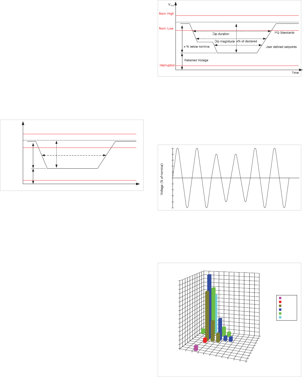
For computer equipment, a common standard that
manufacturers use is the ITI (Information Technology Industry)
curve, illustrated in Figure 23.1. Voltage disturbances that lie
in the area indicated as ‘safe’ should not cause a malfunction
in any way. However, some disturbances at LV levels that lie
within the boundaries defined by EN50160 might cause a
malfunction because they do not lie in the safe area of the ITI
curve. It may be necessary to check carefully which standards
are applicable when considering equipment susceptibility.
0.001
0
Duration of disturbance (ms)
0.01 0.1 1 10 100 10000
100000
50
100
150
200
250
300
350
400
450
500
1000
Withstand disturbance
Affected by disturbance
Affected by disturbance
Figure 23.1: ITI curve for equipment susceptibility
© 2011 Alstom Grid. Single copies of this document may be filed or printed for personal non-commercial use and must include this
copyright notice but may not be copied or displayed for commercial purposes without the prior written permission of Alstom Grid.
Chapter 23 Power Quality
23-3
23.3 CAUSES AND IMPACT OF POWER
QUALITY PROBLEMS
Each of the Power Quality disturbance categories detailed in
Table 23.1 is now examined in more detail as to the possible
causes and the impact on consumers.
23.3.1 Voltage Dips
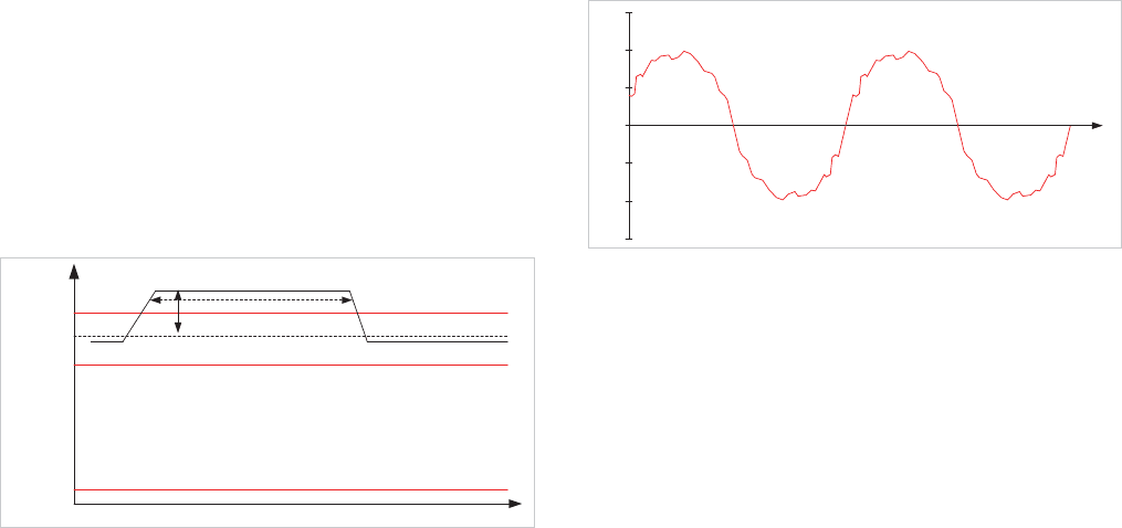
Figure 23.2 shows the profile of a voltage dip, together with
the associated definitions. The major cause of voltage dips on
a supply system is a fault on the system, that is sufficiently
remote electrically that a voltage interruption does not occur.
Other sources are the starting of large loads (especially
common in industrial systems), and, occasionally, the supply
of large inductive loads.
Dip magnitude: x% of declared
V
rms
Nom. High
Nom. Low
Interruption
PQ Standards
Dip duration
x % below nominal
Retained Voltage
Time
User defined setpoints
Figure 23.2: Voltage dip profile
Voltage dips due to the latter are usually due to poor design of
the network feeding the consumer. A voltage dip is the most
common supply disturbance causing interruption of production
in an industrial plant. Faults on a supply network will always
occur, and in industrial systems, it is often practice to specify
equipment to ride-through voltage dips of up to 0.2s. The
most common exception is contactors, which may well drop
out if the voltage dips below 80% of rated voltage for more
than 50-100ms. Motor protection relays that have an
undervoltage element setting that is too sensitive is another
cause. Since contactors are commonly used in circuits
supplying motors, the impact of voltage dips on motor drives,
and hence the process concerned, requires consideration.
Other network-related fault causes are weather–related (such
as snow, ice, wind, salt spray, dust) causing insulator
flashover, collisions due to birds, and excavations damaging
cables. Multiple voltage dips, as illustrated in Figure 23.3,
cause more problems for equipment than a single isolated dip.
Figure 23.3: Multiple voltage dip
The impact on consumers may range from the annoying (non-
periodic light flicker) to the serious (tripping of sensitive loads
and stalling of motors). Where repeated dips occur over a
period of several hours, the repeated shutdowns of equipment
can give rise to serious production problems. Figure 23.4
shows an actual voltage dip, as captured by a Power Quality
recorder.
-20
-40
-60
-80
-100
20
0
40
100
60
80
Time
Figure 23.4: Recording of a voltage dip
Typical data for undervoltage disturbances on power systems
during evolving faults are shown in Figure 23.5. Disturbances
that lie in the front right-hand portion of the histogram are the
ones that cause most problems, but fortunately these are quite
rare.
0
1
2
3
4
5
6
7
8
9
10
11
12
13
14
15
16
<0.5ms
Number of undervoltage disturbances recorded
0.5-1ms
1-5ms
5-10ms
10-50ms
50-100ms
100-500ms
0.5-1s
1-5s
5-10s
>10s
Duration of disturbance
11-20%
31-40%
51-60%
71-80%
91-100%
Retained voltage
Number of
incidents/yr
81-90%
91-100%
61-70%
51-60%
41-50%
0-10%
R
e
t
a
in
e
d
v
o
lt
a
g
e
Figure 23.5: Undervoltage disturbance histogram
© 2011 Alstom Grid. Single copies of this document may be filed or printed for personal non-commercial use and must include this
copyright notice but may not be copied or displayed for commercial purposes without the prior written permission of Alstom Grid.
Network Protection & Automation Guide
23-4
23.3.2 Voltage Surges/Spikes
Voltage surges/spikes are the opposite of dips – a rise that
may be nearly instantaneous (spike) or takes place over a
longer duration (surge). These are most often caused by
lightning strikes and arcing during switching operations on
circuit breakers/contactors (fault clearance, circuit switching,
especially switch-off of inductive loads). Figure 23.6 shows
the profile of a voltage surge.
V
rms
Nom. High
Nom. Low
Interruption
PQ Standards
Time
User defined setpoints
x% above nominal
Surge duration
Figure 23.6: Voltage surge profile
Equipment may suffer serious damage from these causes,
ranging from insulation damage to destruction of sensitive
electronic devices. The damage may be immediate and
obvious by the fact that equipment stops working, through to
failure at a much later date from deterioration initiated from a
surge or spike of voltage. These latter failures are very difficult
to distinguish from random failures due to age, minor
manufacturing defects, etc.
23.3.3 Overvoltages
Sustained overvoltages are not common. The most likely
causes are maladjusted voltage regulators on generators or on-
load tap changers, or incorrectly set taps on fixed-tap
transformers. Equipment failures may immediately result in
the case of severe overvoltages, but more likely is accelerated
degradation leading to premature failure without obvious
cause. Some equipment that is particularly sensitive to
overvoltages may have to be shut down by protective devices.
23.3.4 Harmonics
This is a very common problem in the field of Power Quality.
The main causes are Power Electronic Devices, such as
rectifiers, inverters, UPS systems, static var compensators, etc.
Other sources are electric discharge lamps, arc furnaces and
arc welders. In fact, any non-linear load will be a source of
harmonics. Figure 23.7 illustrates a supply waveform that is
distorted due to the presence of harmonics.
-100
-150
-50
0
50
100
150
Time
Figure 23.7: Supply waveform distorted due to the presence of
harmonics
Harmonics usually lead to heating in rotating equipment
(generators and motors), and transformers, leading to possible
shutdown. Capacitors may be similarly affected. If harmonic
levels are sufficiently high enough, protective devices may shut
the equipment down to avoid damage. Some equipment, such
as certain protection devices, may maloperate and cause
unnecessary shutdowns. Special provision may have to be
made to filter harmonics from the measured signals in these
circumstances. Interference may be caused to communication
systems. Overloading of neutral conductors in LV systems has
also occurred (the harmonics in each phase summing in the
neutral conductor, not cancelling) leading to failure due to
overheating. This is a particular risk in buildings that have a
large number of PCs etc. In such cases a neutral conductor
rated at up to 150% of the phase conductors has been known
to be required. Busbar risers in buildings are also at risk, due
to harmonic-induced vibration causing joint securing bolts, etc.
to work loose.
23.3.5 Frequency Variations
Frequency variations that are large enough to cause problems
are most often encountered in small isolated networks, due to
faulty or maladjusted governors. Other causes are serious
overloads on a network, or governor failures, though on an
interconnected network, a single governor failure will not
cause widespread disturbances of this nature. Network
overloads are most common in areas with a developing
electrical infrastructure, where a reduction in frequency may be
a deliberate policy to alleviate overloading. Serious network
faults leading to islanding of part of an interconnected network
can also lead to frequency problems.
Few problems are normally caused by this problem. Processes
where product quality depends on motor speed control may be
at risk but such processes will normally have closed-loop speed
controllers. Motor drives will suffer output changes, but
process control mechanisms will normally take care of this.
Extreme under- or overfrequency may require the tripping of
generators, leading to the possibility of progressive network
collapse through network overloading/underfrequency causes.
© 2011 Alstom Grid. Single copies of this document may be filed or printed for personal non-commercial use and must include this
copyright notice but may not be copied or displayed for commercial purposes without the prior written permission of Alstom Grid.
Chapter 23 Power Quality
23-5
23.3.6 Voltage Fluctuations
These are mainly caused by load variations, especially large
rapid ones such as are likely to occur in arc and induction
heating furnaces, rolling mills, mine winders, and resistance
welders.
Flicker in incandescent lamps is the most usual effect of
voltage fluctuations. It is a serious problem, with the human
eye being particularly sensitive to light flicker in the frequency
range of 5-15Hz. Because of the wide use of such lamps, the
effects are widespread and inevitably give rise to a large
number of complaints. Fluorescent lamps are also affected,
though to a lesser extent.
23.3.7 Voltage Unbalance
Unbalanced loading of the network normally causes voltage
unbalance. However, parts of the supply network with
unbalanced impedances (such as untransposed overhead
transmission lines) will also cause voltage unbalance, though
the effect of this is normally small.
Overheating of rotating equipment results from voltage
imbalance. In serious cases, tripping of the equipment occurs
to protect it from damage, leading to generation/load
imbalance or loss of production.
23.3.8 Supply Interruptions
Faults on the power system are the most common cause,
irrespective of duration. Other causes are failures in
equipment, and control and protection malfunctions.
Electrical equipment ceases to function under such conditions,
with undervoltage protection devices leading to tripping of
some loads. Short interruptions may be no more than an
inconvenience to some consumers (e.g. domestic consumers),
but for commercial and industrial consumers (e.g.
semiconductor manufacture) may lead to lengthy serious
production losses with large financial impact. Longer
interruptions will cause production loss in most industries, as
induction and synchronous motors cannot tolerate more than
1-2 seconds interruption without having to be tripped, if only
to prevent excessive current surges and resulting large voltage
dips on supply restoration. On the other hand, vital computer
systems are often fed via a UPS supply that may be capable of
supplying power from batteries for several hours in the event of
a mains supply failure. More modern devices such as Dynamic
Voltage Restorers can also be used to provide continuity of
supply due to a supply interruption. For interruptions lasting
some time, a standby generator can be provide a limited
supply to essential loads, but cannot be started in time to
prevent an interruption occurring.
23.3.9 Undervoltage
Excessive network loading, loss of generation, incorrectly set
transformer taps and voltage regulator malfunctions cause
undervoltage. Loads with a poor power factor (see Chapter 18
for Power Factor Correction) or a general lack of reactive
power support on a network also contribute. The location of
power factor correction devices is often important, incorrect
location resulting in little or no improvement.
The symptoms of undervoltage problems are tripping of
equipment through undervoltage trips. Lighting will run at
reduced output. Undervoltage can also indirectly lead to
overloading problems as equipment takes an increased current
to maintain power output (e.g. motor loads). Such loads may
then trip on overcurrent or thermal protection.
23.3.10 Transients
Transients on the supply network are due to faults, control and
protection malfunctions, lightning strikes, etc.
Voltage-sensitive devices and insulation of electrical equipment
may be damaged, as noted above for voltage surges/spikes.
Control systems may reset. Semiconductor manufacture can
be seriously affected unless the supplies to critical process
plant are suitably protected.
© 2011 Alstom Grid. Single copies of this document may be filed or printed for personal non-commercial use and must include this
copyright notice but may not be copied or displayed for commercial purposes without the prior written permission of Alstom Grid.
© 2011 Alstom Grid. Single copies of this document may be filed or printed for personal non-commercial use and must include this
copyright notice but may not be copied or displayed for commercial purposes without the prior written permission of Alstom Grid.
