Alciatore D.G., Histand M.B. Introduction to Mechatronics and Measurement Systems
Подождите немного. Документ загружается.


Confirming Pages
Figure 5.22 Comparator.
+
+
V
in
V
ref
V
ou
t
+
–
Figure 5.23 Comparator open-collector output.
V
in
V
ref
to external
circuit
+
_
ON/
OFF
5.13 Comparator 181
5.13 COMPARATOR
The comparator circuit illustrated in Figure 5.22 is used to determine whether one
signal is greater than another. The comparator is an example of an op amp circuit
where there is no negative feedback and the circuit exhibits infinite gain. The result
is that the op amp saturates. Saturation implies that the output remains at its most
positive or most negative output value. Video Demo 4.2 shows an interesting exam-
ple of amplifier saturation where an audio amplifier is clipping the output of a sound
wave from a microphone.
Certain op amps are specifically designed to operate in saturation as compara-
tors. The output of the comparator is defined by
V
out
+V
sat
V
in
V
ref
>
–V
sat
V
in
V
ref
<
⎩
⎨
⎧
=
(5.41)
where V
sat
is the saturation voltage of the comparator and V
ref
is the reference volt-
age to which the input voltage V
in
is being compared. The positive saturation value
is slightly less than the positive supply voltage, and the negative saturation value is
slightly greater than the negative supply voltage.
Often, comparators (e.g., LM339) have open-collector outputs, where the out-
put states are controlled by an output transistor operating at cutoff or saturation. This
type of output, illustrated in Figure 5.23 , is called an open-collector output because
the collector of the output transistor is not connected internally and requires an exter-
nal powered circuit. The output transistor is ON (at saturation) and the output is
effectively grounded when V
in
> V
ref
, and the output transistor is OFF (at cutoff) and
the output is open circuited when V
in
< V
ref
.
Video Demo
4.2Spectra of
whistling and
humming, and
amplifier
saturation
alc80237_ch05_161-196.indd 181alc80237_ch05_161-196.indd 181 1/3/11 4:10 PM1/3/11 4:10 PM

Confirming Pages
Figure 5.24 Effect of slew rate on a square wave.
input
output
ΔV
Δt
10%
90%
rise time
182 CHAPTER 5 Analog Signal Processing Using Operational Amplifiers
5.14 THE REAL OP AMP
An actual operational amplifier deviates somewhat in characteristics from an ideal
op amp. The best way to familiarize yourself with an IC is to review its specifica-
tions in the data book provided by the manufacturer. Complete descriptions of op
amps and many other analog ICs are found online or in manufacturers’ Linear data
books. Some of the more important parameters that can be found on op amp data
sheets are described in the next section.
As the ideal operational amplifier model implies, real op amps have a very high
input impedance, so very little current is drawn at the inputs. At the same time,
there is very little voltage difference between the input terminals. However, the input
impedance of a real op amp is not infinite, and its magnitude is an important terminal
characteristic of the op amp.
Another important terminal characteristic of any real op amp is the maximum out-
put voltage that can be obtained from the amplifier. Consider an op amp circuit with a
gain of 100 set by the external resistors in a noninverting amplifier configuration. For a
1 V input, you would expect a 100 V output. In reality, the maximum voltage output will
be about 1.4 V less than the supply voltage to the op amp for a large load impedance. So
if a 15 V supply is being used, the maximum voltage output would be approximately
13.6 V, and the minimum would be 13.6 V. Attempts to drive the output beyond this
range result in saturation and clipping at the maximum output-voltage-swing limits.
Two other important characteristics of a real op amp are associated with its response
to a square wave input. When you apply a square wave input to an amplifier circuit, you
ideally would expect a square wave output. However, as illustrated in Figure 5.24 , the
output cannot change infinitely fast; instead, it exhibits a ramp from one level to the
next. In order to quantify the op amp step response, two parameters are defined:
■ Slew rate —The maximum time rate of change possible for the output voltage
SR
ΔV
Δt
-------=
(5.42)
■ Rise time —The time required for the output voltage to go from 10% to 90%
of its final value. This parameter is specified by manufacturers for specific
load and input parameters.
alc80237_ch05_161-196.indd 182alc80237_ch05_161-196.indd 182 1/3/11 4:10 PM1/3/11 4:10 PM
Confirming Pages
5.14 The Real Op Amp 183
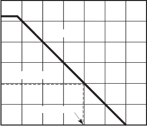
Another important characteristic of a real op amp is its frequency response. An
ideal op amp exhibits infinite bandwidth. In practice, however, a real op amp has a
finite bandwidth, which is a function of the gain established by external components.
To quantify this dependence of bandwidth on the gain, another definition is used: the
gain bandwidth product (GBP). The GBP of an op amp is the product of the open-
loop gain and the bandwidth at that gain. The GBP is constant over a wide range of
frequencies because, as shown in Figure 5.25 , typical op amps exhibit a linear loglog
relationship between open-loop gain and frequency. Note how the op amp’s gain
decreases with input signal frequency. Higher-quality op amps have larger GBPs.
The open-loop gain is a characteristic of the op amp without feedback. The closed-
loop gain is the overall gain of an op amp circuit with feedback. The closed-loop
gain is always limited by the open-loop gain of the op amp. For example, a nonin-
verting amplifier with a closed-loop gain of 100 would have a bandwidth of 0 Hz
to approximately 10,000 Hz as illustrated in Figure 5.25 . The frequency where the
open-loop gain curve first starts to limit the closed-loop gain is called the fall-off
frequency. As you increase the gain of a circuit, you limit its bandwidth. Likewise,
if your application requires only a small bandwidth (e.g., in a low-frequency applica-
tion), larger gains can be used without signal attenuation or distortion.
5.14.1 Important Parameters from Op Amp Data Sheets
Most of the parameters used to describe the characteristics of actual op amps are
listed and described here. These parameters are important when designing and using
op amp circuits.
A. Input Parameters
■ Input Voltage ( V
icm
)—This is the maximum input voltage that can be
applied between either input and ground. In general, this voltage is equal
to the supply voltage.
Figure 5.25 Typical op amp open- and closed-loop response.
frequency (Hz)
gain
110
10
2
10
3
10
5
10
6
10
7
10
4
1
10
10
2
10
3
10
4
10
5
10
6
open loop
closed loop
fall-off frequency
dB
0
20
40
60
80
100
120
alc80237_ch05_161-196.indd 183alc80237_ch05_161-196.indd 183 1/3/11 4:10 PM1/3/11 4:10 PM
Confirming Pages
184 CHAPTER 5 Analog Signal Processing Using Operational Amplifiers
■ Input Offset Voltage ( V
io
)—This is the voltage that must be applied to one
of the input terminals, with the other input being at 0 V, to give a zero output
voltage. Remember, for an ideal op amp, the output voltage offset is 0.
■ Input Bias Current ( I
ib
)—This is the average of the currents flowing into both
inputs when the output voltage is 0. Ideally, the two input currents are 0.
■ Input Offset Current ( I
io
)—This is the difference between the input
currents when the output voltage is 0.
■ Input Voltage Range ( V
cm
)—This is the range of allowable common mode
input voltage, where the same voltage is placed on both inputs.
■ Input Resistance ( Z
i
)—This is the resistance “looking into” either input
with the other input grounded.
B. Output Parameters
■ Output Resistance ( Z
oi
)—This is the internal resistance of the op amp’s
output circuit (i.e., “looking into” the op amp).
■ Output Short Circuit Current ( I
osc
)—This is the maximum output current
that the op amp can deliver to a load.
■ Output Voltage Swing ( V
o max
)—This is the maximum peak-to-peak out-
put voltage that the op amp can supply without saturating or clipping.
C. Dynamic Parameters
■ Open Loop Voltage Gain ( A
OL
)—This is the ratio of the output to the
differential input voltage of the op amp without external feedback.
■ Large Signal Voltage Gain—This is the ratio of the maximum voltage
swing to the change in the input voltage required to drive the output from
0 to a specified voltage.
■ Slew Rate (SR)—This is the time rate of change of the output voltage,
assuming a step input, with the op amp circuit having a voltage gain of 1.
D. Other Parameters
■ Maximum Supply Voltage ( V
s
)—This is the maximum positive and
negative voltage permitted to power the op amp.
■ Supply Current—This is the current that the op amp draws from the power supply.
■ Common Mode Rejection Ratio (CMRR)—This is a measure of the ability
of the op amp to reject signals of equal value at the inputs. It is the ratio of
the difference mode gain (the output gain corresponding to the difference
between the inputs) to the common mode gain (the output gain occurring
when the same voltage is applied to both inputs), usually expressed in
decibels (dB).
■ Channel Separation—Whenever there is more than one op amp in a single
package, such as the 747 op amp IC, a certain amount of cross-talk is
present. That is, a signal applied to the input of one op amp produces a finite
output signal in the second op amp, even though there is no direct connection.
alc80237_ch05_161-196.indd 184alc80237_ch05_161-196.indd 184 1/3/11 4:10 PM1/3/11 4:10 PM
Confirming Pages
5.14 The Real Op Amp 185
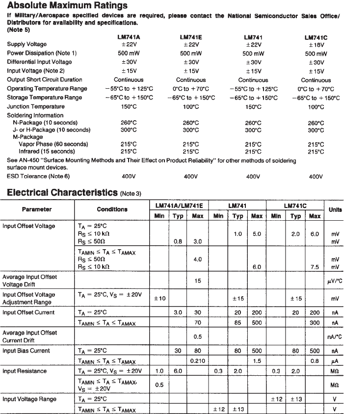
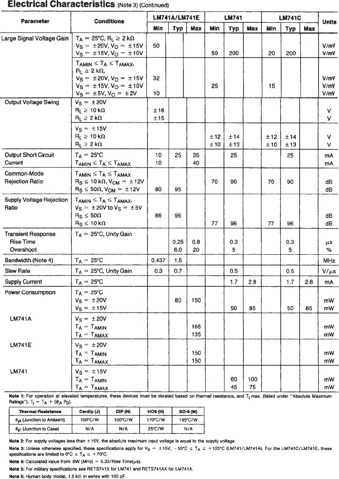
Data for each of these parameters are usually provided in IC manufacturers’
Linear data books, which are available online. Figure 5.26 is a reproduction of the
LM741 data sheet from National Semiconductor. It is divided into a maximum rat-
ings section and an electrical characteristics section. This data sheet is typical of
Figure 5.26 Example op amp data sheet. (Courtesy of National Semiconductor,
Santa Clara, CA)
(continued)
alc80237_ch05_161-196.indd 185alc80237_ch05_161-196.indd 185 1/3/11 4:10 PM1/3/11 4:10 PM
Confirming Pages
186 CHAPTER 5 Analog Signal Processing Using Operational Amplifiers
Figure 5.26 (continued)
alc80237_ch05_161-196.indd 186alc80237_ch05_161-196.indd 186 1/3/11 4:10 PM1/3/11 4:10 PM
Confirming Pages
5.14 The Real Op Amp 187
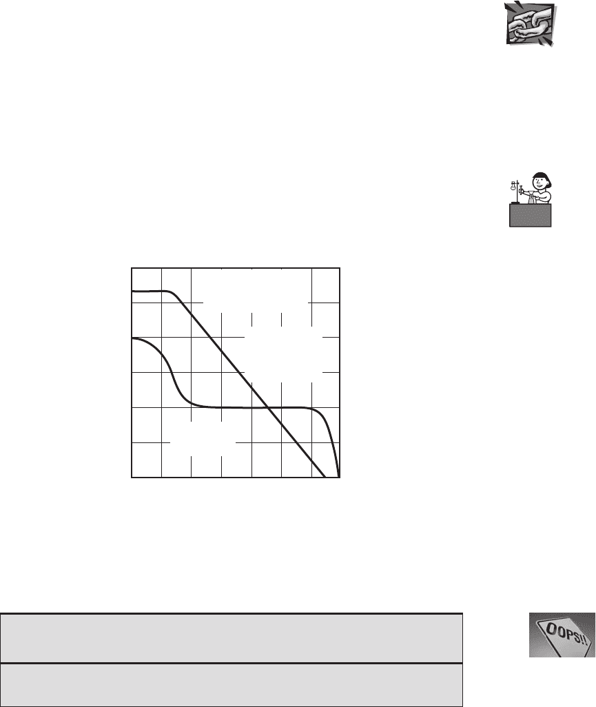
those from other manufacturers. Figure 5.27 shows the frequency response charac-
teristics of the TL071. These types of graphs are also typically provided on op amp
data sheets. Internet Links 5.1 and 5.2 point to the complete data sheets for both
the 741 and the TL071. Lab Exercise 6 explores how some of the parameters and
information reported in the data sheets are important in understanding how various
op amp circuits respond to various inputs.
As you gain practical experience with op amp circuits, you should develop
an appreciation of the significance of the many parameters affecting op amp
performance.
Figure 5.27 TL071 FET input op amp. (Courtesy
of Texas Instruments, Dallas, TX)
LARGE-SIGNAL
DIFFERENTIAL VOLTAGE AMPLIFICATION
and PHASE SHIFT
vs
FREQUENCY
AV D
_
Differential Voltage Amplification
Phase Shift
f
_
Frequency
_
Hz
DIFFERENTIAL
VOLTAGE
AMPLIFICATION
(left scale)
PHASE SHIFT
(right scale)
10
6
10
5
10
4
10
3
10
2
10
1
1
1 10 100 1 k 10 k 100 k 1 M 10 M
180°
135°
90°
45°
0°
V
CC ±
= ± 5 V to ±15V
R
L
= 2 kΩ
T
A
= 25° C
■ CLASS DISCUSSION ITEM 5.7
Real Integrator Behavior
Reflecting back on Class Discussion Item 5.4, if the integrator is made with a real
op amp, what happens to the output in contrast to that of the ideal integrator?
Lab Exercise
Lab 6
Operational
amplifier circuits
Internet Lin
k
5.1741 op amp
data sheet
5.2TL071 FET
input op amp data
sheet
alc80237_ch05_161-196.indd 187alc80237_ch05_161-196.indd 187 1/3/11 4:10 PM1/3/11 4:10 PM
Confirming Pages
188 CHAPTER 5 Analog Signal Processing Using Operational Amplifiers
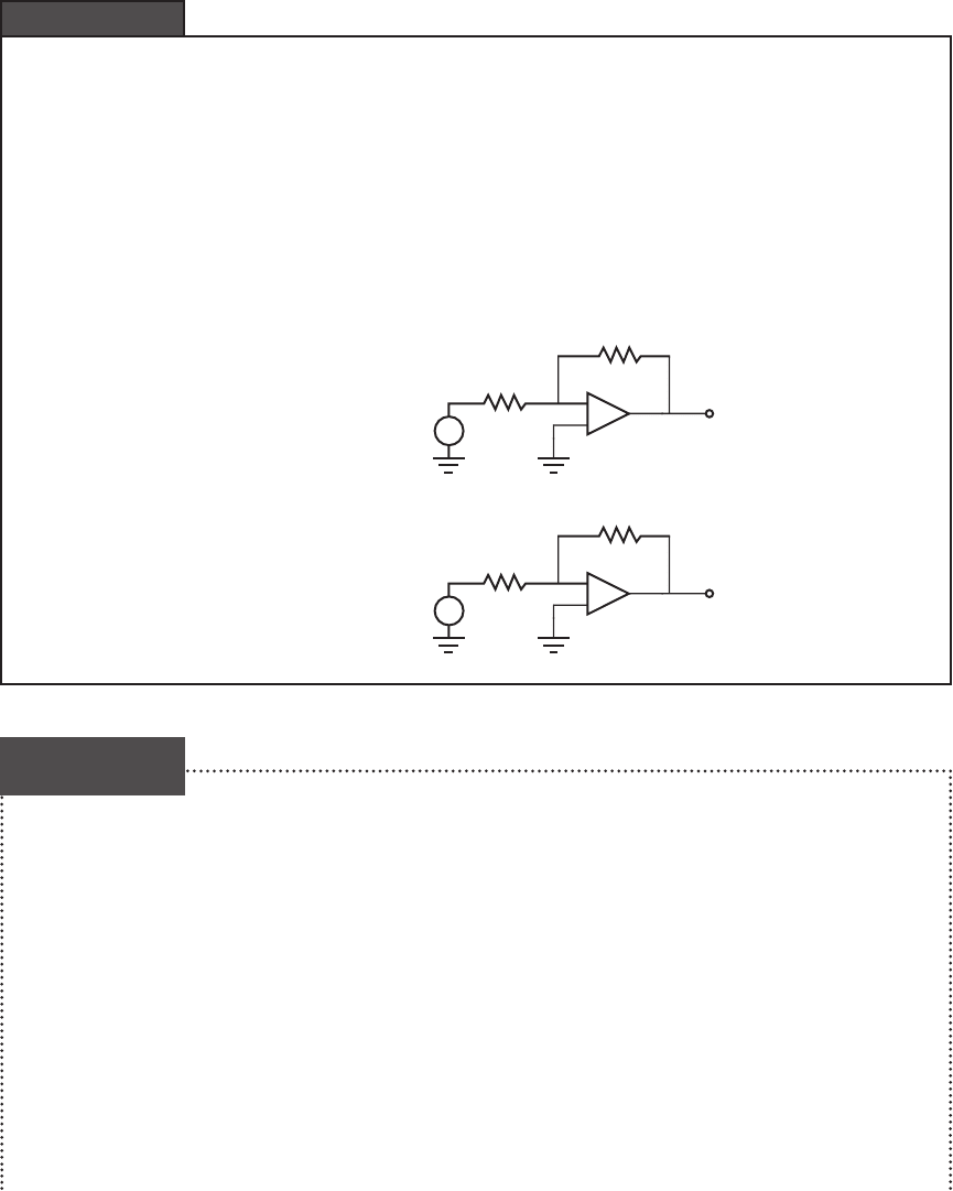
The ideal model of the op amp would imply that if you constructed the following two op
amp circuits in the laboratory, they would have the same gain. Ideally, each circuit would
have a gain of 2. However, the top circuit would be a very poor design and not function as
expected. The reason for this can be found by considering the Output Short Circuit Current
found on the specification sheet for the op amp. From Figure 5.26 , the value for a LM741
is typically 25 mA. This is the largest current that the output can source. But, looking at the
circuit, the output current is V
out
/ 2 Ω, and because V
out
2 V
in
10 V, the output current
would be 5 A! This is far above the current sourcing capability of the op amp. To avoid this
problem, larger resistances such as the ones shown in the bottom circuit are used. Here, the
output current is 5 mA (10 V / 2 kΩ), which is well within the op amp specification.
–
+
+
5 V
1 Ω
2 Ω
V
ou
t
–
+
+
5 V
1 kΩ
2 kΩ
V
ou
t
Sizing Resistors in Op Amp Circuits
EXAMPLE 5.1
Interfacing prosthetic devices to the human body presents one of the most interesting and
challenging problems for engineers. These problems pose a number of medical and engi-
neering challenges in the fields of materials, fluids, electronics, control, and mechanics.
Think of the artificial heart, dialysis machine, hip joint replacement, osmotic skin patch, and
artificial retina as examples. As we develop improved technological products, we find very
important applications in bioengineering. Let us consider one important problem that uses
our knowledge of operational amplifiers.
Suppose you would like to design a prosthetic limb (e.g., an artificial arm or leg)
that could be controlled by the thoughts of the wearer. Early prosthetic limbs were either
purely passive or somewhat mechanically controlled by contracting other muscles. A novel
approach however, would be to provide thought control of the limb. Two possibilities pre-
sent themselves: neural control or myogenic control. For neural control we would have to
electrically tap the nervous system, which still is a problem that has not been completely
solved technically. Myogenic control is easier to realize. When a muscle is caused to move
or twitch, the tiny movement of electrolytes in the muscles below the skin cause an electric
Myogenic Control of a Prosthetic Limb
DESIGN
EXAMPLE 5.1
alc80237_ch05_161-196.indd 188alc80237_ch05_161-196.indd 188 1/3/11 4:10 PM1/3/11 4:10 PM

Confirming Pages
5.14 The Real Op Amp 189
field that induces a small voltage on the surface of the skin. This voltage is quite small,
otherwise we would shock each other every time we touched. It ranges from microvolts to
millivolts and may be mixed with other biopotential signals. The problem then is to sense
and isolate this small voltage and convert it into a signal capable of switching something like
an electric motor that could be attached to a prosthetic device. So here is our problem: How
can we design a mechatronic system that uses the surface skin potential from a muscle as an
input to control an actuator such as an electric motor?
Let us begin by outlining what the approach will be. First we have to tap the skin potential
with a special surface electrode. Then we have to amplify the signal and filter it to eliminate
unwanted noise components and achieve the correct frequency response. Then we need to
convert it to a form that allows setting different levels for a control strategy. Finally, we need to
drive an electric motor that requires significant current. You currently have the design capabil-
ity to do all of these things. We start by looking at the transducer to sense the skin potential.
The electric fields that occur in living tissue are caused by charge separations in electro-
lytes and not by the movement of electrons. In order to sense the voltage at the skin, we need a
transducer that converts subdermal (below the skin) electrolyte ion currents to electron currents
in our electronic system. Silver–silver chloride electrodes have this property. So if we place
a silver chloride electrode on the skin and couple it with a conducting gel, we can sense the
body’s voltage at that location. The magnitude of the voltage is related to how much a subcuta-
neous (beneath the skin) muscle contracts. This voltage is the myoelectric signal of interest. The
problem that remains is that the electrode produces a very small signal, at best a few millivolts.
Also, a considerable amount of 60 Hz background noise and other signals can obscure the sig-
nal associated with the muscle. Moreover, the electrode-skin connection has a high impedance.
This is an application where an instrumentation amplifier is necessary to provide the
high input impedance, high common mode rejection ratio, and gain necessary to extract the
biopotential signal produced by the contracting muscle. The following figure displays the
preamplifier stage of our electromyogenic (EMG) detector. For the components shown, it
should be easy to create a CMRR in excess of 60 dB and a gain of 125 with an input imped-
ance of 10 MΩ. Note that two active (differential) electrodes 1 and 2 will be mounted close
together above the muscle. The third electrode is a ground reference. This circuit is satisfac-
tory in capturing the EMG signal.
A
electrode 1
electrode 2
electrode 3
–
+
–
+
+
–
The instrumentation amplifier was chosen because it can extract a very small sig-
nal difference between the two signal electrodes (electrodes 1 and 2) while significantly
(continued )
alc80237_ch05_161-196.indd 189alc80237_ch05_161-196.indd 189 1/3/11 4:10 PM1/3/11 4:10 PM

Confirming Pages
190 CHAPTER 5 Analog Signal Processing Using Operational Amplifiers
attenuating noise common to both electrodes. This eliminates a considerable amount of
60 Hz common mode noise (resulting from electromagnetic interference) and other signals
common to both electrodes. However, something called a motion artifact can still occur due
to relative motion between the electrodes and the tissue. Relative motion can produce volt-
ages sufficient to saturate the second-stage amplifier. The frequencies of the motion artifact
are usually at the low end of the bandwidth of the EMG signals. Therefore, a 2 Hz high-pass
filter on the input of the second stage of the amplifier that follows can be used to reduce
these artifacts. Signal “A” is the output from the instrumentation amplifier circuit and signal
“B” is the output of the op-amp-based filter. The filter circuit is a combination of an RC filter
and a noninverting amplifier. The capacitor in the op amp feedback loop limits the gain at
frequencies higher than those of interest.
A
B
–
+
At this point, the EMG signal (signal “B”) observed on an oscilloscope would look
like the following, where the large amplitude bursts are associated with muscle contractions.
muscle
contractions
This is a rather high-frequency signal with components between a few Hz and 250 Hz.
To make this signal more useful for control purposes, we need to extract the envelope of the
signal between 0 V and its maximum positive amplitude. We can accomplish this with a
rectifier and a low-pass filter. A normal silicon diode would not be satisfactory to rectify the
signal because it requires a 0.7-V turn-on voltage, which is larger than the amplitude of the
input signal. Because the signal is very small, we must use a precision rectifier circuit (see
the figure that follows) that more closely approximates the action of an ideal diode.
B
–
+
–
+
low-pass
filter
10 k
10 k
10 k
C
20 k
20 k
(continued )
alc80237_ch05_161-196.indd 190alc80237_ch05_161-196.indd 190 1/3/11 4:10 PM1/3/11 4:10 PM
