Xin Q. Diesel Engine System Design
Подождите немного. Документ загружается.

580 Diesel engine system design
© Woodhead Publishing Limited, 2011
9.6 Analytical valvetrain system design and
optimization
Analytical valvetrain design refers to using advanced simulation tools in
each of the following design steps to optimize the relationship between the
parameters in the valvetrain system. The scope of the valvetrain system
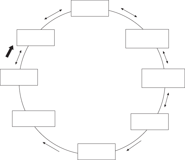
design is illustrated in Fig. 9.22. The key steps in the valvetrain design are
summarized as follows.
1. Select an appropriate target of valvetrain no-follow speed by the analysis
of vehicle driving and engine motoring or braking operation.
2. Use engine cycle simulation to determine the optimum valve event
duration, valve timing, and valve overlap size based on the best trade-off
between low engine speeds and high speeds. This needs to be conducted
in a coupled analysis with turbocharger matching since engine delta P
has a direct impact on gas exchange and the reverse valve ow. The
effect of valve recession on the combustion chamber ‘K-factor’ also
needs to be considered.
Spring design
Cam design
Engine
performance
Camshaft torsional
vibration
Camshaft load
analysis
Valve and piston
motion
Interactive optimized design of
valvetrain system
Valvetrain
Kinematics and
dynamics
Contact stresses,
friction, wear,
lubrication
(Start)
9.22 Concept of valvetrain system optimization.
Diesel-Xin-09.indd 580 5/5/11 11:59:07 AM
581Advanced diesel valvetrain system design
© Woodhead Publishing Limited, 2011
3. Determine the gas loading from the cylinder and the port acting on the
valvetrain by engine cycle simulation based on the preliminary valve
lift.
4. Select a preliminary exhaust valve spring preload based on the engine
ring and braking requirements. Select a preliminary valve spring rate
based on the dynamic simulation of valve acceleration.
5. Simulate the effect of gas loading on valvetrain vibration.
6. With given valve timing, valvetrain stiffness and weight, valve size and
valvetrain lash, optimize the following design parameters all together
in the valvetrain system by using a cam design tool and a valvetrain
dynamics simulation model to meet all the design criteria: the maximum
valve lift, rocker arm ratio, cam acceleration shape, cam base circle
radius, roller radius of the follower, cam radius of curvature, valve spring
preload, and spring rate. For example, the cam base circle radius should
be maximized within the allowable limits of space and weight. This
helps reduce the cam stress and maximize the breathing performance.
Higher rocker ratio results in higher cam force and cam stress. Lower
rocker ratio requires higher cam lift (for a given valve lift), higher cam
acceleration, and smaller radius of curvature at the cam nose.
7. Conduct valve spring design optimization on the spring diameter, the
coil diameter and the number of coils to maximize the spring natural
frequency.
8. Re-iterate from steps 2 to 7 until satisfactory trade-offs between all the
design parameters are obtained.
It should be apparent that valvetrain design is very complex due to the large
number of design parameters involved and the complex interactions among
them. An iterative process or even DoE optimization is often required.
Constructing the parametric design charts with a graphical design method is
very powerful to enhance the understanding of the parametric relationships
(e.g., Fig. 9.17 for the cam and Fig. 9.21 for the valve spring). More
information on valvetrain architecture design is provided by Jacques (1997),
Clarke and Innes (1997), and Buuck and Hampton (1997). Valvetrain system
design optimizations are presented by Seidlitz (1990), Ernst et al. (1993),
and Keribar (2000).
9.7 Variable valve actuation (VVA) engine
performance
9.7.1 The need for variable valve actuation (VVA)
In the conventional xed-cam valvetrain, the camshaft controls the intake
and exhaust valves. Valve timing, valve lift, and event duration are all xed
values specic to the camshaft design. The optimum valve timing is usually
Diesel-Xin-09.indd 581 5/5/11 11:59:07 AM
582 Diesel engine system design
© Woodhead Publishing Limited, 2011
a compromise between different engine operating conditions (e.g., different
speeds or loads), and the optimum is determined to achieve a high volumetric
efciency or a low BSFC at a selected working condition. Engine valve ow
directly affects the breathing of the engine cylinder and the thermodynamic
cycle process of the engine. Air and fuel ows consist of the energy ows
of the internal combustion engine. Modern diesel engines are equipped
with electronically-controlled exible fuel injection systems and air/gas/
EGR control valves. Variable geometry turbochargers are also widely used
in production engines to regulate gas ows. The only part in the air system
left for revolutionary rather than evolutionary change is the valvetrain. An
electronically-controlled air management variable valve actuation (VVA)
system is highly desirable for modern diesel engines.
Like the expectation for variable compression ratio for optimum engine
performance without the compromise in efciency at different operating
conditions throughout the working range of the engine, a exible variation
in engine valve actuation in crank angle resolution has been a dream of
engine designers since the era of steam engines more than a century ago.
In fact, the rst study on VVA for internal combustion engines dates back
to as early as 1902 when Louis Renault conceived a simple VVA device
for a spark ignition engine. However, only in the last twenty years has the
engine industry experienced a rapid progress in VVA research, evidenced
by a drastic increase in the number of publications and patents, and the
materialization in production of spark ignition engines. This fast growth is
primarily the result of the advent of electronic engine controls applied to
VVA devices as well as market pressure on fuel economy improvement.
Various forms of VVA have been commonly used in today’s gasoline
engines in automotive production since the 1980s. The VVA application to
diesel engines has lagged behind. The biggest reason is that the conventional
gasoline engine relied on throttled operation at part load where the use of
VVA to eliminate or reduce the pumping loss due to intake throttling to
improve fuel economy can be easily justied. Intake throttle reduces the
cylinder pressure during the intake stroke. The cylinder pressure difference
between the exhaust stroke and the intake stroke forms the pumping loss.
The diesel engine inherently runs without the throttle and has a narrower
engine speed range (e.g., up to 3000 rpm for HD diesel and 4500 rpm for
LD diesel). Therefore, the benet of using VVA for the diesel engine has
traditionally been believed to be far more limited than the gasoline engine.
The questions on the benets of VVA for the diesel engine have often focused
on the cost–benet ratio for valve timing optimization and other advanced
design features such as engine compression brake.
Future advanced diesel engine technologies require a new look at the
potential of VVA. These include pumping loss reduction, HCCI combustion,
cylinder deactivation, engine brake, reconciliation between the engine valves
Diesel-Xin-09.indd 582 5/5/11 11:59:07 AM
583Advanced diesel valvetrain system design
© Woodhead Publishing Limited, 2011
(with the control in crank angle resolution) and air system control valves
(with the control in engine cycle resolution), and valve timing optimization.
The driving forces for diesel VVA are usually fuel economy improvement,
cost reduction via consolidating all air ow control features, and customer
demands for special features such as low-speed torque, reduced turbocharger
lag during low-speed light-load ‘tip-in’ transient accelerations, and engine
compression brake.
9.7.2 Classification of VVA
VVA generally refers to the ability to vary some or all of the following:
valve opening and closing timing or valve event duration, maximum valve
lift, and the rising rate of valve opening and closing. Although numerous
patents exist for VVA, the VVA technology can be classied into two groups
with various complexities: (1) the devices using camshafts (e.g., cam phase
shifter or phaser, cam lobe switcher, cam-driven mechanical VVA with
variable tappets or rockers, cam-based ‘lost-motion’ VVA, variable cam lobe
contour, or the ‘3-D’ cam); and (2) camless devices (e.g., electro-hydraulic,
electro-magnetic, electro-mechanical, pneumatic). VVA can also be classied
into VVT (variable valve timing) and VVL (variable valve lift) according
to the functionality.
An example of cam phase shifter is that the intake and exhaust cams are
located on separate camshafts in a double-overhead-cam valvetrain, and
the phase relationship and the valve overlap period can be varied between
the two sets of cams. Cam phase shifters are widely used in the gasoline
engine VVA. Camless VVA is more suitable for diesel engines due to its
versatile features in crank-angle-resolution air management. The camless
engine can achieve any valve event at any crank angle locations to any
valve lift position and hold it for any duration, thus exibly optimizing the
engine performance. In camless VVA, the traditional valvetrain (camshaft,
pushrods, lifters, rocker arms, and valve springs) is replaced by small and
fast electronically-controlled actuators.
More detailed classications of VVA systems and the introduction to
their design mechanisms are given by Stone and Kwan (1989). Dresner and
Barkan (1989a) classied VVA into 15 basic types of concepts.
9.7.3 Design challenges of VVA
The benets of VVA on the gasoline engine have been well established,
and the current development focus is to reduce the cost and the weight, and
improve the reliability of the VVA mechanisms. Better reliability can be
achieved by reducing complexity and valve seating velocity (e.g., with soft
landing), improving the accuracy and the repeatability of valve timing and
Diesel-Xin-09.indd 583 5/5/11 11:59:07 AM
584 Diesel engine system design
© Woodhead Publishing Limited, 2011
valve event, and ensuring no collision between the valve and the piston. The
performance at low engine oil pressures and temperatures is also another
design challenge for the hydraulic-driven VVA systems.
The parasitic loss of the VVA system is generally higher than that of the
conventional cam-driven valvetrain. A low friction design is critical for any
VVA system in order to avoid negating the fuel economy benets obtained
from the better gas exchange processes of the VVA. For example, in the
camless electro-hydraulic valvetrain, the energy consumption is proportional
to the maximum valve lift generated. A low lift can be used at low speeds/
loads in order to reduce the energy consumption of the valvetrain without
a signicant negative impact on engine breathing and fuel economy.
9.7.4 Interaction of VVA with other air system
components
The valve timing effect on internal combustion engine performance is discussed
in detail by Asmus (1982), Stas (1999), Thring (1990), and Leonard et al.
(1991). VVA technologies for both gasoline and diesel engines are extensively
reviewed by Gray (1988), Stone and Kwan (1989), and Dresner and Barkan
(1989a, 1989b). Camless engines and their performance are elaborated by
Mardell and Cross (1988), Schechter and Levin (1996), Pischinger et al.
(2000), Salber et al. (2001), Tai et al. (2002), Schernus et al. (2002), and
Picron et al. (2008). A physics-based volumetric efciency model has been
introduced by Turin et al. (2008). Moreover, a thermodynamic second-law
analysis applied to VVA has been conducted by Anderson et al. (1998).
There is a wealthy body of literature addressing engine valve timing and
VVA performance. However, no study has been conducted to address the
theoretical relationship between VVA and other air system components.
The air system in this book refers to the turbocharger, the EGR system, the
manifolds, and the valvetrain. In diesel engine system design, it is important to
understand the role of valve timing and VVA in the entire air system so that
a wise system-level design solution can be selected to reconcile or simplify
the functionality between different components and avoid redundancy. This
section provides a theoretical analysis to address the relationship among
several air system technologies such as VVA, cylinder deactivation, air
control valves, EGR, and turbocharging.
The operation of the engine valves affects the number of strokes (e.g.,
two-stroke or four-stroke operation), effective engine displacement (e.g., via
cylinder deactivation by disabling the valve lift), effective engine compression
ratio (i.e., via IVC timing change), effective engine expansion ratio (i.e., via
EVO), volumetric efciency (via either valve event duration or effective valve
opening area), and eventually the engine in-cylinder thermodynamic cycle
process. The air/gas control valves in the engine gas ow network circuit and
Diesel-Xin-09.indd 584 5/5/11 11:59:07 AM
585Advanced diesel valvetrain system design
© Woodhead Publishing Limited, 2011
the turbocharger also affect the engine air ow through their roles outside the
cylinders at engine cycle resolution. Their effects are different from VVA on
air/EGR ow and pumping loss. However, the valvetrain and the cylinder
can be viewed as a lumped element, characterized by volumetric ef ciency,
in the gas ow network where the valvetrain essentially behaves as ow
restriction ori ces. The engine air ow rates and pressures are determined
by all the ow restriction ori ces in the ow network. For example, the
intake manifold boost pressure increases when the downstream intake valve
ow area reduces by the Miller cycle with early IVC. The exhaust manifold
pressure increases when the downstream turbine ow area reduces. The
pressure built up is also related to the air/gas ow rate through the ori ce.
For example, closing the intake throttle reduces the engine air ow rate so
that the intake manifold pressure becomes very low in front of the engine
intake valve ori ce.
The impact of valvetrain and VVA designs on engine performance can best
be understood through the roles of volumetric ef ciency, pumping loss and
EGR, driving capability in the four core equations presented in the air system
theory in Chapter 4, namely, equation 4.40 (engine volumetric ef ciency),
4.44 (EGR circuit pressure drop), 4.47 (turbocharger power balance) and 4.57
(turbine ow). These four core equations determine the engine air ow rate
and the pumping loss. The roles of different air system design and control
parameters, including any competing technologies, can be clearly comprehended
via the parametric relationships revealed in these four equations.
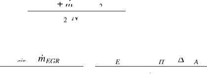
The intake manifold air–EGR mixture non-trapped volumetric ef ciency
h
vol
of a four-stroke internal combustion engine given by equation 4.40 in
Section 4.4 is shown as follows:
h
vo
l
ai
rE
GR
a
gas
aE
E
mm
ai
mm
ai
rE
mm
rE
TR
a
TR
a
pN
aE
pN
aE
V
E
V
E
=
2(
+
mm +mm
rE
mm
rE
+
rE
mm
rE
)
rE
)
rE
GR
)
GR
mm )mm
rE
mm
rE
)
rE
mm
rE
2
TR
2
TR
pN
2
pN
)
)
This equation can be rearranged in the following form:
2(
+
)
=
(
–
2
)
)
mm
+mm +
)mm )
R
N
Vp
(Vp(
pp
ai
mm
ai
mm
rE
)
rE
)
mm
rE
mm
+mm +
rE
+mm +
)mm )
rE
)mm )
GR
)
GR
)
gas
E
vo
lE
Vp
lE
Vp
pp
IT
pp
C
h
DD
ppDDpp
– pp – DD – pp –
pp
IT
ppDDpp
IT
pp
AC
CACC
AACA
CACACCAC
a
T
)
2
T
2
T
9.30
where N
E
is the engine speed, V
E
is the effective engine displacement, T
2a
is
the intake manifold gas temperature, p
2a
is the intake manifold pressure, p
2
is the compressor outlet pressure, Dp
IT
is the pressure drop associated with
the intake throttle, and Dp
CAC
is the pressure drop of the charge air cooler.
Equation 9.30 shows that in order to reach a given air and EGR ow rate
requirement, the following ve technologies need to match well (shown on
the right side of equation 9.30): valvetrain design (h
vol
), engine displacement
(e.g., cylinder deactivation), turbocharging (p
2
), intake throttle (Dp
IT
), and
air/EGR charge cooling (T
2a
).
Diesel-Xin-09.indd 585 5/5/11 11:59:08 AM
586 Diesel engine system design
© Woodhead Publishing Limited, 2011
The pressure drop and the opening duration of the intake and exhaust
valves largely affect the volumetric ef ciency. Fukutani and Watanabe (1979)
indicated that volumetric ef ciency could be correlated to a mean intake
Mach number and a Mach index. When the Mach number approaches 0.5,
the volumetric ef ciency decreases drastically because the ow becomes
choked during part of the intake stroke. In general, it is always desirable
to have a large valve ow area and a high port ow coef cient in order to
minimize pumping loss and increase volumetric ef ciency.
The four core equations of the engine air system are presented as follows:
2(
+
)
=
(
–
2
)
)
mm
+mm +
)mm )
R
N
Vp
(Vp(
pp
ai
mm
ai
mm
rE
)
rE
)
mm
rE
mm
+mm +
rE
+mm +
)mm )
rE
)mm )
GR
)
GR
)
gas
E
vo
lE
Vp
lE
Vp
pp
IT
pp
C
h
DD
ppDDpp
– pp – DD – pp –
pp
IT
ppDDpp
IT
pp
AC
CACC
AACA
CACACCAC
a
nE
GR
out
dE
GR
EG
RE
EGREEG
GRc
ool
T
pp
EGRi
pp
EGRi
nE
pp
nE
fC
mT
EG
mT
EG
RE
mT
RE
EGREEG
mT
EGREEG
)
nE
pp
nE
–
nE
pp
nE
=
(,
dE
(,
dE
GR
(,
GR
fC(,fC
RE
,
RE
RE
mT
RE
,
RE
mT
RE
2
T
2
T
,
dE,dE
dE
(,
dE,dE
(,
dE
mT
mT
erOu
eerOue
t
EG
R
EGREG
CT
CC
m
p
p
cc
)+
CC)+CC
1–
+
01
CC
01
CC
)+
01
)+
CC)+CC
01
CC)+CC
2
2
1
(–
cc
(–
cc
1)
cc
1)
cc
/
cc
/
cc
)+ª)+
Ê
Ë
Ê
Ë
Ê
Ê
Á
Ê
Ë
Á
Ë
Ê
Ë
Ê
Á
Ê
Ë
Ê
ˆ
¯
ˆ
¯
ˆ
ˆ
˜
ˆ
¯
˜
¯
ˆ
¯
ˆ
˜
ˆ
¯
ˆ
kk
cc
kk
cc
(–
kk
(–
cc
(–
cc
kk
cc
(–
cc
1)
kk
1)
cc
1)
cc
kk
cc
1)
cc
/
kk
/
cc
/
cc
kk
cc
/
cc
hh
CT
hh
CT
h
CT
h
CT
TC
TTCT
m
ech
T
C
pT
pC
m
c
c
T
T
p
,
pT,pT
pC,pC
3
T
3
T
1
T
1
T
1–
m
Ê
Ë
Á
Ê
Á
Ê
Ë
Á
Ë
ˆ
¯
˜
ˆ
˜
ˆ
¯
˜
¯
Ê
Ë
Á
Ê
Á
Ê
Ë
Á
Ë
ˆ
¯
˜
ˆ
˜
ˆ
¯
˜
¯
Ê
Ë
Á
Ê
Á
Ê
Ë
Á
Ë
ˆ
¯
˜
ˆ
˜
ˆ
¯
˜
¯
444
3
(–
1)
/
3
3
=0
·
·
p
mA
= mA=
p
RT
3
RT
3
tt
(–
tt
(–
1)
tt
1)
/
tt
/
TT
mA
TT
mA
= mA=
TT
= mA=
ex
RT
ex
RT
Ê
Ë
Ê
Ë
Ê
Ê
Á
Ê
Ë
Á
Ë
Ê
Ë
Ê
Á
Ê
Ë
Ê
ˆ
¯
ˆ
¯
ˆ
ˆ
˜
ˆ
¯
˜
¯
ˆ
¯
ˆ
˜
ˆ
¯
ˆ
È
Î
Í
È
Í
È
Í
Î
Í
Î
Í
Í
Í
˘
˚
˙
˘
˙
˘
˙
˚
˙
˚
˙
˙
˙
kk
(–
kk
(–
1)
kk
1)
/
kk
/
tt
kk
tt
(–
tt
(–
kk
(–
tt
(–
1)
tt
1)
kk
1)
tt
1)
/
tt
/
kk
/
tt
/
mA
mA
222
– 1
·
–
4
3
2/
4
3
(+
1)
/
k
k
kk
(+
kk
(+
k
t
t
p
p
p
p
tt
(+
tt
(+
tt
kk
tt
kk
(+
kk
(+
tt
(+
kk
(+
kk
tt
kk
p
tt
p
t
Ê
Ë
Ê
Ë
Ê
Ê
Á
Ê
Ë
Á
Ë
Ê
Ë
Ê
Á
Ê
Ë
Ê
ˆ
¯
ˆ
¯
ˆ
ˆ
˜
ˆ
¯
˜
¯
ˆ
¯
ˆ
˜
ˆ
¯
ˆ
Ê
kk
Ê
kk
tt
Ê
tt
kk
tt
kk
Ê
kk
tt
kk
Ë
Ê
Ë
Ê
Ê
Á
Ê
Ë
Á
Ë
Ê
Ë
Ê
Á
Ê
Ë
Ê
ˆ
kk
ˆ
kk
tt
ˆ
tt
kk
tt
kk
ˆ
kk
tt
kk
¯
ˆ
¯
ˆ
ˆ
˜
ˆ
¯
˜
¯
ˆ
¯
ˆ
˜
ˆ
¯
ˆ
ÏÏÏ
Ì
Ô
ÏÏÏ
Ô
ÏÏÏ
Ô
Ô
Ô
Ô
Ô
Ô
Ô
Ô
Ô
Ô
Ô
Ô
Ô
Ì
Ô
Ì
Ô
Ô
Ô
Ó
Ô
Ì
Ô
Ì
Ô
Ô
Ô
Ô
Ô
Ô
Ô
Ô
Ô
Ô
Ô
Ô
Ô
Ó
Ô
Ó
Ô
Ô
Ô
9.31
Note that these four core equations can be used to solve for any four unknowns,
either hardware design parameters or performance parameters. Equation
9.31 shows that in order to meet a target requirement of air and EGR ow
rates, the following four unknowns can be solved with all the remaining
parameters given as known inputs: turbine wastegating
()
()
()
()m()
T
()
T
()
, EGR valve
opening (C
d,EGR
), intake manifold pressure p
2
, and turbine inlet pressure p
3
.
It is apparent that if the input assumptions of intake throttle (Dp
IT
) or valve
timing (h
vol
) are changed, a new set of solutions will be obtained and its
corresponding engine delta P will be different. Therefore, whether VVA
can replace intake throttle or wastegating in functionality depends on the
solutions obtained as such.
It should be noted that the change in volumetric ef ciency (e.g., via IVC
or valve overlap) affects the location of the engine operating point on the
compressor map and hence the compressor ef ciency because the reciprocal
of volumetric ef ciency basically re ects the slope of the point on the
compressor map. Such an in uence of VVA on turbocharger matching can
make the technology comparison mentioned above complicated. Usually, full
numerical simulation such as using GT-POWER is required to analyze the
problem. Gray (1988) reported that the variations in IVC timing and valve
overlap helped improve turbocharger matching and reduce fuel consumption
throughout the whole load range for non-EGR engines.
If the purpose of VVA is for power/torque capability, turbocharging can
Diesel-Xin-09.indd 586 5/5/11 11:59:09 AM
587Advanced diesel valvetrain system design
© Woodhead Publishing Limited, 2011
be viewed as one of the alternatives to VVA. This is because the valve
timing can be optimized for low-speed performance (e.g., with small valve
overlap or early IVC), and high turbocharged boost pressure can be used
to compensate for the lower volumetric ef ciency at high speeds (Stone
and Kwan, 1989). However, if the purpose of VVA is to reduce BSFC,
turbocharging and VVA are different technologies that cannot substitute
each other. The fundamental reason is that the equivalent ow restriction
‘ori ces’ of the VVA and the turbocharger are found at different locations
in the engine gas ow network and hence function differently in regulating
the gas ows and pressures.
Once the solution to equation 9.31 is obtained, pumping loss needs to be
calculated in order to evaluate the impact of the given technology on BSFC.
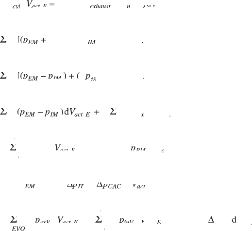
The pumping loss work is given by the integral of the p–V diagram in the
pumping strokes at 360–720° crank angle as follows (or represented by the
area enveloped by the p–V curve shown in Fig. 4.4 in Chapter 4):
360°
,
=
360°
72
0°
d
(
720
∞
Ú
d =d
pV
d pVd
pp
(pp (
cyl
pV
cyl
pV
ac
d
ac
d
pV
ac
pV
d pVd
ac
d pVd
tE
,tE,
d
tE
d
pp
exhaus
pp
ti
pp
ti
pp
– pp–
ti
– pp–
S
f
ntak
nntakn
ea
ntakeantak
ct
E
V
ea
V
ea
)d
ea
)d
ea
,
=D
D
=D =D
[(
=D[(=D
=D+ =D
)
– (
)]
d
=
360°
72
0°
S
=DS=D
f
pp
=Dpp=D
[(pp[(
=D[(=Dpp=D[(=D
=D+ =Dpp=D+ =D
pp
DppD
– (pp – (
– pp –
V
pp
EM
pp
=Dpp=D
EM
=Dpp=D
ex
pp
IM
pp
in
ac
V
ac
V
t
,,
E
=D
D
=D =D
[(
=D[(=D
)
=D) =D
=D+ =D
(
=D( =D
+
)]
d
=
360°
72
0°
S
=DS=D
f
pp
=Dpp=D
[(pp[(
=D[(=Dpp=D[(=D
=D– =Dpp=D– =D
pp
DppD
( pp(
=D( =Dpp=D( =D
+ pp+
V
pp
EM
pp
=Dpp=D
EM
=Dpp=D
IM
=D
IM
=D
pp
ex
pp
( pp(
ex
( pp(
in
ac
V
ac
V
t
,,
E
=D
=D =D
(–
)
d
360°
72
0°
,
=
SS
=DSS=D
=D(–=DSS=D(–=D
=D )=DSS=D )=D
=D(–=D )=D(–=DSS=D(–=D )=D(–=D
=Dd =DSS=Dd =D
ff
=
ff
=
360°
ff
360°
pp
(–pp(–
)pp )
(– )(–pp(– )(–
=D(–=DSS=D(–=Dpp=D(–=DSS=D(–=D
=D )=DSS=D )=Dpp=D )=DSS=D )=D
=D(–=D )=D(–=DSS=D(–=D )=D(–=Dpp=D(–=D )=D(–=DSS=D(–=D )=D(–=D
Vp
=DVp=D
d Vpd
,
Vp
,
=DSS=DVp=DSS=D
=Dd =DSS=Dd =DVp=Dd =DSS=Dd =D
=D+ =DSS=D+ =DVp=D+ =DSS=D+ =D
pp
EM
pp
(–pp(–
EM
(–pp(–
=D(–=DSS=D(–=Dpp=D(–=DSS=D(–=D
EM
=D(–=DSS=D(–=Dpp=D(–=DSS=D(–=D
IM
)
IM
)
=D )=DSS=D )=D
IM
=D )=DSS=D )=D
Vp
ac
Vp
d Vpd
ac
d Vpd
=Dd =DSS=Dd =DVp=Dd =DSS=Dd =D
ac
=Dd =DSS=Dd =DVp=Dd =DSS=Dd =D
Vp
tE
Vp
d Vpd
tE
d Vpd
,
Vp
,tE,
Vp
,
=Dd =DSS=Dd =DVp=Dd =DSS=Dd =D
tE
=Dd =DSS=Dd =DVp=Dd =DSS=Dd =D
EVO
EVC
ex
xV
exxVex
ac
tE
V
ac
V
ac
d
,
tE,tE
9.32
+D
D
+D +D
d
+
d
D dD
=
,
S
+DS+D
S
f
IV
O
IVOIV
IV
C
IVCIV
Va
d
Va
d
ct
d
ct
d
E
d
E
d
ValveClose
d
a
pV
d pVd
in
pV
in
Va
pV
Va
d
Va
d pVd
Va
d
pV
dpV d
D dDpVD dD
PM
pV
PM
d
PM
dpV d
PM
d
a
pV
a
ct
cctc
E
,
=
(
+
)d
=
360°
720°
2,
+
2,
+
2,
)d
2,
)d
S
f
pp
(pp (
– pp –
pp
2,
pp
2,
2,
pp
2,
V
2,
V
2,
pp
EM
pp
2,
pp
2,IT2,
pp
2,
2,
pp
2,
IT
2,
pp
2,
2,CA2,
2,Ca2,
)d
2,
)d
Ca
)d
2,
)d
2,
V
2,Ca2,
V
2,
2,ct2,
E
DD
+ DD+
2,
DD
2,
ppDDpp
+ pp+ DD+ pp+
2,
pp
2,
DD
2,
pp
2,
+
2,
+ pp+
2,
+ DD+
2,
+ pp+
2,
+
2,
pp
2,IT2,
pp
2,
DD
2,
pp
2,IT2,
pp
2,
+D
+D
+D +D
d
d
+D d+D
,
=
,
SS
+DSS+D
+DSS+D
d SSd
+Dd +DSS+Dd +D
ff
=
ff
=
ff
EVO
ff
EVC
ac
d
ac
d
d SSd
ac
d SSd
tE
d
tE
d
,tE,
d SSd
tE
d SSd
IV
O
IVOIV
IV
C
IVCIV
Va
ct
pV
d pVd
SSpVSS
d SSd pVd SSd
exV
pV
exV
SS
exV
SSpVSS
exV
SS
ac
pV
ac
d
ac
d pVd
ac
d
d SSd
ac
d SSd pVd SSd
ac
d SSd
pV
dpV d
in
pV
in
d
in
dpV d
in
d
Va
pV
Va
d
Va
dpV d
Va
d
EEE
ValveClose
d
ac
tE
pV
PM
pV
PM
ac
pV
ac
+
d
pV dpV
PM
pV
PM
d
PM
pV
PM
,
tE,tE
S
D
dD d
pV dpVDpV dpV
where p
cyl
is the in-cylinder pressure, V
act,E
is the total engine displacement of
the active cylinders, f is the crank angle, p
exhaust
and p
intake
are the in-cylinder
pressure during the exhaust and intake strokes, respectively; p
EM
and p
IM
are
the instantaneous exhaust and intake manifold pressures, respectively; Dp
ex
and Dp
in
are the pressure drops across the exhaust and intake valves/ports/
manifolds, respectively; Dp
exV
and Dp
inV
are the pressure drops across the
exhaust and intake valves during the valve opening events, respectively; and
Diesel-Xin-09.indd 587 5/5/11 11:59:11 AM
588 Diesel engine system design
© Woodhead Publishing Limited, 2011
Dp
PM
is the pressure losses in the intake and exhaust ports and manifolds
during the period of valve closure.
Equation 9.32 shows that the pumping loss is related not only to the intake
throttle pressure drop, but also to the valve ow pressure drops and the valve
opening duration (e.g., from IVO to IVC). The valve ow pressure drop is
related to the effective valve ow area. A larger valve ow area results in
a smaller pressure drop due to less restrictive ow. This is the reason why
the cam ow area needs to be maximized with aggressive cam acceleration.
When the valve ow area is small, volumetric efciency becomes low due
to high ow losses. The valve opening duration affects the amount of the
ow through the engine and thus also directly affects volumetric efciency.
If the valve event duration is too short, the mass ow rate will be too low in
equation 9.30 and thus the volumetric efciency will be low. Moreover, if the
valve event duration is too long, reverse ow will occur and the volumetric
efciency will also be low. More information on pumping loss denition on
the p-V diagram can be found in Shelby et al. (2004).
It should be noted that the intake manifold volumetric efciency is inherently
related only to the valvetrain and manifold designs. It is not affected by the
operation of intake throttle. When a VVA device with early IVC is used, the
volumetric efciency can become very low due to the very short intake valve
duration. However, the pumping loss can become very little if the intake
throttle is not closed, according to equation 9.32. In fact, this can be viewed
as an example of using an intake VVA to replace the intake throttle at the
part-load operation in a naturally aspirated gasoline engine. Although the
availability loss of throttling at the throttle valve itself is small, the resulting
engine pumping loss due to the throttling can be rather large. Therefore, in
principle any throttling in the engine is an indicator of high pumping loss
and should be avoided.
Pumping loss consists of two parts: the engine delta P (the rst term in
equation 9.32) and the ow restrictions related to volumetric efciency. The
second part can be further split into two portions: (1) the losses related to
valve event durations (the second and third terms in equation 9.32); and (2)
the losses associated with the ports and manifolds. Volumetric efciency
affects pumping loss differently via the valve ow restriction and the valve
event duration. If the valve ow area is too restrictive, the large pressure
drop across the valve results in a reduction in volumetric efciency and an
increase in pumping loss (i.e., expanding the pumping loss area shown in
Fig. 4.4 vertically). If the valve event duration is very short, the resulting low
volumetric efciency leads to a reduction in pumping loss (i.e., shrinking the
pumping loss area shown in Fig. 4.4 horizontally). The design modication
that reduces the ow restriction for a given valve ow duration (e.g., larger
valve ow area in a cam or VVA) results in an increase in volumetric
efciency and a decrease in the valve ow pumping loss. However, the
Diesel-Xin-09.indd 588 5/5/11 11:59:11 AM
589Advanced diesel valvetrain system design
© Woodhead Publishing Limited, 2011
designs affecting the valve event duration (e.g., cam or VVA timing) may
increase both volumetric efciency and the valve ow pumping loss. One
extreme example is that in cylinder deactivation the volumetric efciency
of the deactivated cylinders is zero and their pumping loss is also zero.
The link between valvetrain design and turbocharging is the intake
manifold pressure. Note that a higher volumetric efciency means a lower
intake manifold pressure and possibly less pumping loss because a lower
engine delta P can be created by a larger turbine area in order to reach the
same air ow requirement. Therefore, the net effect of valve timing change
on BSFC depends on the balance between the pumping losses caused by the
engine delta P and the valve ows.
Finally, it should be noted that BSFC (i.e., power loss) and engine gas
ow rate (i.e., volumetric efciency) are two independent different design
criteria (e.g., reected by the trade-off between BSFC and NO
x
) in valve
timing or VVA optimization. The topic can be a multi-objective optimization.
If achieving high ow rate is the design objective (e.g., for meeting emissions
or controlling the exhaust manifold gas temperature), different valve timing
designs need to be compared on volumetric efciency at the same intake
manifold pressure. On the other hand, if achieving low BSFC is the objective,
pumping losses need to be compared at the same engine ow rate.
9.7.5 Gasoline engine VVA performance
Overview of gasoline engine VVA
Before the discussion of diesel engine VVA performance, a summary of the
gasoline (spark ignition) engine VVA is benecial in order to understand
their differences. The majority of VVA research has been conducted at the
part-load conditions on the gasoline engine with the primary purposes of
eliminating or reducing the use of intake throttle, and optimizing the valve
timing to increase the volumetric efciency within a wide range of engine
speed to improve the low-speed torque. Both the port-fuel-injection and the
direct injection gasoline engines are partially throttled at part load to meet
the operational requirement of the exhaust aftertreatment catalyst. In this
case, VVA can replace the intake throttle to reduce fuel consumption. At the
full load, the engine is usually run with the intake throttle fully open.
Over the next few decades the following three technologies will have
decisive impacts on the gasoline engine in air ow controls to improve fuel
economy: (1) throttleless operation by using VVA to achieve charge control
or load control to replace the intake throttle; (2) stratication by direct
injection; and (3) variable displacement by cylinder deactivation.
Important research work on gasoline engine VVA performance has been
conducted by Tuttle (1980), Elrod and Nelson (1986), Ma (1988), Payri et
al. (1988), Saunders and Abdul-Wahab (1989), Ahmad and Theobald (1989),
Diesel-Xin-09.indd 589 5/5/11 11:59:11 AM