Xin Q. Diesel Engine System Design
Подождите немного. Документ загружается.

550 Diesel engine system design
© Woodhead Publishing Limited, 2011
thermodynamic cycle performance to achieve an on-target valvetrain
vibration level matched with the no-follow speed target with the maximum
cam acceleration
∑ acceptable valve seating velocity and noise through cam profile
design
∑ optimized cam base circle diameter, roller diameter, rocker arm ratio,
and maximum valve lift
∑ acceptable minimum cam radius of curvature for cam manufacturing
∑ acceptable maximum pushrod force without pushrod buckling and
exceeding the limit of valvetrain joint strength
∑ acceptable cam stress and oil lm thickness
∑ minimum valve tip scrub achieved by optimum kinematic layout
∑ low friction and wear achieved by good kinematics, dynamics and
appropriate valve spring force
∑ no valve spring surge or coil clash/bind by designing low cam harmonic
amplitudes and appropriate valve spring design.
The heart of the valvetrain design is the cam prole, which is critical for
both engine breathing performance and valvetrain dynamics. It should
be noted that the design of the OHC valvetrain with the end-pivot nger
follower is more complex than that of the pushrod valvetrain due to its
two-dimensional oscillating follower motion rather than the simpler one-
dimensional translational follower motion. The calculation methods of cam
radius of curvature for the pushrod cam and the nger follower OHC are
also different.
9.2 Effect of valve timing on engine performance
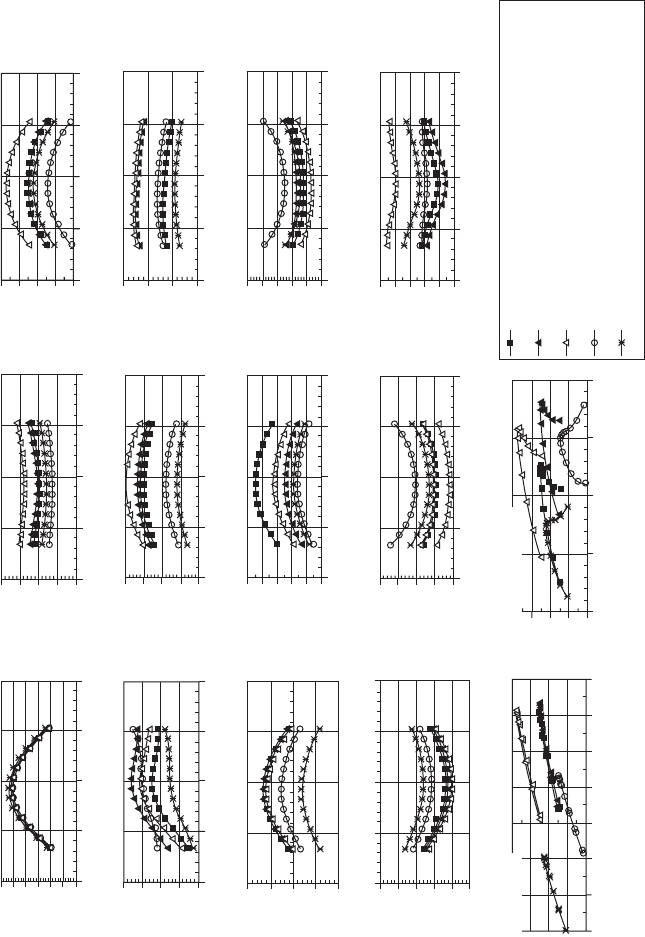
The effect of valve timing on engine performance is illustrated in the
simulation results of Figs 9.8–9.10 for a light-duty EGR diesel engine. The
optimum selection of the IVO, IVC, and EVC timing is usually based on
both volumetric efciency and BSFC. The optimum selection of the EVO is
usually based on BSFC. Note that the optimum valve timing is a trade-off
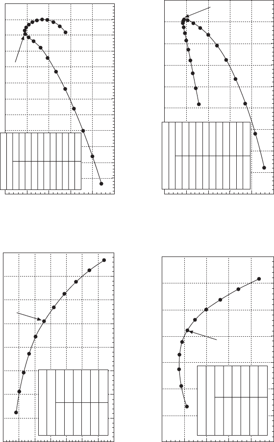
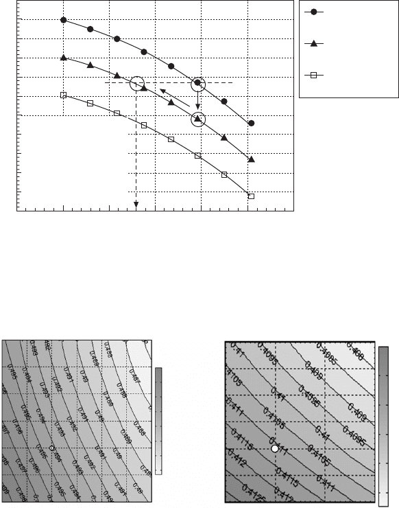
between high speeds and low speeds. Another typical method to analyze
the optimum valve timing is shown in Fig. 9.11 by plotting the volumetric
efciency at a high speed vs. that at a low speed. In this way, the trade-off
behavior of engine valve timing between high speeds and low speeds can be
illustrated clearly to facilitate a design decision on the air ow capability.
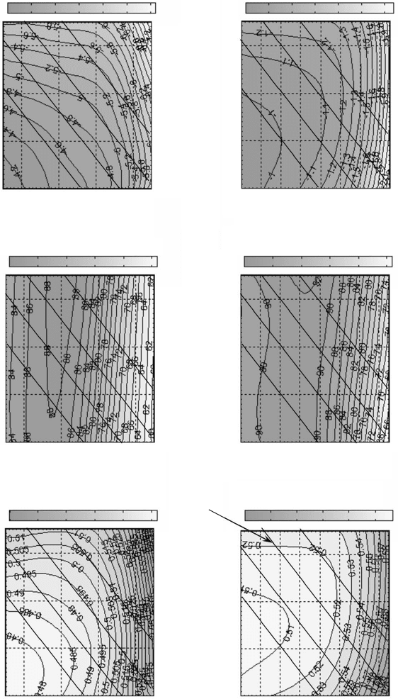
Figure 9.12 illustrates the effects of valve overlap size and IVC timing for
a heavy-duty non-EGR diesel engine that uses a large turbine area to achieve
negative engine delta P at peak torque. The simulation data show that when
the intake manifold pressure is higher than the exhaust manifold pressure, the
larger valve overlap reduces the exhaust manifold gas temperature at peak
Diesel-Xin-09.indd 550 5/5/11 11:58:54 AM
551Advanced diesel valvetrain system design
© Woodhead Publishing Limited, 2011
torque. In contrast, at rated power where the exhaust manifold pressure is
higher than the intake manifold pressure, larger valve overlap results in an
increase in the exhaust reverse ow (residue) and a reduction in air–fuel ratio
and hence an increase in the exhaust manifold gas temperature. Note that
the valve overlap also has an impact on engine delta P due to the variation
in volumetric efciency. Such an interaction can be explained by the core
theoretical formula of the engine air system shown in Chapter 4. Figure
9.12(c) analyzes the interaction between IVC timing and turbocharging, and
is explained in detail in Section 9.7.
The IVC timing affects the effective compression ratio and the cold-start
capability of the engine. Figure 9.13 illustrates the effects of the IVC timing
and engine geometric compression ratio on cold-start capability.
Figure 9.14 presents a sensitivity analysis about the effect of engine
valve size on BSFC at a typical low speed and high speed. The analysis
shows that at 2000 rpm 30% load, the BSFC is much more sensitive to the
change in intake valve diameter (i.e., 0.65% BSFC reduction for every 1 mm
increase in diameter) than the change in exhaust valve diameter (i.e., 0.29%
BSFC reduction for every 1 mm increase). However, at 3000 rpm full load,
the BSFC is more sensitive to the change in exhaust valve diameter (i.e.,
0.24% BSFC reduction for every 1 mm increase) than the change in intake
valve diameter (i.e., 0.21% BSFC reduction for every 1 mm increase). This
indicates that the size of the exhaust valve becomes more important at high
speeds where the exhaust manifold pressure and pumping loss are high.
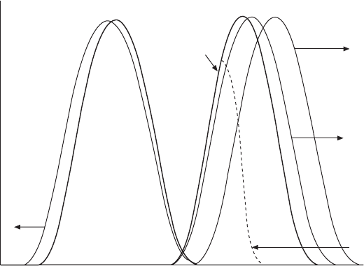
9.8 Illustration of valve timing changes in parametric simulation of
engine breathing.
Kinematic valve lift
EVO
advance
IVC
retard
Intake valve
timing (IVO and
IVC) shifted
‘Lost motion’
early IVC, stretch
of both duration
and maximum
valve lift
Crank angle
Intake
Exhaust
Baseline
valve lift
profile
Diesel-Xin-09.indd 551 5/5/11 11:58:54 AM

© Woodhead Publishing Limited, 2011
320 340 360 380
IVO (degree crank angle)
320 340 360 380
IVO (degree crank angle)
320 340 360 380
IVO (degree crank angle)
320 340 360 380
IVO (degree crank angle)
320 340 360 380
IVO (degree crank angle)
320 340 360 380
IVO (degree crank angle)
IVC (degree crank angle)IVC (degree crank angle)
IVC (degree crank angle)IVC (degree crank angle)
IVC (degree crank angle)IVC (degree crank angle)
620
600
580
560
540
620
600
580
560
540
620
600
580
560
540
620
600
580
560
540
620
600
580
560
540
620
600
580
560
540
Along each line, cam
duration is same.
BSFC (lb/(hp.hr))
BSFC (lb/(hp.hr))
Intake manifold
mixture vol. effi. (%)
Intake manifold
mixture vol. effi. (%)
Gross pumping
loss PMEP (bar)
Gross pumping loss
PMEP (bar)
54.6 hp 2000 rpm,
IVO-IVC
270 hp 3600 rpm,
IVO-IVC
270 hp 3600 rpm,
IVO-IVC
54.6 hp 2000 rpm,
IVO-IVC
270 hp 3600 rpm,
IVO-IVC
54.6 hp 2000 rpm,
IVO-IVC
0.51
0.5
0.49
0.48
0.47
0.46
0.58
0.56
0.54
0.52
0.5
85
80
75
70
92
90
88
86
84
82
80
78
76
–1
–1.2
–1.4
–1.6
–1.8
–2
–3.5
–4
–4.5
–5
–5.5
9.9 Intake valve timing effect at high speed (3600 rpm) and low speed (2000 rpm) of a LD diesel engine.
Diesel-Xin-09.indd 552 5/5/11 11:58:55 AM
© Woodhead Publishing Limited, 2011
100 120 140 160
EVO (degree crank angle)
100 120 140 160
EVO (degree crank angle)
100 120 140 160
EVO (degree crank angle)
100 120 140 160
EVO (degree crank angle)
100 120 140 1600
EVO (degree crank angle)
100 120 140 160
EVO (degree crank angle)
EVC (degree crank angle)
EVC (degree crank angle)
EVC (degree crank angle)EVC (degree crank angle)
EVC (degree crank angle)
EVC (degree crank angle)
400
380
360
340
410
400
390
380
370
360
350
340
400
380
360
340
410
400
390
380
370
360
350
340
400
380
360
340
410
400
390
380
370
360
350
340
Along each line, cam
duration is same.
BSFC (lb/(hp.hr))
BSFC (lb/(hp.hr)) Intake manifold mixture
vol. effi. (%)
Intake manifold
mixture vol. effi. (%)
Gross pumping
loss PMEP (bar)
Gross pumping loss
PMEP (bar)
54.6 hp 2000 rpm,
EVO-EVC
270 hp 3600 rpm,
EVO-EVC
270 hp 3600 rpm,
EVO-EVC
54.6 hp 2000 rpm,
EVO-EVC
270 hp 3600 rpm,
EVO-EVC
54.6 hp 2000 rpm,
EVO-EVC
0.58
0.56
0.54
0.52
0.5
0.48
0.62
0.6
0.58
0.56
0.54
0.52
85
80
75
70
65
60
90
85
80
75
70
65
–1
–1.2
–1.4
–1.6
–1.8
–2
–2.2
–4.5
–5
–5.5
–6
–6.5
–7
–7.5
9.10 Exhaust valve timing effect at high speed (3600 rpm) and medium speed (2000 rpm) of a LD diesel engine.
Diesel-Xin-09.indd 553 5/5/11 11:58:55 AM
© Woodhead Publishing Limited, 2011
Intake manifold volumetric
efficiency of air+EGR mixture at
4000 rpm full load (rated)
Intake manifold volumetric
efficiency of air+EGR mixture at
4000 rpm full load (rated)
Intake manifold volumetric
efficiency of air+EGR mixture at
4000 rpm full load (rated)
Intake manifold volumetric
efficiency of air+EGR mixture at
4000 rpm full load (rated)
93%
92%
91%
90%
89%
88%
87%
86%
91.0%
90.5%
90.0%
89.5%
89.0%
88.5%
95%
90%
85%
80%
75%
70%
95%
90%
85%
80%
75%
70%
Effect of IVC timing
Effect of IVO timing
Effect of valve overlap duration
Effect of EVC timing
83% 84% 85% 86% 87% 88% 89% 90% 91%
Intake manifold volumetric efficiency of air+EGR
mixture at 1000 rpm full load
86.0% 86.5% 87.0% 87.5% 88.0% 88.5% 89.0% 89.5%
Intake manifold volumetric efficiency of air+EGR
mixture at 1000 rpm full load
80% 81% 82% 83% 84% 85% 86% 87% 88% 89%
Intake manifold volumetric efficiency of air+EGR
mixture at 1000 rpm full load
78% 79% 80% 81% 82% 83% 84% 85% 86% 87% 88% 89% 90%
Intake manifold volumetric efficiency of air+EGR
mixture at 1000 rpm full load
Current
Current
Current
Current
Valve overlap = EVC – IVO
A
A
A
B
B
B
A
B
From A to B
From A to B
From A to B
From A to B
IVC (deg)
Valve overlap (deg)
EVC (deg)
IVO (deg)
613.8
610.9 596.4
608.0 593.5
605.1 590.6
602.2 587.7
599.3 584.8
90.10
84.36 26.96
78.62 21.22
72.88 15.48
67.14 9.74
61.40 4.00
55.66 –1.74
49.92 –7.48
44.18 –13.22
38.44 –18.96
32.70 –24.70
403.20
400.28 371.08
397.36 368.16
394.44 365.24
391.52 362.32
388.60 359.40
385.68 356.48
382.76 353.56
379.84 350.64
376.92 347.72
374.00 344.80
327.20
330.02 344.12
332.84 346.94
335.66 349.76
338.48 352.58
341.30 355.40
9.11 Valve timing trade-offs of a LD diesel engine between high speed (4000 rpm) and low speed (1000 rpm).
Diesel-Xin-09.indd 554 5/5/11 11:58:55 AM

© Woodhead Publishing Limited, 2011
9.12 Effects of valve overlap (a) and IVC timing (b) and (c) on the performance of a non-EGR diesel engine.
–100 –50 0 50 100 150 200
Valve overlap (EVC-IVO, degree)
–100 –50 0 50 100 150 200
–100 –50 0 50 100 150 200
Valve overlap (EVC-IVO, degree)
–100 –50 0 50 100 150 200
Valve overlap (EVC-IVO, degree)
–100 –50 0 50 100 150 200
Valve overlap (EVC-IVO, degree)
–100 –50 0 50 100 150 200
Valve overlap (EVC-IVO, degree)
Valve overlap (EVC-IVO, degree)
(a)
(b)
2100
2050
2000
1950
1900
1060
1040
1020
1000
980
Peak cylinder
temperature (K)
Exhaust manifold
gas temperature (K)
500 550 600 650 700
IVC timing (degree)
500 550 600 650 700
IVC timing (degree)
500 550 600 650 700
IVC timing (degree)
500 550 600 650 700
IVC timing (degree)
500 550 600 650 700
IVC timing (degree)
500 550 600 650 700
IVC timing (degree)
Intake manifold
trapped volumetric
efficiency
Intake manifold
trapped volumetric
efficiency
Engine delta P
(bar)
1
0.8
0.6
0.4
0.2
0
0.5
0
–0.5
–1
–1.5
–2
0.5
0
–0.5
–1
–1.5
–2
4.0
3.5
3.0
2.5
2.0
200
190
180
170
160
2500
2300
2100
1900
1700
25
20
15
10
5
0
25
20
15
10
5
0
22
21
20
19
18
70%
65%
60%
55%
50%
45%
4
3
2
1
0
49%
48%
47%
46%
45%
0.45
0.43
0.41
0.39
0.37
0.35
4.0
3.5
3.0
2.5
2.0
BSFC (lb/(hp.hr))
BSFC (lb/(hp.hr))
Exhaust manifold
P (bar, absolute)
Exhaust manifold
P (bar, absolute)
A/F ratioA/F ratio
Intake manifold
P (bar,
absolute)
Intake manifold P
(bar, absolute)
Peak torque (2000 rpm) Rated power (3400 rpm)
Residual gas
fraction (internal
EGR, %)
Turbo charger
efficiency
Residual gas fraction
(internal EGR, %)
Turbo charger
efficiency
Engine delta P
(bar)
Gross pumping
loss PMEP (bar)
Gross pumping
loss PMEP (bar)
Peak cylinder P
(bar, absolute)
Peak cylinder P
(bar, absolute)
Peak cylinder
temperature (K)
Exhaust manifold
gas temperature
(K)
0.9
0.8
0.7
0.6
0.5
4.0
3.8
3.6
3.4
3.2
3.0
200
190
180
170
160
0
–0.5
–1
–1.5
–2
4.0
3.8
3.6
3.4
3.2
3.0
0.395
0.390
0.385
0.380
0.375
0.8
0.6
0.4
0.2
0
At rated power 3400 rpm
1100
1000
900
800
700
600
Diesel-Xin-09.indd 555 5/5/11 11:58:56 AM
© Woodhead Publishing Limited, 2011
500 550 600 650 700
IVC timing (degree)
500 550 600 650 700
IVC timing (degree)
500 550 600 650 700
IVC timing (degree)
500 550 600 650 700
500 550 600 650 700
IVC timing (degree)
500 550 600 650 700
IVC timing (degree)
500 550 600 650 700
IVC timing (degree)
500 550 600 650 700
IVC timing (degree)
500 550 600 650 700
IVC timing (degree)
500 550 600 650 700
IVC timing (degree)
500 550 600 650 700
IVC timing (degree)
500 550 600 650 700
IVC timing (degree)
Intake manifold
trapped volumetric
efficiency
IVC timing (degree)
Air system capability Air system capability
24
22
20
18
16
22
20
18
16
A/F ratio
A/F ratio
–0.6 –0.4 –0.2 0 0.2 0.4 0.6 0.8
Engine delta P (bar)
0.370 0.375 0.380 0.385 0.390
BSFC (lb/hp.hr)
(c)
Turbine area = 0.9, wastegate = 16 mm, CR = 20,
compressor and turbine map efficiency multipliers = 1
Turbine area = 0.9, wastegate = 16 mm, CR = 16.5,
compressor and turbine map efficiency multipliers = 1
Turbine area = 0.9, wastegate = 16 mm, CR = 16.5,
compressor and turbine map efficiency multipliers = 1.05
Turbine area = 0.9, wastegate = 21 mm, CR = 16.5,
compressor and turbine map efficiency multipliers = 1
Turbine area = 1.2, wastegate = 16 mm, CR = 16.5,
compressor and turbine map efficiency multipliers = 1
90%
85%
80%
75%
70%
65%
60%
0.390
0.385
0.380
0.375
0.370
1
0.5
0
–0.5
–1
0
–0.5
–1
–1.5
–2
–2.5
BSFC
(lb/(hp.hr))
Engine delta
P (bar)
Gross pumping
loss PMEP (bar)
4.0
3.5
3.0
2.5
2.0
24
22
20
18
16
4.0
3.5
3.0
2.5
1150
1100
1050
1000
950
900
55%
53%
51%
49%
47%
45%
4.0
3.5
3.0
2.5
2.0
240
220
200
180
160
140
2200
2100
2000
1900
1800
Intake manifold
pressure (bar,
absolute)
Exhaust manifold
pressure (bar,
absolute)
Peak cylinder
pressure (bar,
absolute)
Peak cylinder
temperature
(K)
A/F ratio
Residual gas
fraction (internal
EGR rate, %)
Turbocharger
efficiency
Exhaust manifold
gas temperature (K)
9.12 Continued
Diesel-Xin-09.indd 556 5/5/11 11:58:56 AM
557Advanced diesel valvetrain system design
© Woodhead Publishing Limited, 2011
9.3 Valvetrain dynamic analysis
The simplest valvetrain dynamic analysis is the cam harmonic analysis
to convert the cam acceleration or cam lift proles from the time domain
(or the crank angle domain) to the frequency domain without the need for
using a valvertain dynamics model. The harmonic analysis is an effective
and convenient method to compare the relative difference in the dynamic
excitation source for the valvetrain, and can be used in cam design to judge
the quality and the aggressiveness of the cam acceleration shape. The
Compression
ratio = 18
Compression
ratio = 17
Compression
ratio = 16
Note:
Zero degree is the
firing TDC.
If CR decreases
from 18 to 17 to
control peak cylinder
pressure at rated,
IVC needs to be
advanced from 599°
to 586° in order to
maintain the original
cold-start capability.
560 570 580 590 600 610 620
IVC timing (degree crank angle)
730
720
710
700
690
680
670
660
650
640
630
620
Maximum cylinder air temperature
near compression TDC (°F)
Exhaust valve diameter (mm)
Exhaust valve diameter (mm)
31.5
31
30.5
30
29.5
29
28.5
31.5
31
30.5
30
29.5
29
28.5
0.498
0.496
0.494
0.492
0.49
0.488
0.486
0.413
0.412
0.411
0.41
0.409
0.408
33 33.5 34 34.5 35 35.5 36
Intake valve diameter (mm)
33 34 35 36
Intake valve diameter (mm)
2000 rpm 30% load,
simulation at fixed emissions
BSFC (lb/(hp.hr))
3000 rpm rated power,
simulation at fixed emissions
BSFC (lb/(hp.hr))
9.13 Effect of IVC timing and engine compression ratio on cold-start
performance at 100 rpm cranking in –10°F cold ambient.
9.14 Effect of engine valve size on BSFC.
Diesel-Xin-09.indd 557 5/5/11 11:58:57 AM
558 Diesel engine system design
© Woodhead Publishing Limited, 2011
amplitudes of the harmonics indicate the energy contents of the harmonics.
Both harmonic amplitude and harmonic number are important in determining
the dominant harmonics of the cam acceleration as a source of vibration
excitation for the valvetrain and valve spring surge. The harmonic peaks around
approximately the 13th harmonic are important indicators of the tendency
for valve spring surge. The higher the peaks, the greater the tendency is.
A cam that possesses a good acceleration shape and induces low vibration
usually has low harmonic amplitudes. An example of cam harmonic analysis
is shown later in Fig. 9.18 in the section on cam design. More information
about the frequency analysis of valvetrain vibrations is provided in Norton
et al. (1998) and Grönlund and Larmi (2004).
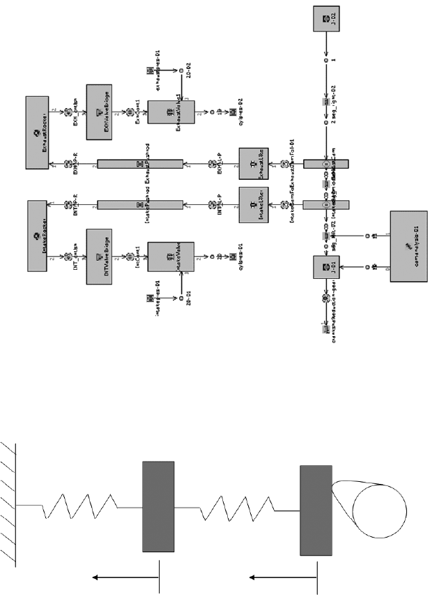
Valvetrain dynamics modeling has been motivated by the following two
needs: designing the cam and predicting the dynamic response of each
valvetrain component. There are generally two types of valvetrain dynamics
models (Fig. 9.15): the single-degree-of-freedom model, and the multi-
body dynamics model. The single-degree-of-freedom model is a lumped
simplication of the valvetrain system by lumping the component masses
to a valvetrain equivalent mass and lumping the component stiffness to an
overall valvetrain stiffness (Jensen, 1987). The damping and gas loading
effects are ignored in the model. Moreover, the model is only valid for
the congurations that have one-dimensional translational motion, such as
the pushrod valvetrain and the direct-acting OHC valvetrain. The single-
degree-of-freedom model can be used to output the Polydyne cam lift prole
(Jensen, 1987; Thoren et al., 1952; Stoddart, 1953). The Polydyne cam lift
prole is computed based on a prescribed input of a smooth non-vibratory
dynamic valve lift prole at a ‘design speed’. At other engine speeds, the
model outputs vibratory dynamic valve lift proles.
Although the multi-body dynamics model does not have the simplication
or restrictions mentioned above, the model only uses cam prole as an input
and does not have the ability to output a cam design. An advanced integrated
approach requires using the single-degree-of-freedom model to conduct
Polydyne cam prole design and then using the multi-body dynamics model
to check the dynamic response of the cam by considering the sophisticated
effects such as the stiffness and damping of each individual component, gas
loading, and the dynamic behavior of the hydraulic lash adjuster (if any). Note
that recompression pressure control is especially important for the valvetrain
dynamics of modern diesel engines. The recompression pressure analysis is
rst conducted with a cycle simulation model (e.g., GT-POWER) and then
the result is input into the multi-body valvetrain dynamics model.
Typical simulation results of valvetrain dynamics are show in Fig. 9.16.
At low engine speeds, the pushrod force (or cam force) is dominated by the
valve spring force because the dynamic inertia force is low. At high speeds,
the vibratory valve acceleration force becomes prominent, and therefore the
Diesel-Xin-09.indd 558 5/5/11 11:58:57 AM
© Woodhead Publishing Limited, 2011
Valve lift
Valve spring
Valvetrain stiffness
GT-VTRAIN valvetrain dynamics model layout
Valvetrain
equivalent mass
Cam lift
Cam
(a) Single-degree-of-freedom model (b) Multi-body dynamics model (GT-VTRAIN)
Follower mass
Intake rocker
Intake valve
bridge
Intake port
pressure gas
load
Exhaust port
pressure gas
load
Exhaust
valve bridge
Exhaust rocker
Intake
pushrod
Exhaust
pushrod
Intake valve
Intake cam Exhaust cam
Intake
follower
Exhaust
follower
Cylinder pressure
gas load
Cylinder pressure
gas load
Exhaust valve
9.15 Illustration of valvetrain dynamics models.
Diesel-Xin-09.indd 559 5/5/11 11:58:57 AM