Xin Q. Diesel Engine System Design
Подождите немного. Документ загружается.

560 Diesel engine system design
© Woodhead Publishing Limited, 2011
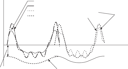
pushrod force exhibits an oscillatory pattern within the cam event cycle.
Figure 9.16 also illustrates the valve spring deceleration, which is equal to
the spring force divided by the valvetrain equivalent mass. The intersection
of the spring deceleration on the vertical axis corresponds to the spring
preload, and the slope of the spring deceleration curve corresponds to the
spring rate. Once the valve acceleration and spring deceleration cross over,
valvetrain no-follow occurs. The appropriate choices of valve spring preload
and spring rate can be analyzed by visually examining the relative difference
between the valve acceleration and the spring deceleration as shown in Fig.
9.16.
The scope of valvetrain dynamics not only includes the evaluation
of the valvetrain vibration forces within a cam event cycle (i.e., single-
cylinder valvetrain dynamics), but also includes the torsional vibration and
the dynamic bearing forces of the camshaft (i.e., multi-cylinder valvetrain
dynamics). The single-cylinder valvetrain dynamics simulation is presented
by Johnson (1962), Dennis and Neuser (1966), Akiba et al. (1981), Pisano
and Freudenstein (1983a, 1983b) Pisano (1984, 1986), Chan and Pisano
(1987), Akiba and Kakiuchi (1988), Kurisu et al. (1991), Hellinger et
al. (1992), Gast and David (1996), Keribar (2000), Iritani et al. (2002),
Grönlund and Larmi (2004), Ito (2006), and Xu et al. (2007). The dynamic
modeling of the multi-cylinder valvetrain and camshaft system is detailed by
Reinicke-Murmann and Kreuter (1990), Roß and Arnold (1993), Okamura
and Yamashita (1997), Stout (1997), Speckens et al. (1999), Du and Chen
(2000), Takagishi et al. (2004), and Londhe et al. (2009).
Exhaust and intake valve acceleration and valve spring deceleration simulation
2600 rpm, exhaust valvetrain, motoring
3000 rpm, exhaust valvetrain, motoring
2600 rpm, intake valvetrain, full load
3000 rpm, intake valvetrain, full load
Exhaust
valvetrain
vibration
Corresponding to
valve spring preload
Intake
valvetrain
vibration
Valve acceleration
Crank angle
The slope of the valve spring deceleration
curve reflects valve spring rate.
9.16 Valvetrain dynamics simulation.
Diesel-Xin-09.indd 560 5/5/11 11:58:57 AM
561Advanced diesel valvetrain system design
© Woodhead Publishing Limited, 2011
9.4 Cam profile design
9.4.1 Valvetrain system parameters in cam design
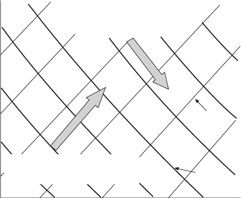
Before the cam lobe prole is designed, several system-level parameters need
to be determined as the input data to be used in cam design: maximum valve
lift, rocker arm ratio, maximum cam lift, maximum allowable cam stress,
no-follow speed, and minimum allowable cam radius of curvature (ROC).
Their relationship is illustrated in Fig. 9.17. The radius of curvature is further
related to cam base circle radius and the roller radius of the follower.
9.4.2 Impact of cam profile on valvetrain dynamics
The bad design of using discontinuous or non-smooth shape of cam
acceleration and jerk should always be avoided simply because they are not
optimized from a valvetrain dynamics point of view. Good cam design is a
trade-off between the valve ow area and valvetrain vibration. It is an on-
target design to achieve the allowable maximum cam stress and no-follow
speed target by properly selecting the maximum cam lift and designing the
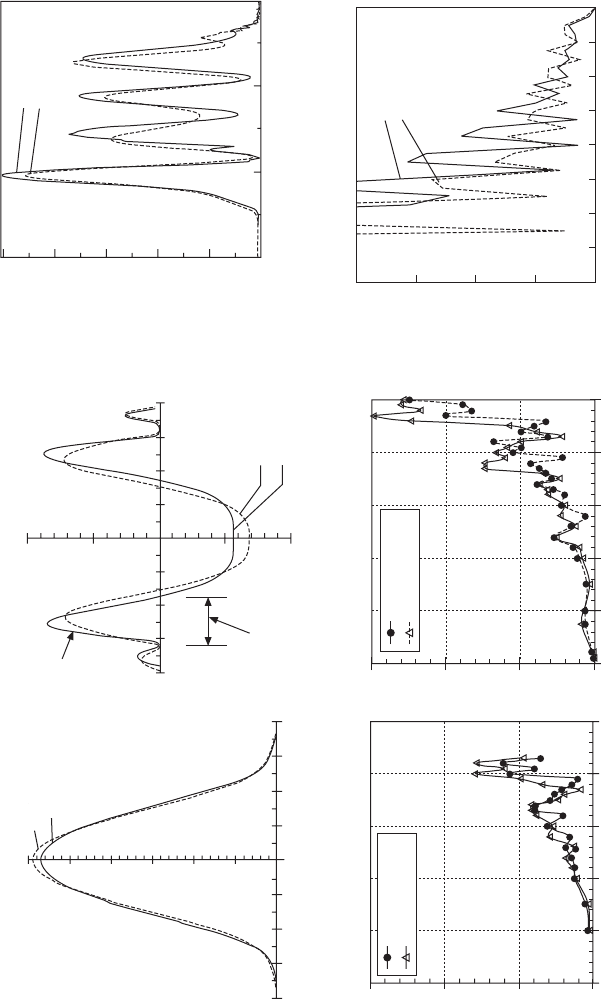
cam acceleration shape. Figure 9.18 illustrates the cam design results of two
intake cam lobe proles for a pushrod valvetrain. The intake cam A is the
design that satises the no-follow requirement. Although the intake cam B
provides more valve ow area at the cam anks due to its more aggressive
cam acceleration prole, it produces unacceptable no-follow conditions
For the thinner curves, this direction
is decreasing maximum cam lift and
increasing cam radius of curvature
Maximum valve lift
For the thicker curves, this direction
is decreasing no-follow speed and
increasing maximum cam stress
Constant
no-follow
speed
Constant
maximum
cam lift
Rocker arm ratio
9.17 Parametric design chart for cam design.
Diesel-Xin-09.indd 561 5/5/11 11:58:58 AM
© Woodhead Publishing Limited, 2011
Cam acceleration harmonic amplitude
Pushrod load (lbs) (¥10
–3
)
Valvetrain dynamic simulation at 4400 rpm
motoring with 100 psi recompression pressure
Intake cam acceleration harmonic analysis at 4400
rpm, camshaft frequency 36.7Hz, 32-order graph
0.065 0.070 0.075
Time (sec)
Intake cam B
Intake cam A
Intake cam B
Intake cam A
Intake cam A
Intake cam B
Intake cam A
Intake cam B
Intake cam A
Intake cam B
0 147 293 440 587 733 880 1027 1173
Frequency (Hz)
0.000500
0.000375
0.000250
0.000125
0.000000
3
2
1
0
6
5
4
3
2
1
0
3
2
1
0
0.01
0.005
0
–0.005
–0.01
1.0
0.8
0.6
0.4
0.2
0.0
Valve seating velocity (m/sec)
Valve seating velocity (m/sec)
Cam acceleration (mm/
cam degree
2
)
0 1000 2000 3000 4000 5000
Engine speed (rpm)
0 1000 2000 3000 4000 5000
Engine speed (rpm)
Cam tappet lift (mm)
–80 –60 –40 –20 0 20 40 60 80
Cam angle (degree)
–80 –60 –40 –20 0 20 40 60 80
Cam angle (degree)
This slope and
height control
pushrod force
peak
This width
controls valvetrain
no-follow
Intake cam B
Intake cam A
Intake valve seating velocity
simulation at full load
Intake valve seating velocity
simulation at motoring
9.18 Cam design comparison and impact on valvetrain dynamics.
Diesel-Xin-09.indd 562 5/5/11 11:58:58 AM

563Advanced diesel valvetrain system design
© Woodhead Publishing Limited, 2011
and higher valve seating velocities than the intake cam A. Note that the
intake cam A has lower harmonic amplitudes than the cam B in the cam
acceleration harmonic analysis. This difference in the excitation source of
the valvetrain directly correlates to the difference in the pushrod vibration
forces simulated.
9.4.3 Dynamic cam design
In general there are two categories of methods for cam lobe design: dynamic
and static (kinematic). In the kinematic design method, the cam lift pro le
is obtained by analytically solving the kinematic equations or numerically
integrating twice from a prescribed cam acceleration pro le, and then a
valvetrain dynamics model can be used to check whether the cam lift pro le
gives satisfactory dynamic response. In the dynamic design method, the cam
lift pro le is obtained by solving the equations of single-degree-of-freedom
valvetrain dynamics (Fig. 9.15) for a prescribed target pro le of the dynamic
valve lift at a given (selected) ‘design speed’. The cam pro le obtained by
the dynamic method can be checked for valvetrain dynamic response at other
speeds by using either a single-degree-of-freedom model or a more accurate
multi-body valvetrain dynamics model.
The most widely used dynamic cam design method is the Polydyne theory
established by Stoddart (1953). In the Polydyne method, there is an engine
speed at which the valvetrain vibration amplitude induced by the cam pro le
becomes zero theoretically, resulting in a smooth and non-vibratory valve
lift pro le under the dynamic inertia effect. This unique speed is called the
‘design speed’ of the cam. Although based on a simpli ed single-degree-
of-freedom dynamic model, the Polydyne method does offer two superior
advantages compared with the static cam design approach where any dynamic
effect cannot be accounted for directly in the cam pro le design. First, the
Polydyne method allows the designer to specify a desired target dynamic
valve lift pro le at the design speed as the cam design input, and then
calculate the corresponding cam pro le based on the knowledge of valvetrain
weight, stiffness, rocker ratio, etc. The cam pro le is assembled from the
motion desired at the valve and the de ections caused by the spring force
and the inertia force. Secondly, the method uses a single-piece polynomial
to de ne the valve lift pro le at the design speed for the entire valve event
(also called the main cam event) so that the higher-order derivatives of the
cam lift pro le (i.e., cam acceleration and jerk) can be continuous and much
smoother than the multi-piece polynomial cam pro le.
The valve motion in the single-degree-of-freedom model can be expressed
as
ml
Kl
KK
l
VT
ml
VT
ml
VAL
sV
Kl
sV
Kl
TC
Kl
TC
Kl
sVTCsV
Kl
sV
Kl
TC
Kl
sV
Kl
AM
TCAMTC
eq
sV
KK
sV
KK
Ts
KK
Ts
KK
sVTssV
KK
sV
KK
Ts
KK
sV
KK
SP
VAL
=
– (
KK +KK
KK
Ts
KK +KK
Ts
KK
)
KK )KK
Ts
)
Ts
KK
Ts
KK )KK
Ts
KK
SP
)
SP
,,
sV,,sV
TC,,TC
sVTCsV,,sVTCsV
AM,,AM
TCAMTC,,TCAMTC
,,
sV,,sV
Ts,,Ts
sVTssV,,sVTssV
)
,,
)
Ts
)
Ts,,Ts
)
Ts
9.5
Diesel-Xin-09.indd 563 5/5/11 11:58:58 AM
564 Diesel engine system design
© Woodhead Publishing Limited, 2011
where m
VT
is the valvetrain equivalent mass, l
VAL
is the dynamic valve lift
as a function of cam angle,
l
VAL
is the valve acceleration, l
CAM,eq
is the
equivalent cam lift at the valve side as a function of cam angle beyond the
cam ramps, K
s,VT
is the valvetrain stiffness, and K
s,SP
is the valve spring
stiffness (i.e., spring rate). Equation 9.5 can be rewritten as follows for the
valve motion:
fl
fl
l
fl
dd
fl
VAL
fl
sd
fl
VAL
CA
Me
q
+
=
,
Me,Me
9.6
where f
dd
is the dynamic de ection factor, f
dd
= m
VT
/K
s,VT
; and f
sd
is the static
de ection factor, f
sd
= (K
s,VT
+ K
s,SP
)/K
s,VT
. Once the cam lift is known,
the valve lift can be solved analytically with equation 9.6 at each engine
speed. The concept of the Polydyne cam design is to prescribe a desired
smooth valve lift pro le without any vibration at a selected engine speed, the
design speed, and compute the cam lift pro le by using equation 9.6 at the
design speed. At any other speeds, the dynamic valve lift pro le calculated
by equation 9.6 would be non-smooth or vibratory.
The desired valve lift pro le can be assumed in the form of a polynomial
as
lC
CC
C
VAL
lC
VAL
lC
lC
de
lC
gn
MC
AM
MCAMMC
nC
AM
nCAMnC
n
,0
lC
,0
lC
de,0de
lC
de
lC
,0
lC
de
lC
si,0si
lC
si
lC
,0
lC
si
lC
gn,0gn
lC
gn
lC
,0
lC
gn
lC
12
CC
12
CC
2
lC= lC
lC
,0
lC= lC
,0
lC
+
+
CC +CC
CC
12
CC +CC
12
CC
MC
MC
AM
AM
MCAMMC
MCAMMC
+ … +
ff
CC
ff
CC
CA
ff
CA
MC
ff
MC
12
ff
12
CC
12
CC
ff
CC
12
CC
CA12CA
ff
CA12CA
CC
CA
CC
12
CC
CA
CC
ff
CC
CA
CC
12
CC
CA
CC
MC12MC
ff
MC12MC
CC
MC
CC
12
CC
MC
CC
ff
CC
MC
CC
12
CC
MC
CC
2
ff
2
CC +CC
ff
CC +CC
CC
12
CC +CC
12
CC
ff
CC
12
CC +CC
12
CC
CC
CA
CC
12
CC
CA
CC +CC
CA
CC
12
CC
CA
CC
ff
CC
CA
CC
12
CC
CA
CC +CC
CA
CC
12
CC
CA
CC
CC
MC
CC
12
CC
MC
CC +CC
MC
CC
12
CC
MC
CC
ff
CC
MC
CC
12
CC
MC
CC +CC
MC
CC
12
CC
MC
CC
MC
MC
ff
MC
MC
MC12MC
MC12MC
ff
MC12MC
MC12MC
CC
MC
CC
12
CC
MC
CC CC
MC
CC
12
CC
MC
CC
ff
CC
MC
CC
12
CC
MC
CC CC
MC
CC
12
CC
MC
CC
f
nC
f
nC
n
f
n
9.7
where f
CAM
is the cam angle, and C
0
~ C
n
are the coef cients that need to
be determined according to certain constraints or boundary conditions. The
more boundary conditions speci ed, the more coef cients can be constructed
in equation 9.7. Commonly used boundary conditions include the following:
(1) at the end of the valve event, the valve lift, velocity and acceleration are
zero; and the valve jerk and the rate of change of jerk can be prescribed nite
values; (2) at the cam nose, the valve lift is equal to the desired maximum
valve lift; the valve velocity is zero; the valve acceleration is a prescribed
nite value; and the valve jerk is zero. To ensure continuity and smoothness
of the valve lift pro le, usually the rst four time derivatives of the valve
lift pro le are controlled as the boundary conditions at the end of the valve
event. Usually, the desired valve lift at the design speed of the cam has the
following form:
ll
CC
C
VAL
ll
VAL
ll
de
ll
de
ll
si
ll
si
ll
gn
ll
gn
ll
VAL
ma
xC
CC
xC
CC
maxCma
CA
M
C
CA
p
,,
de,,de
si,,si
gn,,gn
VAL,,VAL
CC
2
CC
xC2xC
CC
xC
CC
2
CC
xC
CC
2
34
C
34
C
CA
34
CA
M
34
M
ll= ll
+
xC
+
xC
+
34
+
34
ff
CC
ff
CC
xC
ff
xC
CC
xC
CC
ff
CC
xC
CC
AM
ff
AM
CC
AM
CC
ff
CC
AM
CC
xCAMxC
ff
xCAMxC
CC
xC
CC
AM
CC
xC
CC
ff
CC
xC
CC
AM
CC
xC
CC
C
ff
C
xC2xC
ff
xC2xC
2
ff
2
CC
2
CC
ff
CC
2
CC
34
ff
34
CC+ CC
ff
CC+ CC
f
MMM
C
f
C
f
CA
M
C
CA
M
C
q
rs
C
rs
C
CC
++
CC++CC
56
CC
56
CC
CC++CC
56
CC++CC
ff
C
ff
C
C
ff
C
ff
CA
ff
CA
M
ff
M
rs
ff
rs
CC
ff
CC
C
CC
C
ff
C
CC
C
CC
ff
CC
rs
CC
rs
ff
rs
CC
rs
CC++CC
ff
CC++CC
C
CC
C
++
C
CC
C
ff
C
CC
C
++
C
CC
C
rs
CC
rs
++
rs
CC
rs
ff
rs
CC
rs
++
rs
CC
rs
56
ff
56
CA
56
CA
ff
CA
56
CA
M
56
M
ff
M
56
M
CC
56
CC
ff
CC
56
CC
CA
CC
CA
56
CA
CC
CA
ff
CA
CC
CA
56
CA
CC
CA
M
CC
M
56
M
CC
M
ff
M
CC
M
56
M
CC
M
CC++CC
56
CC++CC
ff
CC++CC
56
CC++CC
CA
CC
CA
++
CA
CC
CA
56
CA
CC
CA
++
CA
CC
CA
ff
CA
CC
CA
++
CA
CC
CA
56
CA
CC
CA
++
CA
CC
CA
M
CC
M
++
M
CC
M
56
M
CC
M
++
M
CC
M
ff
M
CC
M
++
M
CC
M
56
M
CC
M
++
M
CC
M
9.8
where l
VAL,max
is the maximum valve lift, and C
p
, C
q
, C
r
and C
s
are the
exponents of the polynomial power series speci ed by the designer. The
corresponding valve acceleration becomes the following:
al
VAL
al
VAL
al
de
al
de
al
si
al
si
al
gn
al
gn
al
gn
VAL
de
si
gn
,,
de,,de
si,,si
gn,,gn
VAL,,VAL
al= al
Diesel-Xin-09.indd 564 5/5/11 11:59:00 AM
565Advanced diesel valvetrain system design
© Woodhead Publishing Limited, 2011
=
2
– 1)
+(
2
23
–2
4
+(
4
+(
CN
· CN ·
CC
2 CC2
+ CC+
23
CC
23
2
23
2 CC2
23
2
+
23
+ CC+
23
+
CC
+(CC+(
+(
4
+(CC+(
4
+(
C
de
si
gn
p
CC
p
CC
CA
M
C
q
+(
q
+(
p
(
CC(CC
p
f
C
f
C
qqq
CA
M
C
CA
M
C
ss
q
r
C
ss
C
ss
– 1)
(
– 1)
+(
ss
+(
ss
CC+(CC
–2
–2
6
+(
6
+(
CC+(CC
6
CC+(CC
ff
CA
ff
CA
M
ff
M
C
ff
C
rr
ff
rr
C
ff
C
q
ff
q
C
ff
C
rr
C
rr
ff
rr
C
rr
+
ff
+
(
ff
(
rr
(
rr
ff
rr
(
rr
CC (CC
ff
CC (CC
– 1)
ff
– 1)
–2
ff
–2
5
ff
5
(
5
(
ff
(
5
(
CC (CC
5
CC (CC
ff
CC (CC
5
CC (CC
– 1)
–– 1)–
–2
f
CA
M
C
f
C
f
s
È
Î
Í
È
Í
È
Í
Í
Í
Í
Í
Í
Í
Í
Í
Í
Í
Í
Í
Î
Í
Î
Í
Í
Í
˘
˚
˙
˘
˙
˘
˙
˙
˙
˙
˙
˙
˙
˙
˙
˙
˙
˙
˙
˚
˙
˚
˙
˙
˙
9.9
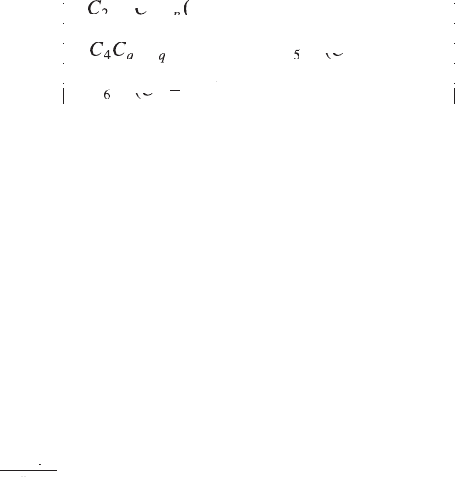
where N
design
is the design speed and C is a constant for unit conversion.
The coef cients C
2
, C
3
, C
4
, C
5
and C
6
are calculated using the boundary
conditions described above. Then the equivalent cam lift can be obtained
by considering both the dynamic and static de ections of the valvetrain
according to the following:
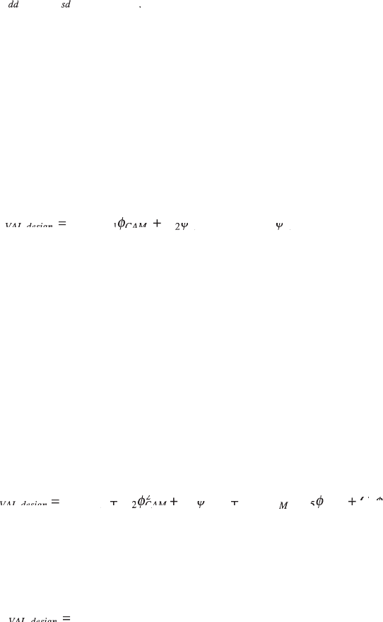
l
CAM,eq
= f
dd
a
VAL,design
+ f
sd
l
VAL,design
9.10
At any other speed than the design speed, the valve lift is solved by equation
9.6.
The actual cam lift is calculated from the equivalent cam lift as
follows:
l
l
l
CA
M
CA
Me
q
RA
CA
M,
ra
mp
=
+
,
Me,Me
f
RA
f
RA
f
9.11
where f
RA
is the rocker arm ratio, and l
CAM,ramp
is the ramp height at the cam
side as a function of cam angle. The nominal rocker arm ratio is de ned as
the maximum valve lift divided by the maximum cam lift. Strictly speaking,
the rocker ratio is actually a variable as a function of cam angle or valve lift.
Its value varies slightly from the position of valve closed to the position of
valve fully open, and reaches the maximum at the cam nose. The cam ramp
design is detailed in Section 9.4.4.
Equation 9.11 includes all the related factors that in uence the cam pro le
and the cam acceleration shape. Among them, the polynomial powers and the
design speed have the dominant effects. The polynomial powers affect the
height of the two positive pulses (humps) in the cam acceleration curve and
the shape of the acceleration curve (Fig. 9.18). The width of the positive cam
acceleration hump is strongly affected by the design speed, and increases as
the design speed increases. The valve lift pro le at other speeds is vibratory
due to different dynamic inertia effect. The vibration and the no-follow speed
are certainly affected by the polynomial powers and the design speed selected.
It is desirable to choose a design speed at the frequently encountered engine
speed since at the design speed by de nition the vibration amplitude is zero
theoretically. However, very often it is not possible to satisfy this condition
because of the need to achieve an acceptable no-follow speed. Usually, the
design speed has to be selected higher than the normal operating speed.
Diesel-Xin-09.indd 565 5/5/11 11:59:00 AM
566 Diesel engine system design
© Woodhead Publishing Limited, 2011
Longer duration of the main cam event results in lower vibration amplitude,
higher no-follow speed and lower contact stress between the cam and the
follower. The in uence of the maximum cam lift is opposite to the effect
of the main cam event: higher maximum cam lift results in higher vibration
amplitude and higher cam stress.
Cam acceleration pro le must be very smooth in order to achieve good
dynamic characteristics especially at high engine speeds. The derivative of
acceleration, cam jerk, also needs to be continuous and preferably smooth.
Any discontinuous and sharp acceleration and its consequent inertia load are
equivalent to a hammer blow to the valvetrain system and must be avoided.
The width of the positive acceleration hump should be greater than the time
of one cycle period corresponding to the valvetrain natural frequency in
order to avoid valvetrain separation within the range of operating speeds.
The initial compression of the valvetrain when the valve begins to open
causes the vavletrain to vibrate or rebound at its resonant frequency. Using a
wide acceleration hump ensures a compressive load acting on the valvetrain
throughout the period of the rebound. The aggressiveness of cam acceleration
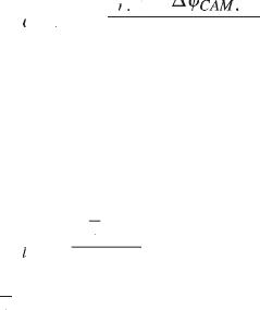
can be characterized by a coef cient of cam positive acceleration hump,
de ned as
f
f
ac
nV
f
nV
f
Ta
nVTanV
c
E
CA
f
CA
f
M
CA
TaCATa
TaMTa
N
,
M,M
,
nV,nV
·
Ta
·
Ta
D
Ta
D
Ta
f
Ta
f
Ta
,
Ta,Ta
9.12
where Df
CAM,ac
is the width of cam positive acceleration hump in crank
angle, f
n,VT
is the valvetrain natural frequency, and N
E
is the engine speed.
Note that higher f
CAM,ac
results in lower valvetrain vibration and less valve
ow area. The aggressiveness or roundness of the valve lift pro le can be
characterized by a coef cient of valve lift roundness as follows:
f
l
l
lift
f
lift
f
VAL
l
VAL
l
VAL
,m
ax
9.13
where
l
VAL
l
VAL
l
is the average valve lift over the valve event, and l
VAL,max
is
the maximum valve lift. A larger f
lift
gives larger valve ow area and less
pumping loss.
In order to achieve lower valvetrain vibration and higher no-follow
speed, the positive cam acceleration hump must be designed wider, lower,
and smooth. There are three ways to achieve this goal: (1) increasing
the valve event duration at a given maximum valve lift; (2) reducing the
aggressiveness of the valve lift pro le; or (3) reducing the maximum cam
lift by reducing the maximum valve lift or increasing the rocker arm ratio.
Unfortunately, all these measures have negative effects on either engine
breathing performance or cam stress. For instance, longer intake valve
duration and later IVC timing may reduce the volumetric ef ciency at low
Diesel-Xin-09.indd 566 5/5/11 11:59:01 AM
567Advanced diesel valvetrain system design
© Woodhead Publishing Limited, 2011
engine speeds; and using larger rocker arm ratio may cause an increase in
cam force and cam stress.
Cam radius of curvature is directly affected by cam base circle radius, roller
radius of the follower (in the case of roller followers), cam lift, cam velocity,
and cam acceleration. The minimum allowable cam radius of curvature should
be determined as a design target since it affects cam stress and the cost or
the feasibility of cam manufacturing. A too gentle cam acceleration prole
tends to produce a sharp nose in the cam lift prole with a very small radius
of curvature and hence increases the cam stress at the cam nose. On the other
hand, a more aggressive cam acceleration prole results in excessively small
or even negative radius of curvature at the cam ank. The aggressiveness of
cam acceleration is often limited by the minimum allowable negative radius
of curvature (for roller followers). This is especially true for the overhead
cams where the valvetrain no-follow is usually not a limiting factor due to
very high stiffness of the OHC valvetrain.
The elastic contact stress (i.e., the Hertzian stress) between the cam and
the follower needs to be calculated by either a cylindrical contact (also called
line contact) model or a more accurate elliptical contact model. The maximum
allowable stress limits are different for different materials (Kitamura et al.,
1997), types of followers (at-faced tappet, spherical follower, roller follower;
Turkish, 1946), surface crown designs (at-faced without a crown, or crowned
surface with a nite radius to avoid edge loading), surface nishes, and
lubrication conditions (Wang, 2007). Cam ash temperature also needs to
be calculated in cam design for the sliding motion with at-faced followers
because cam scufng and wear failures are associated with the temperature in
the contact zone. Usually, the highest ash temperature occurs at the highest
combination of cam force and engine speed (sliding speed). Moreover, a
good cam design needs to have satisfactory lubrication characteristics (e.g.,
oil lm thickness). More detailed discussions on cam stress and wear are
covered in Chapter 2 related to engine durability. Valvetrain lubrication,
friction, and ash temperature are discussed in Chapter 10. More in-depth
investigations on the cam ash temperature calculations are provided by
Dyson and Naylor (1960), Yang et al. (1996), and Ito et al. (2001).
Detailed information on the mathematical formulations of dynamic cam
design are presented by Thoren et al. (1952), Stoddart (1953), and Jensen
(1987). A cam design approach, ‘n-harmonic cam’, was proposed by Hanaoka
and Fukumura (1973) as a revision to the Polydyne cam design method.
More discussions on cam design guidelines or techniques are provided by
Roggenbuck (1953), Nourse et al. (1961), and Kanesaka et al. (1977).
9.4.4 Kinematic cam design
The kinematic cam design method has a vital importance for the following
three reasons. First, it connects the main cam event with the cam ramps via
Diesel-Xin-09.indd 567 5/5/11 11:59:01 AM

568 Diesel engine system design
© Woodhead Publishing Limited, 2011
kinematic constraints. Secondly, it can produce the cam lift pro le by directly
integrating a prescribed cam acceleration pro le when the dynamic cam
design method fails or cannot modify the cam acceleration pro le exibly or
locally. For example, when a special cam acceleration or lift pro le or some
local adjustment is needed, the single-piece polynomial used in the dynamic
cam design method may be too restrictive to make the change. Thirdly, the
kinematic cam design method is usually required for the end-pivot nger
follower OHC valvetrain because there is no dynamic cam design method
available to handle the two-dimensional motion of the follower. In this
section, the cam ramp design is introduced rst, followed by a description
of the cam pro le design within the valve event duration.
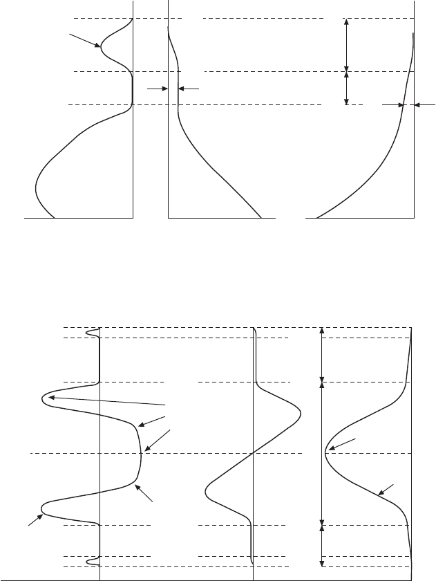
As shown in Figs 9.19 and 9.20, a cam pro le consists of three sections: an
opening ramp, a main cam event, and a closing ramp. The ramps must provide
a smooth transition between the cam base circle and the main event. The
function of the ramp is to take up the running clearances (e.g., the valvetrain
lash and the elastic compression caused by the valve spring preload) before
the valve opens or after the valve closes. Excessively long ramps should be
avoided for the exhaust cam because long and slow opening of the valve on
the ramp can cause excessive heating of the exhaust valve as the high-velocity
exhaust gas passes through the small opening. Long intake cam ramp may
lead to dif culties in cold start. Theoretically, the valve is supposed to open
and close precisely at the top of the ramp at a prescribed controlled kinematic
velocity. A constant-velocity ramp is most widely used at the opening and
closing sides (Fig. 9.19), especially with mechanical lash adjusters, in order
to control the opening and closing velocities. Accelerated opening ramps
(i.e., variable-acceleration, constant-acceleration or constant-jerk opening
ramps) are sometimes used with hydraulic lash adjusters to achieve faster
lift-off and a shorter ramp because there is no concern about the cold lash
and its associated mechanical impact (Fig. 9.20). The accelerated ramps
may also reduce valvetrain vibrations because the positive peak of the cam
acceleration may be reduced and a part of the dynamic inertia loading can
be transmitted to and shared by the opening ramp before the valve opens.
The reduced positive cam acceleration peak may enable a lower negative
cam acceleration so that a softer spring may be used to reduce the valvetrain
friction and the cam stress (Fig. 9.16).
The mathematical formulation of connecting the constant-velocity opening
ramp (Fig. 9.20) with the main cam event is given as follows:
va
l
CA
va
CA
va
MO
va
MO
va
penRam
va
penRam
va
MOpenRamMO
va
MO
va
penRam
va
MO
va
pC
va
pC
va
penRampCpenRam
va
penRam
va
pC
va
penRam
va
AM
pCAMpC
Op
enRamp
CA
M
C
CA
M
,,
pC,,pC
AM,,AM
pCAMpC,,pCAMpC
,,
MO,,MO
penRam,,penRam
MOpenRamMO,,MOpenRamMO
pC,,pC
penRampCpenRam,,penRampCpenRam
va =va
va
pC
va =va
pC
va
d
va dva
pC
d
pC
va
pC
va dva
pC
va
AM
d
AM
pCAMpC
d
pCAMpC
Op
d
Op
enRamp
d
enRamp
CA
d
CA
M
d
M
d
va dva
va
pC
va dva
pC
va
,1–2
d
,1–2
d
pC
0
pC
0
pC
0
pC
pC,,pC
0
pC,,pC
D
Ú
pC
Ú
pC
va
pC
va
Ú
va
pC
va
Ú
pC
Ú
pC
pC,,pC
Ú
pC,,pC
d
Ú
d
va dva
Ú
va dva
va
pC
va dva
pC
va
Ú
va
pC
va dva
pC
va
pC
0
pC
Ú
pC
0
pC
0
Ú
0
pC
0
pC
Ú
pC
0
pC
pC,,pC
0
pC,,pC
Ú
pC,,pC
0
pC,,pC
f
CA
f
CA
d
f
d
f
AM
AAMA
CACAMCAC
Op
enRamp
,,
Op,,Op
enRamp,,enRamp
=
d
00
D
ÚÚ
,,
ÚÚ
,,
d
ÚÚ
d
d
,1–2
d
ÚÚ
d
,1–2
d
00
ÚÚ
00
,,
00
,,
ÚÚ
,,
00
,,
D
ÚÚ
D
ff
ÚÚ
ff
ÚÚ
CA
ÚÚ
CA
ff
CA
ÚÚ
CA
MC
ÚÚ
MC
ff
MC
ÚÚ
MC
d
ÚÚ
d
ff
d
ÚÚ
d
MC
d
MC
ÚÚ
MC
d
MC
ff
MC
d
MC
ÚÚ
MC
d
MC
d
ÚÚ
d
ff
d
ÚÚ
d
CA
d
CA
ÚÚ
CA
d
CA
ff
CA
d
CA
ÚÚ
CA
d
CA
MC
d
MC
ÚÚ
MC
d
MC
ff
MC
d
MC
ÚÚ
MC
d
MC
,1–2
ÚÚ
,1–2
ff
,1–2
ÚÚ
,1–2
MC,1–2MC
ÚÚ
MC,1–2MC
ff
MC,1–2MC
ÚÚ
MC,1–2MC
d
,1–2
d
ÚÚ
d
,1–2
d
ff
d
,1–2
d
ÚÚ
d
,1–2
d
MC
d
MC,1–2MC
d
MC
ÚÚ
MC
d
MC,1–2MC
d
MC
ff
MC
d
MC,1–2MC
d
MC
ÚÚ
MC
d
MC,1–2MC
d
MC
MC
AM
MCAMMC
CA
MO
pe
MOpeMO
nR
am
pC
ampCam
AM
pCAMpC
v
()
CA
()
CA
MO
()
MO
penRam
()
penRam
MOpenRamMO
()
MOpenRamMO
p
()
p
penRamppenRam
()
penRamppenRam
MC
()
MC
AM
()
AM
MCAMMC
()
MCAMMC
a
()
a
,,
()
,,
CA,,CA
()
CA,,CA
MO,,MO
()
MO,,MO
d
()
d
CA
d
CA
()
CA
d
CA
MO
d
MO
()
MO
d
MO
penRam
d
penRam
()
penRam
d
penRam
MOpenRamMO
d
MOpenRamMO
()
MOpenRamMO
d
MOpenRamMO
p
d
p
()
p
d
p
penRamppenRam
d
penRamppenRam
()
penRamppenRam
d
penRamppenRam
MC
d
MC
()
MC
d
MC
AM
d
AM
()
AM
d
AM
MCAMMC
d
MCAMMC
()
MCAMMC
d
MCAMMC
a da
()
a da
00
()
00
,,
00
,,
()
,,
00
,,
ÚÚ
()
ÚÚ
d
ÚÚ
d
()
d
ÚÚ
d
00
ÚÚ
00
()
00
ÚÚ
00
,,
00
,,
ÚÚ
,,
00
,,
()
,,
00
,,
ÚÚ
,,
00
,,
ff
()
ff
MC
ff
MC
()
MC
ff
MC
d
ff
d
()
d
ff
d
MC
d
MC
ff
MC
d
MC
()
MC
d
MC
ff
MC
d
MC
ÚÚ
ff
ÚÚ
()
ÚÚ
ff
ÚÚ
MC
ÚÚ
MC
ff
MC
ÚÚ
MC
()
MC
ÚÚ
MC
ff
MC
ÚÚ
MC
d
ÚÚ
d
ff
d
ÚÚ
d
()
d
ÚÚ
d
ff
d
ÚÚ
d
MC
d
MC
ÚÚ
MC
d
MC
ff
MC
d
MC
ÚÚ
MC
d
MC
()
MC
d
MC
ÚÚ
MC
d
MC
ff
MC
d
MC
ÚÚ
MC
d
MC
f
()
f
CA
()
CA
CCAC
()
CCAC
MC
()
MC
D
pC
D
pC
Ï
Ì
Ô
Ï
Ô
Ï
Ô
Ô
Ô
Ô
Ô
Ì
Ô
Ì
Ô
Ô
Ô
Ó
Ô
Ì
Ô
Ì
Ô
Ô
Ô
Ô
Ô
Ó
Ô
Ó
Ô
Ô
Ô
d
MC
d
MC
+
,,
MO,,MO
pe,,pe
MOpeMO,,MOpeMO
nR,,nR
am,,am
pC,,pC
ampCam,,ampCam
AM,,AM
pCAMpC,,pCAMpC
2–3
f
MC
f
MC
f
pC
f
pC
pC,,pC
f
pC,,pC
9.14
Diesel-Xin-09.indd 568 5/5/11 11:59:02 AM
© Woodhead Publishing Limited, 2011
The slope, height and
width of the pulse affect
valvetrain vibration
Cam ramp design with
mechanical lash adjuster
Cam ramp design with
hydraulic lash adjuster
The slope affects
no-follow, cam
curvature and stress
Affects cam radius
of curvature
Opening
ramp
Closing
ramp
Main cam event
Cam nose
Cam flank
f
CAM
Df
CAM, 6-5
Df
CAM, 7-6
1 2 3 4 5 6 7
Cam acceleration
Cam acceleration
Cam velocity
Cam velocity
Cam lift
Cam lift
5 6 7
a
CAM,CloseRamp
v
CAM,CloseRamp
I
CAM,CloseRamp
9.19 Cam ramp
blending in cam
design.
Diesel-Xin-09.indd 569 5/5/11 11:59:02 AM
