Werner Leonhard Control of Electrical Drives
Подождите немного. Документ загружается.

2./'
- ó
~
I
:HO
11. Power Supplies for
Adjustable
Speed
AC Drives
L
I
Ul2
c
2
8
/1pply
o
U23
3
-o
I
3.,,101
2 t 3
Load
D Principie
of
a cross
bar
connection
b Example
of
switching arrangement
TC
UI
u2
U3
U,2
(1)
'6
~[
tI
w,t
=f
c Selection
of
fine
voltages
d Bidirectional switches
I;'i~.
11.20.
Principie
of
a
PWM
matrix
converter for
generating
viLri
"
tb
le
frequency voltages
directly
from
the
line volt ages
lU . '
a
voi(
I(
~
d
,
thus
facilitating large scale
integration
with semiconductors.
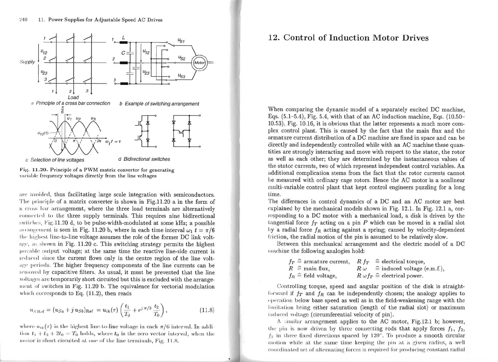
TIl!' prillciple of a
matrix
converter is shown
in
Fig.11.20 a in
the
form
of
II
.
crel
;;S
h
;1.1'
al'rangement, where
the
three
load
terminals
are
alternatively
(·
"I!II!'cl.I
'
t1
1.0
the
three
supply terminals.
This
requires nine bidirectional
Ii
w
Íl
.dl\
·:
;,
t"Íf.(
.11.20 d,
to
be
pulse-width-modulated
at
some kHzj a possible
;
••
' :
\lII
',1'
III('Il[.
is seen in Fig. 11.20 b, where
in
each
time
interval
Wl
t = 1r/6
iiI<'
Il
il';
lwsl.
tine-to-line voltage assumes
the
role
of
the
former
DC
link volt-
ai
'
.•
',
;I.
~:
shown in Fig. 11.20
c.
This switching
strategy
permit
s
the
highest
pO
: ; : :
lhl(
~
output
voltagej
at
the
sarne
time
the
reactive line-side
current
is
n'd
u('(
~
d
sillce
the
current
flows only in
the
centre
region of
the
line volt-
'
q'
." p
('
rioc!
s.
The
higher frequency components of
the
line
currents
can
be
l('lll()v(~d
hy capacitive filters. As usual,
it
must
be
prevented
that
the
line
v()ll.;q
;
l
~s
are
temporarily
short
circuited
but
this
is excluded
with
the
arrange-
1II
I:
lll.
of
sw
itcbes in Fig. 11.20 b.
The
equivalence for vectorial
modulation
\V
Iii.:" w rrcsponds
to
Eq
. (11.2),
then
reads
'
/t
s I
!.,
.r =
(USa
+ j
USb)Rer
=U ik (r)
(
~~)
_ e
j
,,/3
12
)
(11.8)
1'0
'
wll(
~
l'!
~
'II
id'1')
is
t.lw
hil
~
ll
cst
1i\H
~
"
I,()
·
lin
('
voll.lIl
~
'·
iII
('jL('h
'
Ir
j (j
..
illt
nva
.l.
ln a
dcli
·
tillll
1' 1 I I .
....
I 2/'0 'III Ilolds,
wlwn
~
1'0 i
i-!
1.110'
'1.
('1'0
vI'cl,or i
lll.<
;rval , wbclI
I.hc
11I1I!.
!,r
i:
:
....
h"rI
. dl'('uil.l·
d,
a.
1.
0111'
01'
1.
11('
lill!' 1.(·I·
II
IÍ
llill
rI,
f i/\,
II)!.
12.
Control
of
Induction
Motor
Drives
When
comparing
the
dynamic
model
of a
separately
excited DC machine,
Eqs.
(5
.
1-5.4),
Fig
. 5.4,
with
that
of
an
AC
induction
machine, Eqs, (10.50-
10.53), Fig. 10.16,
it
is
obvious
that
the
latter
represents a much
more
com-
plex cOntrol planto
This
is caused by
the
fact
that
the
main
flux
and
th
e
armature
current
distribution
of a DC machine
are
fixed in space
and
can
be
directly
and
independently
controlled while
with
an
AC machine these
quan-
tities
are
strongly
interacting
and
move with respect
to
the
stator,
the
rotor
as well as each otherj
they
are
determined
by
the
instantaneous
values
of
t,he
stator
currents,
two
of
which represent
independent
control variables. An
a
dditional
complication
stems
from
the
fact
th
at
the
rotor
currents
cannot
ue
measured
with
ordinary
cage rotors. Hence
the
AC
motor
is a nonlinear
multi-variable control
plant
that
kept
cOntrol engineers puzzling for a long
time.
The
differences in control
dynamics
of
a
DC
and
an
AC
motor
are
best
<~xplained
by
the
mechanical mo deIs shown in Fig.
12
.
1.
ln
Fig
.
12
.1 a, cor-
I'
cs
ponding
to
a DC
motor
with
a mechanical load, a disk is driven by
th
e
I.angential force
Ir
acting
on
a
pin
P which can
be
moved in a
radial
slot
I,y
a
radial
force
IR
acting
against
a springj caused by velocity-dependent
I'ri
ctio
n,
the
radial
motion
of
the
pin
is assumed
to
be
relatively slow.
Between this mechanical
arrangement
and
the
electric model
of
a DC
II
I<l<:hine
the
following analogies
hold
:
IT
~
armature
current,
R h
~
electrical torque,
R
~
main
fiux,
R W
~
induced voltage (e.m.f.),
IR
~
field voltage, RW
IT
~
electrical power.
Controlling torque, speed
and
angular
position
of
the
disk is
straight-
IllI'w
ard
if
h
and
IR
can
be
independ
ently chosenj
the
analogy applies
to
"pI'I'atioll below base speed as well as in
the
fi
eld-weakening range
with
th
e
lill,il.a
l.i
o
ll
bcing e
ither
saturation
(length of
the
radial
slot) or
maximum
·'I
,dll
('.(
~
d
vo
Jt
age (circumferential velo city of pin).
1\
::
illlil
ar
arra
nge
ment
applics
to
the
AC
motor,
Fig.12.1 bj however,
1.
1J
l'
pi
ll
i~
;
1I
0W
drivc
ll
by
three
CO
llllecting rods
that
apply
forces h ,
h,
,I
III
l.
il
l'I'I'
li
x(·d
din'
l'.l
iollS Rp
a.<:ed
hy
'1
20
°. To procluce a
smooth
circular
III,tI
.
io
ll
w
il
i
l,'
11.1.
I.
II!'
/la
lIlC'
t.il1w
1
<l.:
I,.,illl', (,
II!'
pill
;d,
a
p;ivI'1I
radius, a
v
J!'~
1l
I ,
,,
»
,I
I
II
n I.," I i Id . "r I
tll.,
'1·IH
tI
.i II
I'
,
rc
,rC
'1
'II
ln I
"1(
II
iI"d r, I I' I"
'.
,d
II.'
iI 'I';
l'Oll
N
l.
a
lJ
t.
r;
l(
I ial
- 2008 — 2025 «СтудМед»