Werner Leonhard Control of Electrical Drives
Подождите немного. Документ загружается.

200
10.
Symmetrical
Three-Phase
AC Machines
xs{t}
I
I
I
I
~
H
~.
I
II
t'
11111i
• I
IIIIIIIIII'~(\.~----------t-------
'Idlll"
~
I
II I o , I
!~~'Ys(t)
I
I
I
I
1
51
I
I
.!!L(t)
m
L
="2
m
po
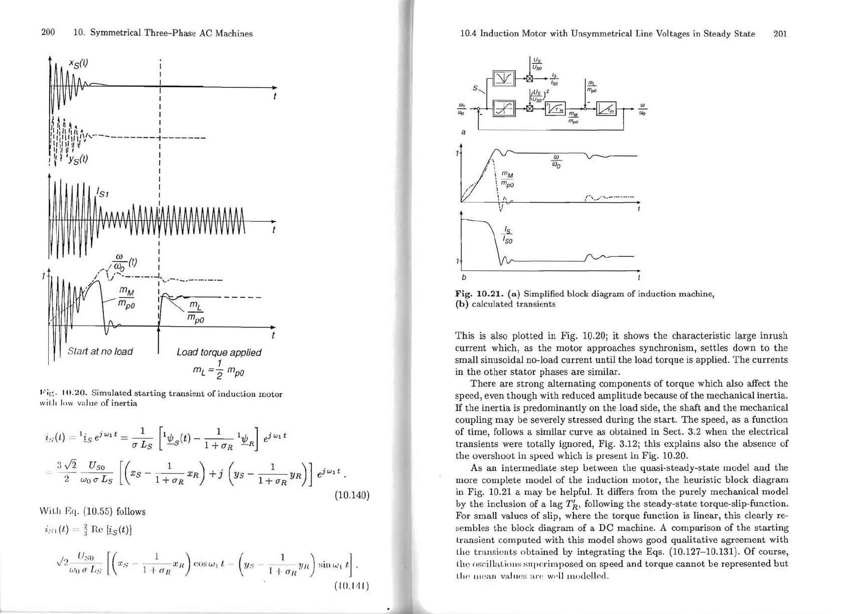
Fi,
,,
.
10.20.
S
imulated
starting
transient
of
induction
motOr
wil.lt I<l W value of
inertia
iv
(t,)
=
li
e
j
wd
=
_1_
[1'IjJ
(t)
__
1_
1'IjJ
]
ejw1t
, . -s
(7
L s
-s
1 +
(7
R
-R
:
~
12
Uso
~
.-
-
--
xs
-
_1
XR)
+j
(YS
1
YR)]
.
__
ejw1
t
2
Wo
(7
Ls
[(
1 +
(7R
1 +
(7R
(10.140)
Wil,h
r
~
q.
(10.55) follows
'i:
>i
(l) = 1Re [is(t)]
(/
~
'II
f(
1 )
J
:~
'
:/
:,'; -
---
Xli
CO
:-)
W
I/'
1
lI
n
) S
ill
Ü)
lt
'l,
(A
i l )
ri
/,
::
1 I {r
ll
eI
S
(T
li
c
(10, 111)
I
r
./
úJo
.-.-1.
,_,_._,_
/
'./
.....
-.-
1'-
n
mM
I
'
~.-
I
/'-
-----
m
po
I
m
L
I
m
po
Sta
/1
at
no load
Load forque applíed
1
10.4
Indu
c
tion
Motor
with
Unsymmetrical
Line Voltages
in
Steady
State
201
w
~
"'o
"'o
a
W
"I
I;
\
W
o
" \
mM
/ ! 1m
/)
\
po
~
(.
r·
\ .
./
·
....
·-------
,/
"
b
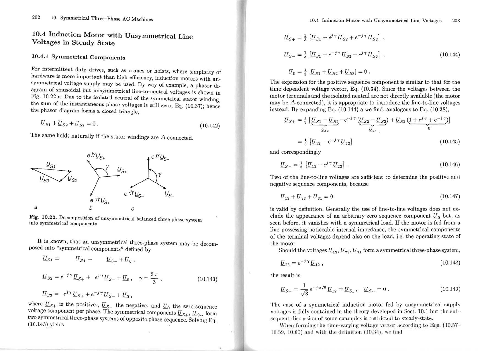
Fig.
10.21.
(a)
Simplified block
diagram
of
induction
machine,
(b)
calculated
transients
This
is
also
plotted
in Fig. 10.20;
it
shows
the
c
haracteristic
large
inrush
current
which, as
the
motor
approaches synchronism, settles down
to
the
small sinusoidal no-load
current
until
the
load
torque
is applied,
The
currents
in
the
other
stator
phases are similar.
There
are
strong
alternating
components of
torque
which also affect
the
speed, even
though
with reduced
amplitude
because of
the
mechanical
inertia
.
If
the
inertia
is predominantly
on
the
load side,
the
shaft
and
the
mechanical
coupling
may
be severely stressed during
the
start.
The
speed, as a function
of time, follows a similar curve as
obtained
in
Sect. 3,2 when the electrical
transients
were
totally
ignored, Fig. 3.12; this explains also
the
absence of
the
overshoot in speed which is
pr
esent in Fig. 10.20,
As
an
intermediate
step
between
the
quasi-steady-state model
and
the
more complete model of the induction motor,
the
heuristic block
diagram
in Fig. 10.21 a may
be
helpful.
It
differs from
the
purely mechanical model
by
the
inclusion of a lag
T~,
following
the
steady-state
torque-slip-function.
For small values of slip, where
the
torque function
is
linear, this clearly re-
sembles
the
block diagram of a
De
machine. A comparison of
the
starting
transient
computed
with
this
model shows good qualitative agreement with
Lhe
transi
ellts o
bt
ained by integrating
the
Eqs. (10.127-10.131).
Of
course,
Lh
e os(:illa(,
iom;
Hl1p
erimposed on speed
and
torque
cannot
be
represented
but
I.I)(
~
lJl(
:
all
viI,
I'W
H
!
~
i'(
:
wdl
luo<!elkc!.
202
10.
Symmetrical
Three-Phase
AC Machines
10.4
Induction
Motor
with
Unsymmetrical
Line
Voltages
in
Steady
State
10.4.1
Symmetrical
Components
For
intermittent
duty
drives, such as cranes
or
hoists, where simplicity
of
hardware
is more
important
than
high efficiency, induction motors with un-
symmetrical
voltage supply
may
be used. By way
of
example, a phasor di-
agram
of
sinusoidal
but
unsymmetricaJ line-to-neutral volt ages is shown
in
Fig. 10.22
a.
Due to
the
isolated neutral
of
the
symmetrical
stator
winding,
the
sum
of
the
instantaneous phase voltages is still zero, Eq. (10.37); hence
the
phasor
diagram forms a elosed triangle,
fl
51
+ U
52
+ U
53
= O .
(10.142)
The
sarne holds
naturally
if
the
stator
windings are Ll-connected.
ejY!)s+
!)S1
~s+À
~S2
e -fYl}s-
!)S-
e -jy l}s+
a
b
c
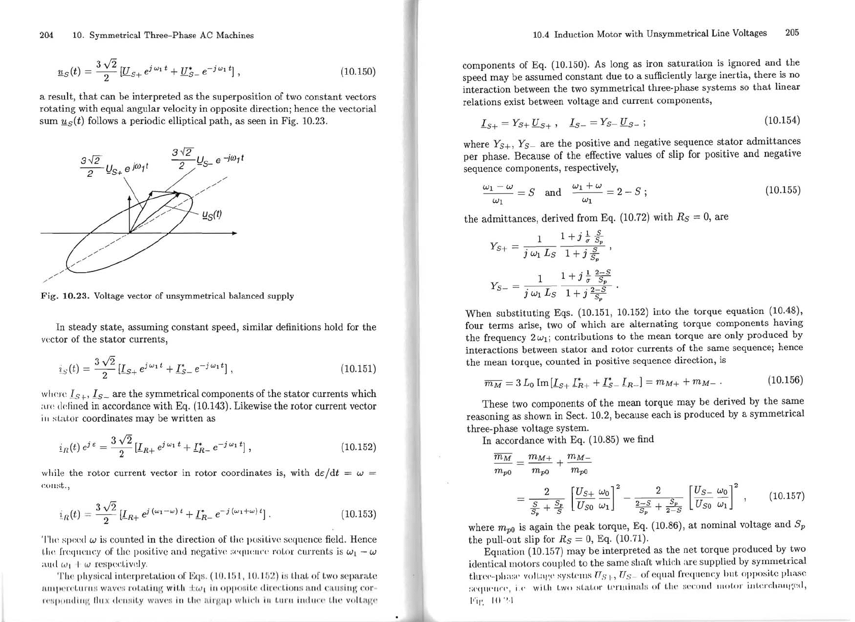
Fig.
10.22.
Decomposition
of
unsymmetrical
balanced
three-phase
system
into
symmetrical
components
It
is known,
that
an
unsymmetrical three-phase system
may
be
de com-
posed into "symmetrical components" defined by
U
51
=
u
5
++
U
5-
+
fl.o
,
U
52
=
e-h
U5 + +
eh
U5 _ +
fl.o
,
211"
(10.143)
1=3'
U
53
=
ehfl5++e-hU5_+fl.o,
where U
5+
is
the
positive-, U
5-
the
negative-
and
fl.o
the
zero-sequence
volt age component
per
phase.
The
symmetrical components fl5+' U 5
.-
form
two symmetrical three-phase systems
oE
oppositc phase-sequencc. Solvilll( Eq.
(10.14.1) yi(dds
10.4
Induction
Motor
with
Unsymmetrical
Line Voltages
203
U
-
-
1
[U
-51
+ h
-52
U +
-h
U ]
,
-5
+
3"
e
e_53
U
-
-
3"
1
[u
+
e
-h
U +
e_53
h U ]
(10.144)
-5
-
-51 -52
,
fl.o
= 1
[U
51
+ U
52
+ u
53]
= O .
The
expression for
the
positive sequence component is similar
to
that
for
the
time
dependent volt age vector, Eq. (10.34). Since
the
volt ages between
the
motor
terminals
and
the
isolated
neutral
are
not
directly available
(the
motor
may
be
Ll-connected),
it
is
appropriate
to
introduce
the
line-to-line voltages
instead. By expanding Eq.
(10.144) a we find, analogous
to
Eq. (10,38),
U
5+
= 1[U
51
- U
52
-e-h
(fl52 - u
53)
+ u
52(1
+ e
h
+
e-h)]
v
!L
12
!L
23
'--v---'
'--v---'
=0
-
3"
1
[U
-
-hu]
-23
-
-12
e
(10.145)
and
correspondingly
fl5-
= t
[U
12
-
eh
U
23
]
(10.14G)
Two
of
the
line-to-line volt ages are sufficient
to
determine
the
positive ,Uld
negative sequence components, because
U12 + U
23
+ U
31
= O
(10.147)
is valid by definition. General1y
the
use
of
line-to-line volt ages does
not
ex-
elude
the
appearance
of
an
arbitrary
zero sequence component
fl.o
but,
as
seen before,
it
vanishes
with
a symmetrical load.
If
the
motor
is fed from a
line possessing noticeable internal impedance,
the
symmetrical components
of
the
terminal
volt ages depend also
on
the
load, i.e.
the
operating
state
of
the
motor.
Should
the
voltages U
12'
U
23'
~1
form a
symmetrical
three-phase system,
u =
e-j,,!
U
,
(10.148)
23
12
the
result is
e-
j7r
/
6
U- 1
-U
U-O
(10.H!))
-5+
U
-
J3
-12
-
-51'
-5
- - .
'l'hc case
of
a symmetricaJ induction
motor
fed by unsymmetrical snpply
vol
(.agci-i
is
fully containecl in the thcory developed in Scct. 10.1 bllt til<:
sllb
-·
~Cq'I('Ilt
dis(".I\~;:;i()Jl
oE
som(~
cX<tmpks
is
J'(~st.rid<:(l
t.o
steady-state.
WIlI'll l'''r1Ui
11/';
t.he
t.i"w-varyiHI
~
vol!.al(
(·
V(·('t.()f
H!'
.
(
~
()nlillf~
t.o
J
~;
qs.
(10
.;)'(
IO
.:,n,
IO
.
(iO)
lUtei
wit.it 1.
11('
ddillit.io!l (10.:\
.-
1),
WI'
lillel
204
10.
Symmetrical
Three-Phase
AC Machines
u (t) = 3
v2
[U
ei
Wl
t +
U'
e-i
Wl
tj
(10.150)
-s
2
-s+
-5-
,
a result,
that
can be
interpreted
as
the
superposition of two
constant
vectors
rotating
with equal
angular
velocity in opposite directioni hence
the
vectorial
sum
1!cs
(t) follows a periodic elliptical
path,
as seen
in
Fig. 10.23.
3{2
-j
w
1
t
-
Us_e
3..J2 U e
jW1
t
2 -
2- -s+
ldS(t)
///
/"
"-
----
Fig.
10.23.
Volt age vector of
unsymmetrical
balanced
supply
ln
steady
state,
assuming
constant
speed, similar definitions hold for
the
vector of
the
stator
currents,
i.(t)=3
v2
[I
eiw1t+I*
e-
iw1t
j
(10.151)
-s
2 -s+
-s-
,
w"cre
Is
t,
Is-
are
the
symmetrical components of
the
stator
currents which
;1.1"<:
ddined
in accordance
with
Eq. (10.143). Likewise
the
rotor
current vector
iII
sLal.or coordinates
may
be
written
as
í
(t)e
jo
=
3v2[I
eiw1t+I*
e-
jw1t
j
(10.152)
-lI
2
-R+
-R-
,
while
the
rotor
current vector in rotor coordinates is, with de:/dt = W
COllst.
,
,.
(t)
- 3
v2
[I
j
(WI-
W
) t +
1*
e-j
(wd-
w
)
tj
(10.153)
Ln
- 2
-R+
e
-R-
.
'I'hc spced w
i::;
counted in
the
direction of
th<:
positive sequClIce field. Rence
1.1)(',
frcqllcllcy 01' tlte positive and negativ(' ;'
('<I\lCI[('('
roLor
c
urrents
is W.l - W
;1.l1d C"'I 1 w
rl'~qJC(",(.jv(~I'y.
'1'111"
ph'y
~
:jnd
ill!.(:rprd,aÜol\
of
1':1)
11
.
(I
O.I~;
I,
1
(!.
IIJ
:.t
) iM
LIIILL
or
(.wo
li
cparal.c
II
11L1'
..
rl'i.ll
rll
li WII.V , ')i
"(J
I./tl.i
111
':
wi!."
I l
<i
l
iII
"PI,
olIl
!.(·
dlrC'd.i(H
Hl
ll
llld
l
( 'l
lIlH
illJ
~
cor
I'c'I
'(II
,
'lId
l
lll
\
1111
K
d('II:
d
!.y
WIL
VI'
1i
iII
1.1.
0
lI.lr
r'.II,p w
\"dl
i"
1.111
'
11
IlIclll""
i'.I
'l('
v"IL
l
lj
~('
10.4
Induction
Motor
with
Unsymmetrical
Line Voltages
205
components of Eq. (10.150).
As
long as iron
saturation
is
ignored
and
the
speed
may
be assumed
constant
due
to
a sufficiently large inertia,
there
is
no
interaction
between
the
two symmetrical three-phase systems so
that
linear
relations exist between volt age
and
current
components,
(10.154)
Is+ = ys+ U
s+,
Is-
=
Ys-
U
5-
i
where
Ys+,
Ys-
are
the
positive
and
negative sequence
stator
admittances
per
phase. Because of
the
effective values
of
slip for positive
and
negative
sequence components, respectively,
Wl
- w = S
and
Wl
+W
= 2 _ S i
(10.155)
Wl
Wl
the
admittances,
derived from Eq. (10.72) with
Rs
=
O,
are
1
l+jl~
17
sp
Y
s+
= . . s
J
Wl
Ls
1 +
Js
p
1 + . 1
2-S
Y = 1
JuS;:
S-
j
Wl
Ls
1 + j 2
S
S
p
When
substituting
Eqs. (10.151, 10.152) into
the
torque
equation (10.48),
four
terms
arise, two of which are
alternating
torque
components having
the
frequency 2
Wl
i contributions
to
the
mean
torque
are only produced by
interactions between
stator
and
rotor currents
of
the
sarne sequencei hence
the
mean torque, counted in positive sequence direction,
is
(10.156)
mM
= 3
Lo
1m
[1
5
+
DH
+
Is-
IR-l =
mM+
+
mM-
.
These two components of
the
mean
torque
may
be derived by
the
sarne
reasoning as shown in Sect. 10.2, because each is produced by a symmetrical
three-phase voltage system.
ln
accordance
with
Eq. (10.85)
we
find
mM
mM+
mM-
-=--+--
mpú
mpo
mpü
2
~
+
sp
5
p
S
Us+
Wo
[
]
2
U50
Wl
2
2-S
+
~
5
p
2-S
[
Us-
wo] 2
Uso
Wl
,
(10.157)
where
mpo is again
the
peak
torque, Eq. (10.86),
at
nominal voltage
and
Sp
the
pull-out slip for
Rs
=
O,
Eq. (10.71).
Eqnation
(10.157)
may
be
interpreted
as
the
net
torque
produced by two
identical
mol.ors
coupled
to
the
same shaft
whidl
are supplied by syrnrnetrical
tltn'('-plt":;I'
voll.;!.J',"
sysl.('llls
"s
I,
U
S
(lf
(~Il'lid
fl't
~
ljlICm(
:
y
hllt
oppo:-;ite pltasc
:;('<lIII'II('C
' , j ,
C'
wil.iI
!.wo sl.nl.or
I.('flllill
l
tl
ll
clI"
til\' H
I'I"tllld
\1101.01"
illkrchnl1i~(:d,
\,
iI'.
I II '1\
206
10.
Symmetrical
Three-Phase
AC Machines
ls+
!
1s-
!
w
Us+!
L-+----J
I )
IUS-!
L-+----J
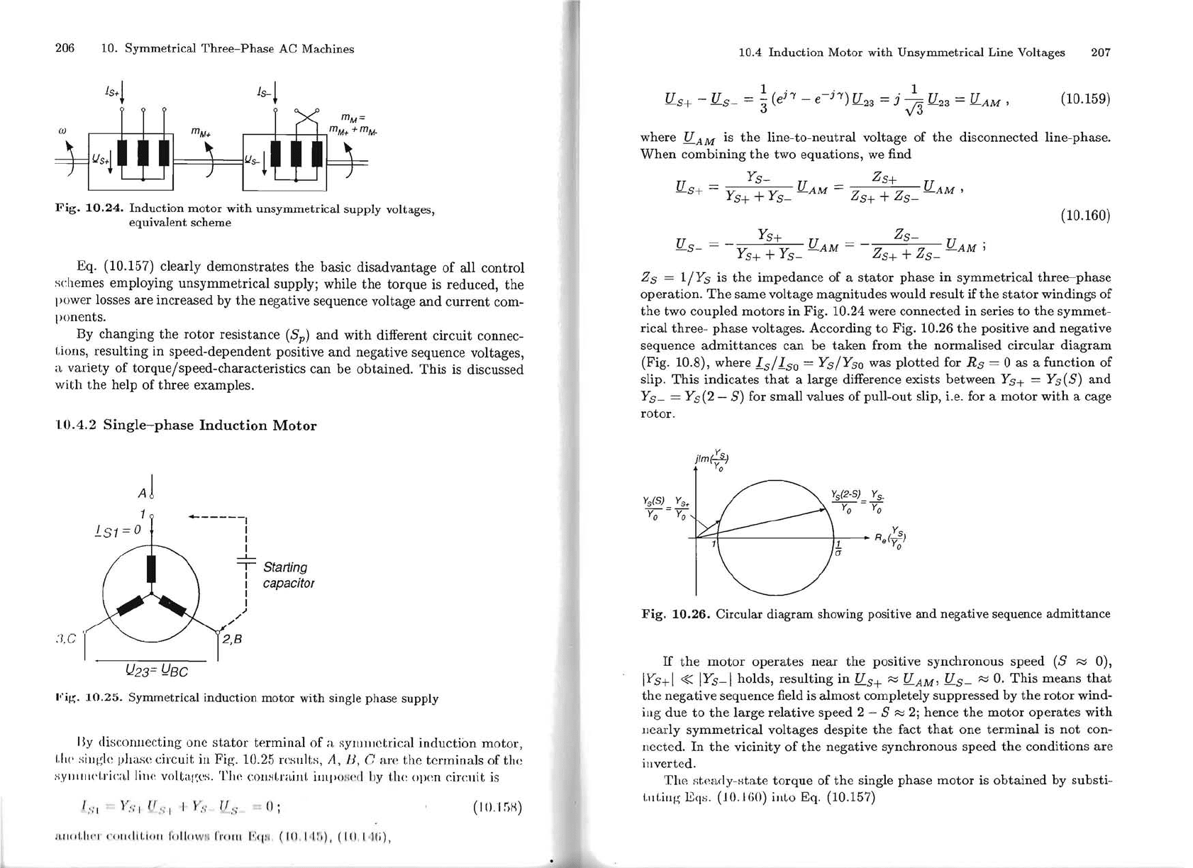
Fig.
10.24.
Induction
motor
with
unsymmetrical
supply
volt ages,
equivalent
scheme
Eq. (10.157) clearly demonstrates
the
basic disadvantage of alI control
schemes employing unsymmetrical supply; while
the
torque
is
reduced,
the
power losses are increased by
the
negative sequence voltage
and
current
com-
ponents.
By changing
the
rotor
resistance
(Sp)
and
with different circuit connec-
Lions,
resulting in speed-dependent positive
and
negative sequence voltages,
a variety
of
torque/speed-characteristics can be obtained.
This
is
discussed
with
the
help of three examples.
10.4.2
Single-phase
Induction
Motor
AI
------1
1
1
1
!..S1
=0
;'
;'
----L-
--,--
Starting
1
1
capacitor
1
1
~
:l.C
'I
Ih3=
I}BC
Fi!!:.
10.25.
Symmetrical
induction
motor
with
single
phase
supply
Ily discolluec:ting one
stator
terminal of a Rylllluctrical induction motor,
1,11(,
siuglc phase circ:uit
in
Fig. 10.25 rct;ul
ts,
A,
II,
n
an
'
t:he
terminaIs
of
the
H.Y1l111I('!.ric:\.!
lill(~
voltages.
The
cowll.,rnint,
iUlpO
!-l
cd
!Jy
t.h(~
opcn
circlIit
is
1
";
1
)
'
~
"l
l
r
:-:
II
V"
j
lJ,
,
;
=
H;
(10.1
;)H)
r
Ulld,II
"! <'(
111<1
1
1,
;
<111
\;
dl<1
1N
11
rrnfll
1·:'1
J1
. (
1.11
. 1<
[1
;), ( IU. l·ll'i),
10.4
Induction
Motor
with
Unsymmetrical
Line Volt ages 207
-
1 ( h
-h)
_.
1 _
U U
3 e - e U
23
- J
v'3
U
23
- U
AM
,
(10.159)
-s+
-
-s-
-
where
U
AM
is
the
line-to-neutral volt age of
the
disconnected line-phase.
When
combining
the
two equations,
we
find
U -
Ys-
U - Zs+ U
-s+
- y + y
-AM
- Z + Z
-AM,
s+
s-
s+
s-
(10.160)
Ys+
zs-
U
s
_
=
Ys+
+
Ys-
U
AM
=
Zs+ +
Zs-
U
AM
;
Zs
=
l/Ys
is
the
impedance of a
stator
phase in symmetrical
three-phase
operation.
The
sarne volt age magnitudes would result if
the
stator
windings of
the
two coupled motors in Fig. 10.24 were connected in series
to
the
symmet-
rical three- phase volt ages. According
to
Fig. 10.26
the
positive
and
negative
sequence
admittances
can be
taken
from
the
normalised circular
diagram
(Fig. 10.8), where
Is/Iso
=
Ys/Y
so
was
plotted
for
Rs
= Oas a function of
slip.
This
indicates
that
a large difference exists between Ys+ = Ys(S)
and
Ys-
= Ys(2 -
S)
for small values
ofpull-out
slip, i.e. for a
motor
with
a cage
rotor.
jlm(~)
Y
o
Ys(S)
Y
s
+
y;;-=y;
R Y
s
1.
.(-)
a Y
o
Fig.
10.26.
Circular
diagram
showing positive
and
negative
sequence
admittance
If
the
motor
operates
near
the
positive synchronous speed
(S
~
O),
IYs+1
«
IYs-1
holds, resulting in U s+
~
U
AM,
U
s-
~
O.
This
means
that
the
negative sequence field is almost completely suppressed by
the
rotor
wind-
ing due
to
the
large relative speed 2 - S
~
2;
hence
the
motor
operates
with
llearly
symmetrical
volt ages despite
the
fact
that
one
terminal
is
not
con-
nected.
ln
the
vicinity
of
the
negative synchronous speed
the
conditions
are
illverted.
Th('!
st.('ady-st.a.te
torque
of
the
single phase
motor
is
obtained
by substi-
LilLillg
Eqs.
(10.
HiO)
illlo Eq. (10.157)
208
10.
Symmetrical
Three-Phase
AC Machines
I
Ys.
I
Ys++Y
s
.
Sp
I
Ys+
I
Y
s
++
Y
s
.
2·
Sp
2 S
Fig.
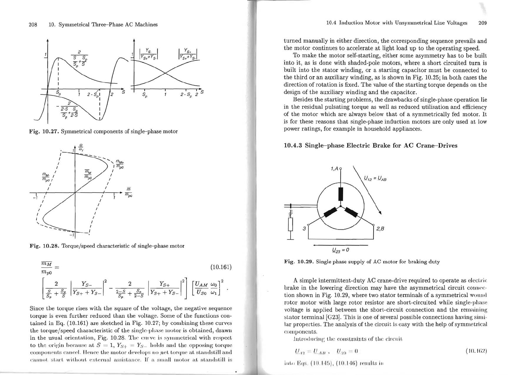
10.27.
Symmetrical
components
of
single-phase
motor
.Q!.
I
mM
I
11
úJ,
I
I
" m
M
+
, m
pO
I
I
mM· I
I
I
mpO
I
I
m
po
I
I _
m
----,---+
m
pO
'
.....
I
.....
-
I
-1
Fig.
10.28.
Torquejspeed
characteristic of single-phase
motor
mM
=
(10.161)
mpo
2
2
2
UAM
Wo
1
2
1
--s
YS-
[
~+s 1
YS+
YS+
+Y
s
-
2-S
+~
IYs+Y:+yJ]
[
Uso
wd
.
sp
s;-
2-S
Since
the
torque rises with
the
square
of
the
voltage,
the
negative sequence
torque
is
even
further
reduced
than
the
voltage. Some
of
the
f1.Jnctions
con-
tained
in Eq. (10.161)
are
sketched in Fig.
10
.
27;
by combining these curv
es
the
torque/speed
characteristic of
the
singlcvlt;1.se
motor
is obtained, drllwll
in
the
usual oricntation, Fig.
10
.28.
1'11('
ClIJ
V(~
is s'yl1llllctrica.l with
rm;ped
to
the
orif~ill
hc("all
s
(:
aI.
S =
1.,
ys, = yC; holdli a
lld
I,\l(~
o[l[los
iJl[!;
t.orqU(·
("()[lIpOIl(·IIf.
~ 1
(
'1
1.11<",
,1. 1I.'lIcl;
lhe
IlItlI.Ol" t!.
·V
••
I"
pH
IjO
.1
...
1,
I.ol"tliw
;ü
!;
I.
;lIId'!il.iU a
li.!
(
'11
1111<>1
i.I,
)
1I
I, wlt.lulllf,
('
xI,"l'lInl
ll
Nl
ii
tl
l,
IIIU
'O.
Ir
1\
/1
11 11
111
ItIllt.OI :d, 1;l.:l.Ild n
t.i\ll
1M
•
_.#'
10.4
Induction
Motor
with
Unsymmetrical
Line Voltages
209
turned
manually in
either
direction,
the
corresponding sequence prevails
and
the
motor
continues
to
accelerate
at
light load
up
to
the
operating
speed.
To make
the
motor
self-starting, either some
asymmetry
has
to
be
built
into it, as is done with shaded-pole motors, where a
short
circuited
turn
is
built into
the
stator
winding,
or
a
starting
capacitor
must
be
connected
to
the
third
or
an
auxiliary winding, as is shown
in
Fig. 10.25; in
both
cases
the
direction
of
rotation
is fixed.
The
value
of
the
starting
torque depends
on
the
design
of
the
auxiliary winding
and
the
capacitor.
Besides
the
starting
problems,
the
drawbacks
of
single-phase
operation
lie
in
the
residual
pulsating
torque
as well as reduced utilisation
and
efficiency
of
the
motor
which
are
always below
that
of
a symmetrically fed motor.
It
is for these reasons
that
single-phase induction motors
are
only used
at
low
power ratings, for example in household appliances.
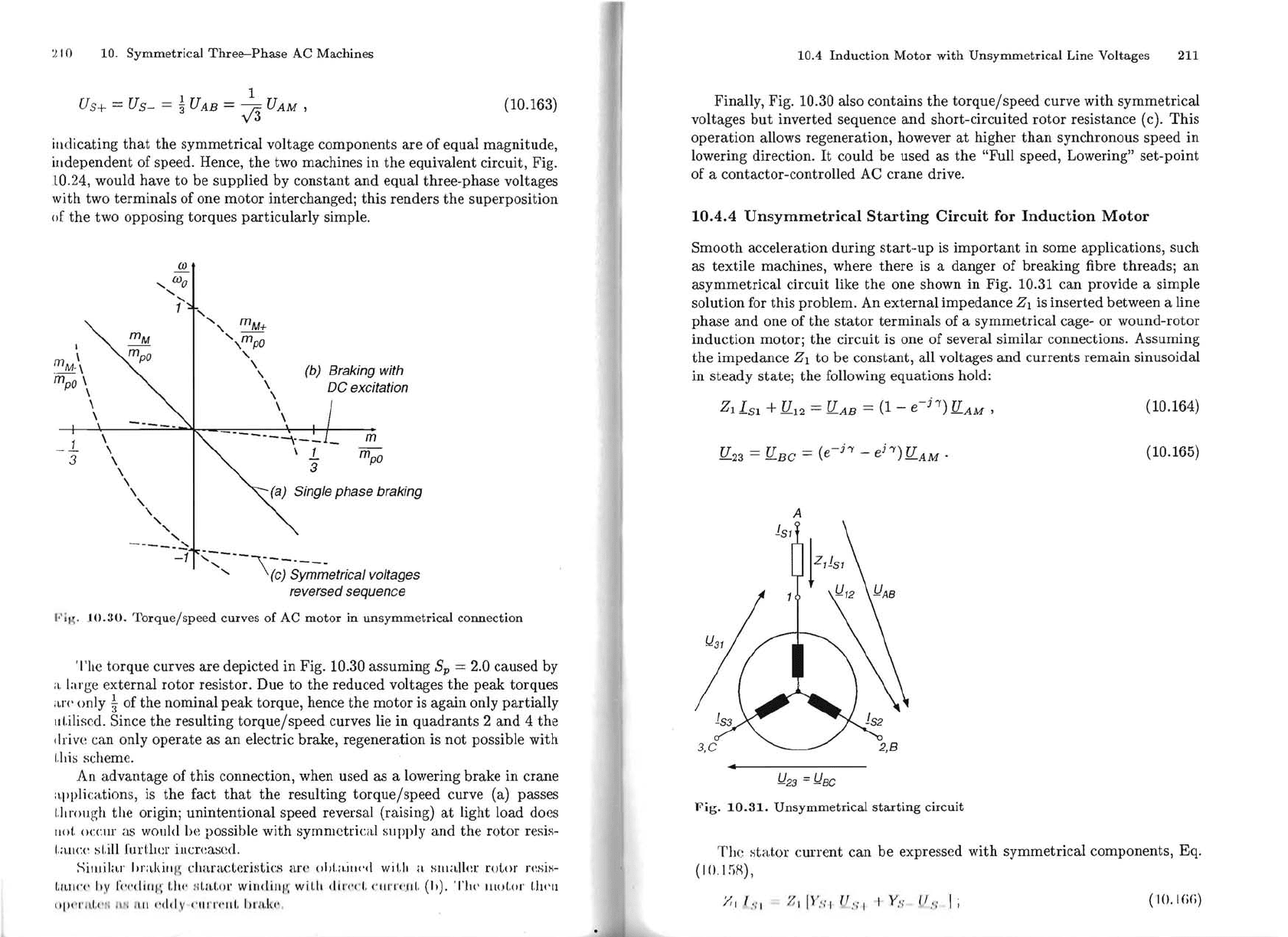
10.4.3
Single-phase
Electric
Brake
for
AC
Crane-Drives
Q
3
!l23
= O
Fig.
10.29.
Single
phase
supply
of
AC
motor
for
braking
duty
A simpIe
intermittent-duty
AC crane-drive required
to
operate
as elec
t.ri
...
brake
in
the
lowering direction may have
the
asymmetrical circuit
COllllec
~
tion shown in Fig.
10
.29, where two
stator
terminals
of
a symmetrical
wOIIJld
rotor
motor
with
large
rotor
resistor are short-circuited while single
-pha
H('
voltage is applied between
the
short-circuit connection
and
the
remaillillf
~
st
a
tor
terminal
[G23].
This
is one of several possible connections having silJli
lar properties.
The
analysis of
the
circuit is easy with
the
help
of
symm
etric
il.1
U
lInponcnts
.
J.llt,rodll<'ill{~
t.1l!:
c
Oll
st
raint
s
()f
t.
hc
circlIle
(/
I ::
/I
.·
111'
/I
'
.1
:1
.-
{)
(I().I(;~)
illl,
..
I'~q
t!
(III
H !,) ,
(10
I
Iii)
[,
":
11111.:
1
iII
4
10
10.
Symmetrical
Three-Phase
AC
Machines
1 _ 1
Us+ =
Us-
=
"3
UAB
-
-v'3
UAM
,
(10.163)
illdicating
that
the
symmetrical
voltage
components
are
of
equal
magnitude,
illdependent
of speed. Hence,
the
two machines
in
the
equivalent
circuit,
Fig
.
10.24,
would
have
to
be
supplied
by
constant
and
equal
three-phase
voltages
with
two
terminaIs
of one
motor
interchangedj
this
renders
the
superposition
(,f
the
two
opposing
torques
particularly
simple.
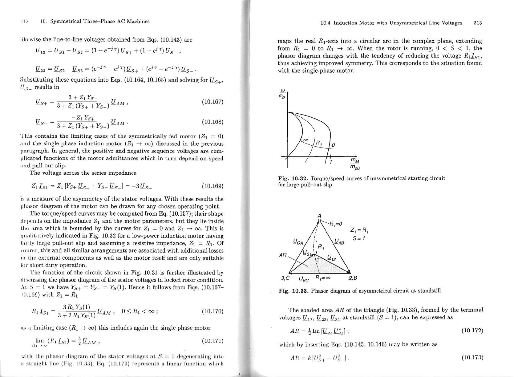
úJ
,
úJo
,
,
1
, -
" m
M
+
',m
po
I
\
m
M
. \
"
,
(b)
Braking
with
fn
po
\
\
De
exeitation
\
\
\
\
\
------"-\---
m
_
1.
\
\
1.
3
\
\
m
po
\
,
3
,
(a)
Single phase braking
,
,
,
,
,
-----~
-1
':'~--\;)S;m~etrieal
voltages
reversed sequenee
"'l
IJ:.
JO.30.
Torquejspeed
curves
of
AC
motor
in
unsymmetrical
connection
'l'he
torque
curves
are
depicted
in Fig. 10.30
assuming
Sp
= 2.0
caused
by
;\
. large
external
rotor
resistor.
Due
to
the
reduced
voltages
the
peak
torques
i
UT
only
kof
the
nominal
peak
torque,
hence
the
motor
is
again
only
partially
IIl.iliscd. Since
the
resulting
torquejspeed
curves lie
in
quadrants
2
and
4
the
drive
can
only
operate
as
an
electric brake,
regeneration
is
not
possible
with
I.I.is
scheme.
An
advantage
of
this
connection, when used as a lowering
brake
in
crane
applications, is
the
fact
that
the
resulting
torquejspeed
curve (a) passes
I.I.
rough
the
origin;
unintentional
speed
reversal (raising)
at
light
load
does
1101.
occur
as would
be
possible
with
symmetrical
supply
and
the
rotor
re
sis-
I.allcc
sLill
furl'.hcr illcreased.
SillJilar
hrakill
~
:
dmfacleris(,ics
aJ"(
~
liI/I.il.ill,'d with H
sllIaller
ro(,or
J"(~SiH-
1.1~1I1·"
11
'y
r,'('djllf
~
I,II!
' til,nl.ol" windiJlI{ wi
l.It
,11,
'
("<'1,
(' lI.rT
'·
.fJl.
(h).
TIl('
lIlol.or
1'''''
11
"1'
('1'11
1."
' 1 r
l'
i 1
111
\'
dd
,v
1'
111
('('
111.
I,rl
l.h
'.
10.4
Induction
Motor
with
Unsymmetrical
Line
Voltages 211
Finally,
Fig
. 10.30 also
contains
the
torquejspeed
curve
with
symmetrical
voltages
but
inverted
sequence
and
short-circuited
rotor
resistance (c).
This
operation
allows
regeneration,
however
at
higher
than
synchronous
speed
in
lowering direction.
It
could
be
used as
the
"Full speed, Lowering"
set-point
of
a
contactor-controlled
AC
crane
drive.
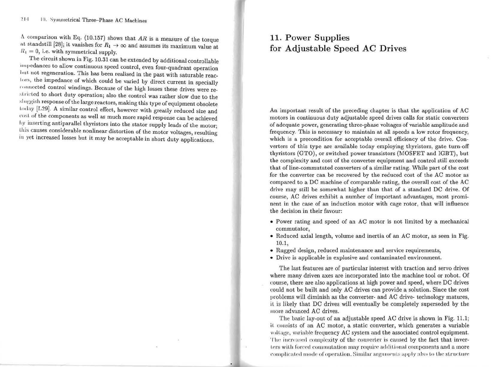
10.4.4
Unsymmetrical
Starting
Circuit
for
Induction
Motor
Smooth
acceleration
during
start-up
is
important
in
some
applications,
such
as
textile
machines, where
there
is a
danger
of
breaking
fibre
threadsj
an
asymmetrical
circuit
like
the
one shown
in
Fig. 10.31
can
provide a
sim
pIe
solution
for
this
problem.
An
external
impedance
ZI
is
inserted
between a line
phase
and
one of
the
stator
terminaIs
of a
symmetrical
cage- or
wound-rotor
induction
motor;
the
circuit is one
of
several
similar
connections.
Assuming
the
impedance
ZI
to
be
constant,
all volt ages
and
currents
remain
sinusoidal
in
steady
statej
the
following
equations
hold:
ZI
I
Sl
+ U
12
=U
AB
=
(1
-
e-h)
U
AM
,
(10.164)
U
23
= U
BC
=
(e-h
-
eh)
U
AM
.
(10.165)
A
!J
23
=
!Jae
Fig.
10.31.
Unsymmetrical
starting
circuit
The
s
tat.or
current
can
be
expressed
with
symmetrical
components,
Eq.
( I
O.
1
~H),
;;,
I ' :i I
;;,
I
1\',
.
,'
I
1/
,'
.
,'
I I Y·; (l
·.'
.I ;
(10. I (iii)
~!
I
~~
10.
Symmetrical Three-Phase
AC
Machines
likcwise
the
line-to-line voltages
obtained
from Eqs. (10.143)
are
U
12
= U
51
- U
52
=
(1
-
e-h)
U
5+
+
(1
-
eh)
U
5-
,
U
- U - U - (
-h
-
h)
U + ( h -
-h)
U
-23
-
-52
-53
- e e
-5+
e e
-5-
.
811bstituting these equations into Eqs. (10.164, 10.165)
and
solving for U5+'
lT.
s
_
results
in
U - 3 +
Zl
Y
s
-
U
(10.167)
-5+
- 3 +
ZI
(Ys+ +
Ys-)
-AM
,
u =
-Zl
Ys+
U.
(10.168)
-5-
3 +
Zl
(Y
s
+
+
Ys-)
-AM
'l'ltis contains
the
limiting cases
of
the
symmetrically fed
motor
(Zl
=
O)
aud
the
single phase
induction
motor
(Zl
-+
00)
discussed
in
the
previous
paragraph.
ln
general,
the
positive
and
negative sequence voltages
are
com-
plicated functions of
the
motor
admittances
which in
turn
depend
on
speed
and
pull-out slip.
The
volt age across
the
series impedance
Zl
I
S1
=
Zl
[Ys+
U
5+
+ Y
s
- us-l =
-3
u
5-
(10.169)
is
a measure
of
the
asymmetry
of
the
stator
voltages.
With
these results
the
phasor
diagram
of
the
motor
can
be
drawn for
any
chosen
operating
point.
Tlte
torquejspeed
curves
may
be
computed
from Eq. (10.157);
their
shape
dq)ends
on
the
impedance
Zl
and
the
motor
parameters,
but
they
lie inside
i.Ill~
:IIea
which
is
bounded
by
the
curves for
Zl
= O
and
Zl
-+
00.
This
is
qll:dil.atively indicated in Fig.
10.32 for a low-power induction
motor
having
I'ni
rly large pull-out slip
and
assuming a resistive impedance,
Zl
=
RI.
Of
('1111
rsp,
this
and
all similar
arrangements
are associated
with
additionallosses
iII t.hc
external
components as well as
the
motor
itself
and
are only
suitable
ror
short
duty
operation.
The
function of
the
circuit shown in Fig. 10.31 is
further
illustrated
by
I IiS!:\lssing
the
phasor
diagram
of
the
stator
volt ages in locked
rotor
condition.
AI,
8 = 1
we
have Y
s
+ =
Ys-
=
Ys(l).
Hence
it
follows from Eqs.
(10.167-
10.169)
with
Zl
=
RI
R I = 3
RI
Ys(l)
U
O
:S
RI
<
00
;
(10.170)
.
.L
-SI
3 + 2
RI
Ys(l)
-AM
,
as
a limit.ing case (RI
-+
00)
this
includes again
the
single phase
motor
hm
.'
(l{IL
";
I) =
'l
3
U
AM
,
(10.171)
U
1
H'XI
wil.11
1.11<'
1l11
1l
.'
:
oJ'
d i a
l'
/H
III
(Ir
thc
f
;l.a
l.or
vO!l.n
W·
!4
ai,
,<.,',
I d
q(
' 'II ('I't
ll.
i
111':
1
111,(1
:.
11
1.
1'
11
,1
1'
,
111.1
1
11
1
'
(
10'11
'
\'
IO
,:I:\)
1':'1
, (
10
, I'/(l)
1'
1'/11'1'1
11
'111,::
li
,
lilll'
llI'
1'
1I11.-1.i'lll
wil
ieh
10.4 Induction Motor with Unsymmetrical Line Volt
ages
213
maps
the
real
Rl-axis
into
a circular
arc
in
the
complex plane,
extending
from
RI
= O
to
RI
-+
00.
When
the
rotor
is running, O < 8 < 1,
the
phasor
diagram
changes
with
the
tendency
of
reducing
the
volt age
R1I
s1
,
thus
achieving improved symmetry.
This
corresponds
to
the
situation
found
with
the
single-phase motor.
úJ
úJ
o
o
mM
m
pQ
Fig.
10.32.
Torquejspeed curves of unsymmetrical starting circuit
for
large pull-out slip
A
{\--Rj=O
ZI=R
I
S=1
\AB
AR
3,C
R
I
=oo
2,8
!J
Be
Fig.
10.33.
Phasor diagram of asymmetrical circuit at standstill
The
shaded
area
AR
of
the
triangle (Fig. 10.33), formed by
the
terminal
voltages fl
12
, U
23'
~l
at
standstill
(8 =
1),
can
be
expressed as
AR
=
~
1m
[fl
23
U;ll
;
(10.172)
whjeh
hy
illsI'l'l.illl';
Eqs.
(10.145, 10.14ô) ma,y
be
written
as
ii
'"
I,;
III} 1
(!?,
I,
(10,'173)
"
;, I '1 I
()
. SymmetricaI
Three-Phase
AC Machines
A co
mparison
with Eq. (10.157) shows
that
AR
is a measure
of
the
torque
at
standstill
[28J;
it
vanishes for
Rl
-t
00
and
assumes its
maximum
value
at
/lI
=
O,
i.e.
with
symmetrical supply.
The
circuit shown in Fig. 10.31 can
be
extended by
additional
controllable
i
III
pedances
to
allow continuous speed control, even four-quadrant
operation
hlll.
llot regeneration. This has been realised
in
the
past
with
saturable
reac-
lo!s, the impedance
of
which could be varied by direct current
in
specially
c, >llllccted control windings. Because
of
the
high losses these drives were re-
~;I.!ictcd
to
short
duty
operation; also the control was
rather
slow due
to
the
si
11J';gi
sh response
of
the
large reactors, making this
type
of
equipment obsolete
I.<>day
[L29J.
A similar control effect, however
with
greatly reduced size
and
("os
I.
of
the
components as well as much more
rapid
response
can
be achieved
hy
ill
sc
rting
antiparallel thyristors into the
stator
supply leads
of
the
motor;
l.
!t
is
causes considerable nonlinear distortion
of
the
motor
voltages, resulting
i
II
yet increased losses
but
it
may
be
acceptable
in
short
duty
applications.
11.
Power
Supplies
for
Adjustable
Speed
AC
Drives
An
important
result
of
the
preceding
chapter
is
that
the
application
of
AC
motors in continuous
duty
adjustable speed drives calls for
static
converters
of
adequate
power, generating three-phase volt ages
of
variable
amplitude
and
frequency.
This
is necessary
to
maintain
at
all speeds a low
rotor
frequency,
which is a precondition for acceptable overall efficiency
of
the
drive. Con-
verters
of
this
type
are available
today
employing thyristors,
gate
turn-off
thyristors
(GTO),
or
switched power transistors
(MOSFET
and
IGBT),
but
the
complexity
and
cost
of
the
converter equipment
and
control still exceeds
that
of line-commutated converters
of
a similar rating. While
part
of
the
cost
for
the
converter can be recovered by
the
reduced cost
of
the
AC
motor
as
compared
to
a
DC
machine
of
comparable
rating,
the
overall cost
of
the
AC
drive
may
still
be
somewhat higher
than
that
of
a
standard
DC drive.
Of
course, AC drives
exhibit
a number
of
important
advantages,
most
promi-
nent
in
the
case
of
an induction
motor
with cage rotor,
that
will inftuence
the
decision
in
their
favour:
• Power
rating
and
speed
of
an
AC
motor
is
not
limited by a mechanical
commutator,
• Reduced
axiallength,
volume
and
inertia
of
an
AC
motor,
as seen in Fig.
10.1,
• Rugged design, reduced maintenance
and
service requirements,
• Drive is applicable in explosive
and
contaminated
environment.
The
last features are
of
particular
interest
with
traction
and servo drives
where
many
driven axes are incorporated into
the
machine tool or
robot.
Of
course, there are also applications
at
high power
and
speed, where
DC
drives
could
not
be
built
and
only AC drives can provide a solution. Since
the
cost
proLlems will diminish as
the
converter-
and
AC drive- technology
matures,
it is likely
that
DC
drives will eventually
be
completely superseded by
the
m
or
e
adv
anced AC drives.
Th
e basic lay-
out
of
an
adjustable speed AC drive is shown in Fig.
11
.
1;
iI.
collsists
of
an
AC
motor,
a
stati
c converter, which generates a variable
voU
.age, variable frequency AC system and
the
associated control equipment.
'I
'II<
: i
11(".)"(
':
1:-:
«:<1
col1Ipk
x:
it.y
of
th
e
c:onv
erter is callsed by
the
fact
that
inver-
I."I'
H
wil.h
fOI'( ·,'d
("()
li
11
11
II
Latio
l1
ma
y
n:q\lÍn
' :ul<lil.iollal component.s
and
a more
"o
l
lll'l
i" l
d,
,·d
IIIO.!"
01'
,,))("r
lt.
l,ioll.
Si
lllllll.l· I\1 1':
11111<'111.:
4 iI.l'l'l.v
al~o
1.0
1.1«:
SI,I"II<:
I.III'(
:
______
}I(i
11. Power Supplies for
Adjustable
Speed
AC Drives
'J'1I1,lc
11.1.
Adjustable
speed
AC drives, synopsis
UJ
1'1
tJ
'"'
W';3
°
e-
~
m
ç1
;.::::
~
8..<:1
13
2'~
13
u ". °
;,.,. 0
u
•
I H S
~
t) J;
13
Q)
....
..<:10
t-'
.~
Q)
-+J
<.J
~
H
;>
'>
I
e-
~§"'~
§
~
o
..<:1
U o.
~
~
..<:1
°
....,
UI,
. - S
ç1::;~~S
~t;O~o
.....
-
t-<
....,
U
::Jt::,CJ
~O)
UI;...·~;>
U
'"
tt1
I 8
o
ç1
tE
....
" o
,
1
"
-,
~
,.)
u
....
'
, n
'
-,
'
Q)
~
U
;
~
o
....
.
• I
~/
~
.
~I
I-'
;:
I
I
"
I ,
,,
'
I'
~'
Ü
~
U
r1
:~
íl
, ,
'--,
r
O
i).1
I"
:1
110
""'"
~
(I)
'
''
~
....
~
.
~
§
'
~
~
e-<
°
,...
....
--u
'"
J,
'1
'1
I:
'u
I-
(,,1
"
VI
V
O)
S s
....
~-ro~
~-:.
~~
~ro~
~iSal~
~~]~~~~~
0"",0.0.
0.,<:;
'"
• 0.2:.-::;
....
0.2: d
(fJ
..<:11.()~ç1
..<:1013].<::
~>,
bOo;'::::
Q)
.bOl.()
O"d
.~~
0.8
:::r::~.....:l
~2-
r;;.~~....:l"d
"d
o
o
o
o
bO
bO
(fJ
;:l
~
..
g
00
~~]
....
~
ç'
o.::
J; "
~
~
O)
o;>~..oo"",o.
....
""
~::g(j
....
o..~
VJ
Q).3
Q)
...c::
> o
-§,o~-5-§,gbO§S
~~$~~2-~9
;:l -
'"
I
....
O)
....
....
~
Q)
o
°
~
~
~
~oo_
o.iS
ô.-::;
"foiS
.~
o-----.:;..~
0...--::.
§
~
.&~
8
~
o.
'"
~ ~
2:
:.a2:~
32<..<:10
. -
.-<
bO"d
'"d
'-"'
......
.2~~
~§~
..<:1
(l)
"d
..<:1
~
O)
lJl
2:
O)
....
S~
....
g~
13
O)
....
'"
O)
~"d
m t) ;:l
~~"--::,",,.2~
~Ç'o
S..,;.a
....
~
8.~
al
~·C
0;>0
....
0Q)
~
~
2: o. o."d
0...>'<
bO.2
13 13
8
00
"'dO)
~oC~oo
0.0
3.-<..<:1
>,~
or-lQ)~;>~
.-<
;.a
V
bO
"d
ç1
.....:l~;>
.
~
~
'-'
Q)
-:B
ro
"a
~~o
"d
-
2: °
lJl
o~
bO
. 's
o
-s
r.l,+'
p'i.
te
~
~
w.;,
l
0',
I~
f1
,. ,
Ir
;
....
S ~
~
°
d
ç1
....,
(l)
°
>=l
~
°
ro
....
~
R
0
ç1
0.:
ç1
O)
V>
. 1-
,
--
'
....
....
....
.2
~
bO
o o
o v
ç1
....
d
ç1
.-
Õ I Õ
"d
o
>=lm"d
0)....,
~
dO)
....
>=l
bO
I
4-<
°
~
.-d
.§
§
t)
>")
H
.3
....
ç1
m
"d
...,+->
0-
IS'
o U
ç1
-"d
o
§
,?:l
t
'
.
;:Z~
;:j
~
§ 8
E
S
U
"'
O
o
~
..<:l
j;)"
~
u o
'ª
.~
I
~
O
~
I
],'~
.
~
o
..s
~
II
)
-
11. Power Supplies for
Adjustable
Speed
AC Drives
217
ContraI
Fig.
11.1.
General scheme of AC
motor
control
of
the
inner
torque
controlloop
which is much more complex
than
for a DC
motor.
The
reason
is
that
an
AC
motor
with its simple mechanical design
represents
an
involved nonlinear multivariable control
plant.The
motor
must
be fed with
alternating
currents of variable
amplitude,
frequency
and
phase;
in addition,
the
rotor
currents
cannot
be measured with ordinary cage motors.
This
is in
contrast
to
a DC machine, which has a very simple decoupled
control
structure
but
a more complex mechanical designo
The
mechanical
part
of
the
control scheme is,
apart
from
the
smaller
inertia
of
AC
motors,
the
sarne for DC-
and
AC-drives.
Fig. 11.2 indicates
that
the
mechanical
commutator
of a DC machine
acts like
an
electromechanical converter which feeds
the
armature
conduc-
tors
with
alternating
current
of a frequency
proportional
to
speed, Fig. 5.2 .
On
an
AC drive,
the
functions of current conversion
and
torque
generation
are mechanically separate,
thus
creating new options for electromechanical
interfaces .
Supply
DC - machine
/
~.--_.-.-._-----_.----
U
o
'
úJo
constant
Commutator
Line-sde
converter
1-
DC
- link
-----+-1
/
AC
-
motor
converter >
0
I
machine-side I W
....
____
---I.
UI'
úJ
I
L-
___
~
variable
I
~--------------
I
•
mM'
úJ
1
1
I
Fig.
11.2.
Controlled
AC-drive
with
DC-link
converter
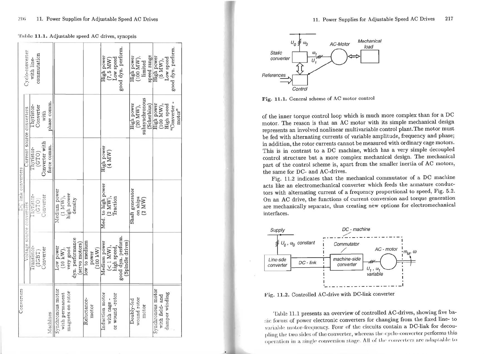
Table 11.1 presents
an
overview of controlled AC-drives, showing five ba-
:;ic fonns of power electronic converters for changing from
the
fixed line-
to
v;l.rial'](',
1I10Lor"
frcqm:ucy.
FOlll'
of til(: circuits contain a DC-link for decou-
1'1
i "I',
1.11('
I.W() :;id4'1 :
411'
I.!t\:
CO
\lVerLCT , w
114'1'(
';\:;
I
,
h(
~
cydo-collverter performs
this
"114'1
ii. Li
4111
iII
;
1.
:1
;111' .
.100
C'O\lVC'rnillll
:il,
;lI'.4'
f\
II
01'
1.
114'
4'nllvc'rl.4'l'
:-1
are
;t.dapl
,
;~hk
to
219
218 11. Power Supplies for
Adjustable
Speed AC Drives
four-quadrant
operation,
they
could also
be
used
with
variable speed genera-
t.ors, for
instance
in wind energy plants.
ln
the
vertical column
of
Table 11.1
li
ve basic
types
of
AC-machines
are
listed
that
may
be
used for controlled
dr
ives;
with
the
exception
of
the
reluctance
motor,
which is characterised by
salient poles,
they
can alI
be
treated
with
the
mathematical
model derived
iii
Sect. 10.1.
ln
principIe,
most
of
the
25
possible converter-machine combinations could
1)('
r
ea
lised
but
only those, where comments are entered, are presently applied
i
II
practice; since each
type
exhibits
particular
advantages,
it
is unlikely
that
I.h(' lield will eventually narrow to
just
one
or
two
major
circuits as has
been
t
.
It(~
case
with
DC-drives.
ln
fact, new combinations
may
be
added
as new
~;lViLcbing
devices
and
converter circuits
appear
on
the
scene. An example
of
Ih('
oIlgoing development
are
resonant-línk converters, presently
restricted
to
Imv
power applications such as switched mode power supplies; cyclo convert-
crs with forced
commutation
(matrix
converters)
are
also a possible
future
opLioll.
Only a
few
typical converter topologies
that
show promise
to
stay
\ViII
be discussed in this chapter.
11.1
Pulse
width
modulated
(PWM)
Volt
age
Source
Tr
ansistor
Converter
(IGBT)
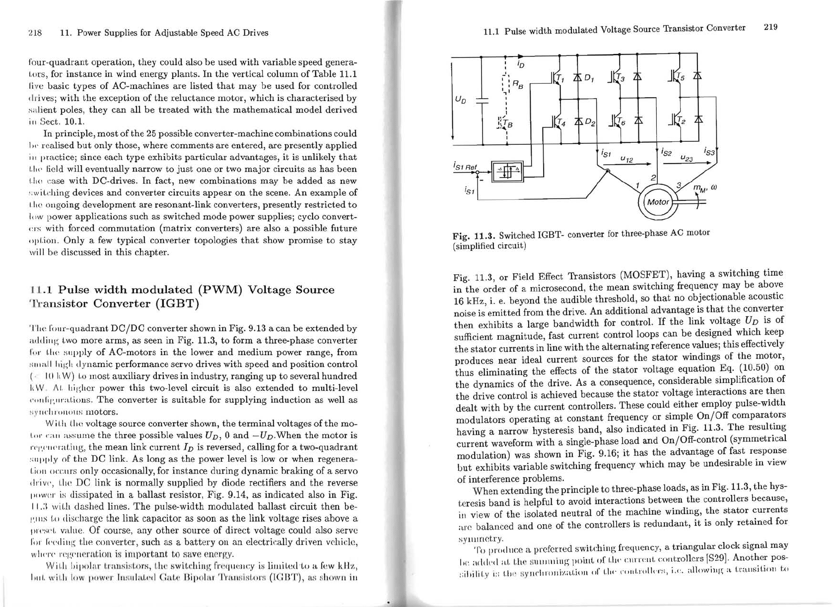
TI\(~
rOIlf-quadrant
DC/DC
converter shown
in
Fig. 9.13 a
can
be
extended
by
aclclillf~
\,wo
more
arms,
as seen in Fig. 11.3,
to
form a three-phase converter
fo
r 1."(' slIpply
of
AC-motors
in
the
lower
and
medium
power range, from
::11111.11
hiV;h
d'yl1amic performance servo drives with speed
and
position control
(. I
()
I,
W)
Lo
lIloSt auxiliary drives in industry, ranging up
to
several
hundred
li
'v
V,
II\.
Itil;hcr power
this
two-Ievel circuit is also extended to multi-leveI
('
oll/il',1I
r:l.t.iOllS.
The
converter is
suitable
for supplying induction as well as
Il
ylI('h
\(
)1l01lS
motors.
W
iLh
Cite
voltage source converter shown,
the
terminal
voItages
of
the
mo-
\'()f' (
';
\.11
assume
the
three possible values
UD,
O
and
-UD.When
the
motor
is
r('I'.(
·
II(
'l'
at.illg,
the
mean
link
current
I
D
is reversed, calling for a
two-quadrant
:;lIl'pl'y of
the
DC link. As long
as
the
power levei is low
or
when regenera-
Lioll
OCCIll'S
only occasionally, for instance
during
dynamic
braking
of
a servo
drive',
Lh
e DC link is normalIy supplied by diode rectifiers
and
the
reverse
I"
,wcr
is
clis
s
ipated
in a balIast resistor,
Fig
. 9.14, as indicated also
in
Fig.
I 1.:\ w
iLh
dashed lines.
The
pulse-width
modulated
ballast
circuit
then
be-
I'.IIIS
L()
di
schargc the link capacitor as soon as
the
link volt age rises above a
pr('s('\.
value.
Of
course, any
other
source
of
direct voltagc could also serve
1;)1
I'(
'(
'dillg t.hp converter, such as a
battery
011
an
electrically driven vehick,
wl\('re
r(~I
~:
('II(
~
rntion
is il1lJ)ortant
t.o
sav(
~
(m('rr~.Y.
Wi\.h
Il
ipolnr
t.mllsi s
t.!ll'K,
Lhe
:;wit.dlÍlI
~~
fr('qlwlI('.y
i:-;
lilllil.(~dto
n
r{
~
W
1\1
-
/(
"
IlIll.
\\'il.ll
low
1"'111'('1'
11I:;III:t.I,(
,
·cI
C a
L{'
1111'01
1
11
'
'
1'1'
1I.
1I1
1
íl~I
.
"
r
H
(leIIT),
H
:-i
:;
ho
w
lI
iII
11.1
Pulse
width
modulated
Voltage Source
Transistor
Converter
U
o
io
-',
: : R
B
" I
,
I
I'
,
I~TB
.....
I
I
i
SI
i
S2
iS3
Fig.
11.3.
Switched
IGBT-
converter for
three-phase
AC
motor
(simplified circuit)
i
SI
Fig. 11,3,
or
Field Effect
Transistors
(MOSFET),
having a switching
time
in
the
order
of
a microsecond,
the
mean
switching frequency
may
be
above
16 kHz, i.
e.
beyond
the
audible threshold, so
that
no objectionable acoustic
noise is
emitted
from
the
drive.
An
additional
advantage
is
that
the
converter
then
exhibits a large
bandwidth
for controI.
If
the
link volt age UD is
of
sufficient
magnitude,
fast
current
control loops can
be
designed which keep
the
stator
currents
in line
with
the
alternating
reference values;
this
effectively
produces
near
ideal
current
sources for
the
stator
windings
of
the
motor,
thus
eliminating
the
effects
or
the
stator
volt age
equation
Eq. (10.50) on
the
dynamics
of
the
drive. As a consequence, considerable simplification
of
the
drive control is achieved because
the
stator
voltage interactions
are
then
dealt
with
by
the
current
controlIers. These could
either
employ pulse-width
modulators
operating
at
constant
frequency
or
simple
On/Off
comparators
having a
narrow
hysteresis
band,
also
indicated
in
Fig. 11.3.
The
resulting
current
waveform
with
a single-phase load
and
On/Off-control (symmetrical
modulation)
was shown
in
Fig. 9.16;
it
has
the
advantage
of fast response
but
exhibits variable switching frequency which
may
be
undesirable in view
of interference problems.
When
extending
the
principIe
to
three-phase
loads, as
in
Fig. 11.3,
the
hys-
t.eresis
band
is helpful
to
avoid interactions between
the
controUers because,
in
vicw of
the
isolated
neutral
of
the
machine winding,
the
stator
currents
ar
e balanced
and
one of
the
controUers
is
redundant,
it
is only
retained
for
sylllmetry.
To
produce a prcfcrred switching freqllency, a
triangular
clock signal
may
Iw
added
aI.
LIt
~
~
\l\lJl\lillg
poillt
or
t.Jj('
cmrclIL cnntrollers [829].
Another
pos-
::ihilit
.y j::
1.1)(
,
>1
YII('hlOllj'l,aLwJI
(lI' UI('
(,
()IILIOII('\"
~:,
i.t:.
:dl()wiJli~
a
t,rallsj(.joll
to