Water and Wastewater Engineering
Подождите немного. Документ загружается.


11-26 WATER AND WASTEWATER ENGINEERING
Kawamura (2000) suggests that the depth of the filter bed follow the relationship shown in
Table 11-4 .
Filter Support and Underdrains
The underdrain system serves to support the filter medium, collect filtered water, and dis tribu te
backwash water and air scour if it is used.
Many filters use underdrain systems with openings larger than the filter medium to be sup-
ported. To prevent the medium
from leaking into the underdrain system, several layers of graded
gravel (called filter support ) are placed between the underdrain and the medium. GLUMRB’s
specifications when graded gravel is required are given in Table 11-5 .
There are five major categories of underdrain: manifold pipe system, bloc
ks, screens, false
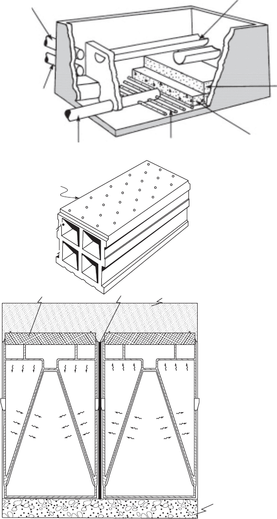
bottom with nozzles, and porous bottom. A few of these are illustrated in Figure 11-10 .
Pipe lateral underdrains were once popular because of their relatively low cost. Problems
with relatively high headloss and poor wash water distribution has resulted in a decline in their
use. Pipe lateral underdrains require
support gravel.
One common type of block is made with 6 mm diameter orifices on the top of the block. Sup-
port gravel is required for this type of underdrain to keep the media from being washed out of the
filter. Air scour may not be used with this system. A variation of this system uses polyethylene
blocks. Air scour can be incorporated in this block.
Media depth( )
Effective size( ),
D
E
or D/E Applications
1,000 Ordinary monosand and dual-media beds
1,250Typical tri-media beds (coal, sand, and garnet)
1,250–1,500
Coarse, deep, monomedium beds (
E 1.2 to 1.4 mm)
1,500–2,000
Very coarse, monomedium beds (
E 1.5 to 2.0 mm)
TABLE 11-4
Suggested media depth as a function of effective size
Data source: Kawamura, 2000.
TABLE 11-5
GLUMRB specifications for graded gravel
Source: Adapted from GLUMRB, 2003.
From the top layer down:
Torpedo sand: 8 cm depth, E 0.8 mm, U 1.7
Minimum of four gravel layers from the following:
Size range, mm Depth, mm
3–6 50–75
5–12 50–75
12–20 75–125
20–40 75–125
40–65 125–200
GRANULAR FILTRATION 11-27
Intel main
Wash water
outlet
Outlet main
(a)
Perforated pipe
laterals
Graded gravel
Graded
filter
sand
Wash troughs
Gravel
placed
on top
of
block
(b)
Sand
Concrete
(c)
IMS® cap
Grout
FIGURE 11-10
Filter underdrains: ( a ) perforated pipe laterals,
( b ) vitrified clay block, (c) Integral Media Support
(IMS
R
). In view ( c ): left is water flow during filtra-
tion, right is backwash flow pattern.
11-28 WATER AND WASTEWATER ENGINEERING
S creens are designed to be used without support gravel. Air scour may not be used with this
system.
The false bottom systems with nozzles are primarily used in filters using air/wash systems.
Fine openings in the nozzles eliminate the need for support gravel. This reduces the required
fil-
ter box depth in new designs and allows for deeper media depth in retrofit designs.
Porous bottom underdrains are constructed of aluminum oxide plates with very small pore
sizes. The pores are susceptible to plugging and are not suitable for softening or iron/manganese
removal plants.
The und
erdrain is a crucial feature of the filter design, and, in turn, it is crucial for the suc-
cess of the plant in removing turbidity before disinfection. It needs to be physically strong as well
as easy to install and maintain. None are free from disadvantages, but many problems can be
avoided by selec
tion of proven technology. Careful inspection during and after installation, but
also before placement of filter media, is essential.
The headloss during filtration or backwas hing is on the order of 0.1 to 0.3 m for modern
underdrains. The pipe and lateral system headloss d uring backwash may be as large as 0.6 m
(MWH, 2005). During filtration the
conduit losses will be negligible because the conduits are
sized to carry a backwash flow rate that is several times the filtration flow rate.
Backwashing
The need for backwash is indicated by one of three criteria:
• The headloss across the filter reac hes the maxim um design level or more customarily a
preset limit in the range of 2.4 to 3.0 m;
• The filtrate turbidity reaches a set upper limit;
• Or, some maximum time limit, usu
ally in the range of three or four days, has been reached.
The traditional backwash system in the United States is an upflow water wash with full bed
fluidization. Backwash water is introduced into the bottom of the bed through the underdrain sys-
tem. As the flow rate is increased, the entire bed expands. The backwash flow is c
ontinued until
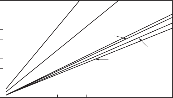
the wash water is reasonably clear. Figure 11-11 may be used to estimate an appropriate backwash
rate. Each degree Celsius increase in water temperature requires about a 2 percent increase in the
wash rate to prevent a reduction in bed expansion. The wash system should be designed for the
warmest wash water temperature that may be expected (Castro et al., 2005). Typical wash volumes
range from 4 to 8 m
3
of wash water/m
2
of surface area of the bed (Cleasby and Logsdon, 1999).
Storage capacity for two backwashes should be provided (Kawamura, 2000). GLUMRB (2003)
specifies that not less than 15 minutes of wash of one filter at the design wash rate be provided.
For sand filters, backwash flow rates range between 30 and 60 m/h for periods from 10 to
20 m
inutes (MWH, 2005). The limiting factor in choosing a backwash rate is the terminal set-
tling velocity of the smallest medium grains that are to be retained in the filter. Because the filter
backwashing process is effectively an upflow clarifier, the backwash rate becomes the overflow
rate that determines whether a particle is retained in the filter or is washed out throu
gh the back-
wash trough.
Another design criterion that is often used is to make sure that the largest, or the 90th percentile,
largest diameter particles are fluidized. In a dual-media filter, the d
90
of the anthracite is considered
GRANULAR FILTRATION 11-29
the largest-diameter particle. By fluidizing this particle during backwash, it will not “sink” to the
bottom of the filter and will restratify after the backwash is complete.
GLUMRB (2003) specifies that provisions shall be made for washing filters as follows:
• A minimum rate of 37 m/h consistent with water temperatures and the spe
cific gravity of
the media or;
• A rate of 50 m/h or a rate necessary to provide 50 percent expansion of the filter bed is
recommended or;
• A rate of 24 m/h for full depth anthracite or granular activated carbon media.
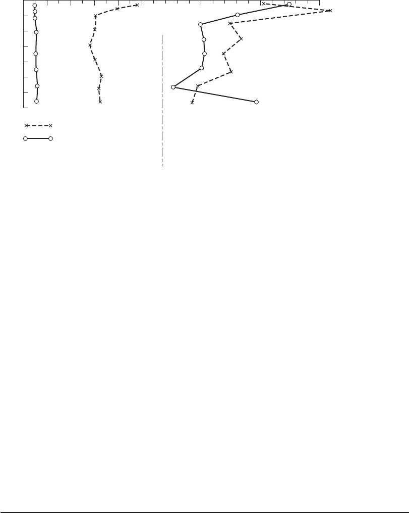
The alternatives for backwashing are (1) water-only backwash with a surface wash and
(2) water and air backwash (also known as
air scour ). As shown in Figure 11-12 , water back-
wash without surface scouring will not provide efficient cleaning of the bed.
Two basic types of surface wash systems are the fixed grid and rotating arms. Surface wash
systems inject jets of water into the surface from about 2.5 to 5 cm
above the surface. They are
operated for one to two minutes before the upflow backwash, and continue to operate until about
two to three minutes before the end of the upflow backwash. The surface wash systems have
been used for over 50 years and have proven effective. GLUMRB (2003) specifies that the water
pressure be at least 310 kPa and that the flow rate be 4.9 m/h with fixed nozzle
s or 1.2 m/h with
revolving arms.
Air scour systems supply air through the underdrain system. Though highly touted, the air
scour systems have not found universal favor. Kawamura (2000) reports that they agitate only the
top 15 to 25 cm of the bed and are not recommended when the filter bed is less
than 0.75 m deep
because a surface wash system can provide adequate cleaning. The air scour system complicates
the design and construction of the filter, requiring additional auxiliary equipment including air
blowers, air piping, and controllers. Air scour sy
stems require careful operation to avoid losing
0
0.2
0.4
0.6
0.8
1
1.2
1.4
1.6
1.8
2
0.0 0.5 1.0 1.5 2.0 2.53.0
60% Weight grain size, mm
Backwash rate, m/min
Garnet
S.G. ~ 4.0
Sand
S.G. ~ 2.60
Anthracite coal
S.G. ~ 1.70
S.G. ~ 1.65
S.G. ~ 1.60
S.G. ~ 1.55
FIGURE 11-11
G uide for backwash rate, water temperature 10 C. S.G. specific gravity.
11-30 WATER AND WASTEWATER ENGINEERING
filter med ium and potential movement of the gravel support medium (Cleasby and Logsdon,
1999). Kawamura (2000) and MWH (2005) recommend air scour systems when the media depth
exceeds 1 m.
For air scour systems, GLUMRB (2003) specifies an air flow of 0.9 to 1.5 m
3
of air/min · m
2
of filter area. In addition, the backwash flow rate must be variable from 20 to 37 m/h so that a
lower rate may be used when the air scour is on.
Backwash water has commonly been recovered and sent to the head end of the plant for
treatment because it may represent 1 to 5 percent of the total plant production. Thus, it is
a means of s aving water resource
s as well as chemical and energy costs in its production.
However, experimental evidence indicates that pathogenic cyst concentrations may build up to
such levels that these organisms breakthrough the filter (Cornwell and Lee, 1994). Subsequent
researc h has shown that treatment with polymers and s
ettling at conventional overflow rates
reduce the pathogen levels to those comparable with the raw water (Cornwell et al., 2001 and
LeGouellec et al., 2004).
Wash Troughs
Troughs may be made of fiberglass-reinforced plastic (FRP), stainless steel, or concrete. Because
they are less labor intensive to install, modern plants usually use manufactured “off-the-shelf”
FRP or stainless troughs. They have semicircular bottoms to create sm
ooth flow streamlines and
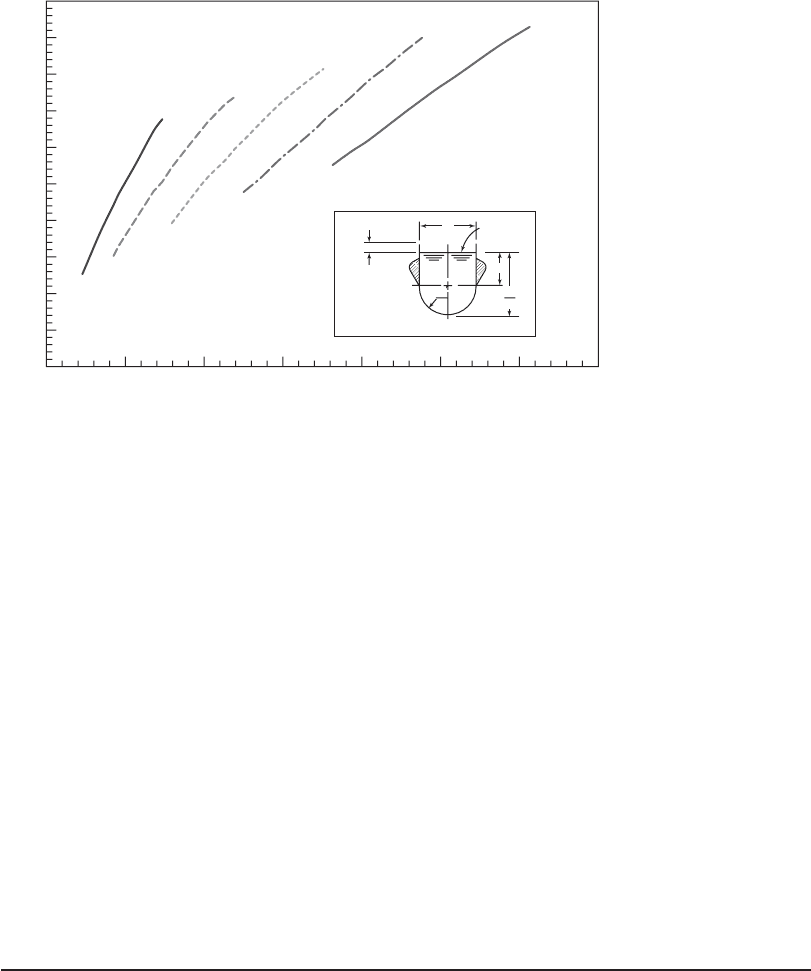
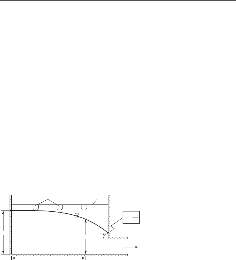
to prevent accumulation of foam and solids under the trough. The required cross-sectional dimen-
sions for a given wash water flow rate can be estimated from Figure 11-13 .
The d esign elevation of the weir edge of the trough may be estimated by adding the depth
required for maxi
mum bed expansion * a n d the d epth of the trough, plus a margin of safety of
200 400 600 800 1000
Turbidity, NTU
2000 3000 40000
0
10
20
30
40
50
60
70
Before filter wash
After filter wash
Prachin Buri WTP
(with surface wash)
Bang Moon Nak WTP
(no surface wash)
Depth from top of bed, cm
FIGURE 11-12
Sludge profile in filter beds. Amount of sludge is shown as turbidity (NTU).
( Source: Kawamura, 2000.)
* The targeted bed expansion for modern high-rate filters during backwash with surface wash is approximately 37 percent for a typi-
cal sand bed with a porosity of 0.45; the expansion for anthracite with a poro
sity of 0.5 is about 25 percent (Kawamura, 2000).
GRANULAR FILTRATION 11-31
0.15 to 0.3 m (Castro et al., 2005). When anthracite is used, Cleasby and Logsdon (1999) rec-
ommend that the distance to the top of the troughs from the surface of the filter bed should be
1.1 to 1.2 m.
GLUMRB (2003) recommends that
• The bottom elevation of the trough be above the m aximum level of the expanded media
during washing;
• A 5 cm freeboard inside the trough be provided;
• The top edge be level and at the same elevation for all troughs;
• The troughs be spaced so that each trough serves the same number of square meters of filter
area;
• The maximum horizontal travel of suspended particles to reach the trough not exceed 1 m.
For coal or dual media, troughs should be spaced 1.8 to 3 m apart (Kawamura, 2000).
It is critical that troughs be leveled uniformly to match a still water surface and that they be
properly supported both vertically and horizontally so that their weirs remain abs olutely level
d
uring backwashing. Center supports may be required for trough lengths over 4 m.
Example 11-6. Design the backwash system for Ottawa Island’s rapid sand filter. Use the fil-
ter dimensions from Example 11-5 . The backwash sy stem includes the layout of the backwash
troughs
, backwash velocity, volume of backwash water per trough, the trough dimension (width
and depth), trough elevation, volume of backwash tank, and elevation of the lowest water level
in the backwash tank.
0
0
5
10
15
20
25
30
35
40
45
50
200 400 600
Flow rate, m
3
/h
“Y”, cm
800 1000
Typical cross section
Based on
approximately
5 cm
Maximum
water
level
Y
Y +
W
2
1200 1400
W
2
W
W = 30 cm
W = 38 cm
W = 46 cm
W = 53 cm
W = 61 cm
FIGURE 11-13
Wash trough sizing chart.
11-32 WATER AND WASTEWATER ENGINEERING
Solution:
a . Using GLUMRB guidance, the wash troughs are to be spaced so that each trough serves
approximately the same number of square meters of filter area and so that the maximum
horizontal travel of suspended particles to reach the trough does not exceed 1 m.
U sing the sketch fro
m Example 11-5 , place wash troughs at intervals as shown below to
achieve an even spacing. As shown by the arrows, the max imum distance a suspended
particle must travel to a trough is 1.1 m. This does not meet the GLUMRB recommenda-
tion but is acceptable.
Gullet
2.6 m 2.6 m
5.5 m
1.1 m
0.8 m
0.8 m
0.8 m
0.8 m
1.1 m
0.6 m
Wash trough
Wash trough
Wash trough
b. From Example 11-3 , the backwash velocity is 864 m/d. This is equivalent to
864
24
36
m/d
h/d
m/h
This is slightly less than the GLUMRB recommended minimum of 37 m/h, but as noted
in Example 11-3 , this rate will avoid washing out the finest sand.
c. The maximum flow rate of backwash water per trough is at the end trough
()()( )36 2 6 1 1 0 8 177 8 180m/h mm m or m.. . .
33
/h
The distance of 1.1 m is from the end of the filter cell to the center line of the trough; the dis-
tance 0.8 m is from the midpoint between the two troughs to the center line of the trough.
U sing a backwash flow rate of 180 m
3
/h and Figure 11-13 , select a trough with di-
mensions W 30 cm and Y 23.5 cm. From the drawing in the figure, the depth of the
trough is 23.5 cm (30 cm/2) 5 cm 43.5 cm
d. The trough elevation is determined
from the backwash expansion calculated in Example 11-3 :
Height to the weir edge above undisturbedmeedia depth of trough
m
m
DD
e
015
07 05
.
..mm
0.15m or m
0435
0785 08
.
..
GRANULAR FILTRATION 11-33
e. The volume of backwash water for 15 minutes (0.25 h) of backwash is
()()()()()362 2655 025 257m/h cellsmm h... .. 4
3
m
Provide two times this volume or 514.8 or about 520 m
3
.
f. Assum ing a gravity feed, the lowest level of water the backwash tank should be 11 m
above the lip of the wash troughs (Kawamura, 2000).
Gullet
There are two gullets. The lower gullet carries the filtered water to the piping that leads to the
clear well. It will not be discussed. The upper gullet is the one generally recognized and the one
that is the focus of this discussion. It carries pretreated water to the filter and carries backwash
water and filter-to-waste water away for treatment and recycling through the plant.
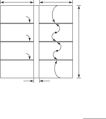
Flat-bottomed gullets ( Figure 11-14 ) m
ay be designed with the following equation (Camp,
1970; Hudson, 1981):
Hh
Q
gb h
ww
2
2
2
12
2( )
⎛
⎝
⎜
⎞
⎠
⎟
/
(11-20)
where H depth at upstream end, m
h depth at distance x in Figure 11-14 , m
Q
ww
wash water discharge, m
3
/ s
x length of gullet, m
g acceleration due to gravity, 9.81 m/s
2
b width of gullet, m
The upper elevation of H, the depth of wash water at the upstream end, is set below the bot-
tom of the wash troughs discharging into the gullet so that the wash trough discharge is a free fall.
The elevation of the bottom of the gullet (the lower elevation of H ) is highly variable. Various
authors show it at the bottom of the underdrain, at the bottom of the m edia, at som
e elevation
between the top and bottom of the media, and at the top of the media (Amirtharajah, 1978; Castro
et al., 2005; Kawamura, 2000; MWH, 2005, Reynolds and Richards, 1996).
H
h
x
v
Backwash
effluent
Backwash
troughs
Gullet
crest
>1.7
v
2
2g
FIGURE 11-14
Illustration of terms used for gullet design ( Equation 11-20 ).

11-34 WATER AND WASTEWATER ENGINEERING
A s noted in F igure 11-14 , the flow of backwash water out of the gullet controls the dimen-
sion h. The lowest feasible depth h at the outlet of the gullet is determined by the height of wash
water required to overcome the entry headloss into the outlet pipe (0.7 v
2
/2g) plus the velocity
head that is lost in producing the desired velocity in the pipe. The backwash conduit velocity is
generally in the range 1.2 to 2.4 m/s.
The wash water discharge, Q
ww
, is determined from the backwash rate and the area of the filter.
The solution is iterative. A trial value of b i s selected and the dimension H i s calculated. Mea-
suring from the bottom of the wash troughs, the depth is checked against one of the criteria noted
above. If the depth is greater than the depth to the bottom of the underdrain, it is too d
eep. If the bot-
tom of the gullet is above the media, the width may be too large. Depending on the size of the plant,
with smaller plants having smaller gullets, trial widths in the range of 0.4 to 2 m are suggested.
Example 11-7. Determine the gullet dimensions for Ottawa Island’s rapid sand filter. Use
the filter dimensions from Example 11-5 and the backwash rate from Ex
ample 11-6 . Assume a
450 mm diameter pipe from the gullet is to carry the wash water at a velocity of 1.8 m/s.
Solution:
a. Estimate the velocity head in the effluent conduit.
v
22
2
2
18
2981
0165 017
g
m/s
m/s
or m
()
()
.
.
..
b. As shown in Figure 11-14 , estimate the velocity plus entry headloss as
()
()
()
17
2
1718
2981
028
22
2
.
..
.
.
v
g
m/s
m/s
m
c. Calculate h.
h diameter of pipe velocity head entrance(hheadloss
mmm
)
h 045 028 073.. .
d. From Example 11-5 , assume a value of 0.6 m as a first trial for the width b and estimate
H using Equation 11-20 . Use the wash rate from Example 11-6 to estimate Q
ww
.
Q
ww
36 5 2 55
3 600
0 286
3
m/h mm
s/h
m /
()()..
,
. ss
m /s
m/s
/
H
12
2
3 2
2
073
2 0 286
981 0
()
()
()(
.
.
..
66073
07548 0 8
2
mm
or m
)( ).
..
⎡
⎣
⎢
⎢
⎤
⎦
⎥
⎥
H
This is 0.8 m below the bottom of the wash troughs. Using the depth of the trough from
E xample 11-6 , the initial estimate of the bottom elevation of the gullet is then
Depth depth of trough
mm
H
08 0435
1235
..
.orabout m below the lip of the wash125.trough
GRANULAR FILTRATION 11-35
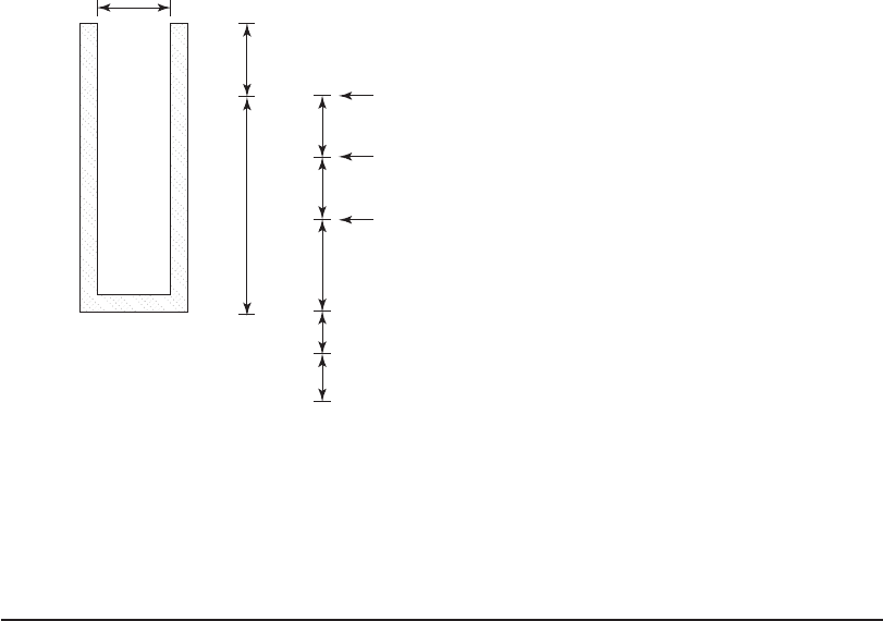
e. Check depth using height of backwash troughs estimate ( Example 11-6 ) and standard
depths for sand, gravel, and underdrain blocks.
• Height to the weir edge above undisturbed media 0.8 m
• Depth of sand 0.6 m
• Depth of gravel 0.3 m
• Depth of underdrain block 0.3 m
From the sketch shown below, the bottom of the gullet will be approximately at the same
elevation as the bottom of the gravel support. This is within the guidelines (between the
top of the media and the bottom of the underdrains).
Gullet
0.5 m
0.5 m
1.25 m
0.4 m
0.4 m
0.6 m Sand
0.3 m Gravel
0.3 m Underdrain bloc
k
Top of trough
Top of media
Bottom of trough
H
Comments:
1 . The actual depth of the gullet will be a little deeper because the gullet wall surrounds the
backwash trough and extends slightly above it to provide a firm support. This distance is
on the order of 0.5 m.
2. The initial estimate of the wid th of the gullet of 0.6 m from Exam ple 11-5 is the final
width. The depth from the top ed
ge to the bottom of the gullet is about 1.75 m
Flow Apportionment and Rate Control
The three basic methods for controlling the filtration rate and distributing the flow to the filters
are a modulating control valve system, influent weir splitting, and declining-rate filtration.
The modulating control valve system is equipped with a flow meter and a control valve. Each
filter has a flow meter, or a level transmitter and a controller. The control valve apportions the flow
to balance the flows to each filter. As filters are taken out of
service for backwashing or repair, the
controller adjusts the flow. An advantage of this system is that it allows water to flow smoothly
to the filters without weirs or orifices, thus, minimizing floc breakup. The disadvantage is that