Water and Wastewater Engineering
Подождите немного. Документ загружается.

10-20 WATER AND WASTEWATER ENGINEERING
be uniform across the cross-sectional area of the tank as it enters the settling zone. The inlet
pipe carrying solids to the clarifier often is designed to have velocities high enough to keep the
particles from settling in the pipe. This high velocity must be reduced sufficiently to prevent jet
effects in the basin. The design solution is to provide a diffu
ser wall and, perhaps, an inlet baffle
(also known as a target baffle ).
Density Currents. Short-circuiting i s the term used to describe the effect of density currents
on settling tank performance. Short-circuiting occurs when the flow through the tank is not uni-
form and a current carries the particulate matter to the effluent launders before the particles can
settle. Te
mperature differentials and changes in solids concentration are major causes of density
currents.
The addition of warm water to a sedimentation basin, or the warming of the surface water in
a basin containing cooler water, leads to short circuiting because the warmer water rises to the
surface and reaches the laund
ers in a fraction of the theoretical detention time. Conversely, the
cooler water tends to dive down, flow along the bottom, and rise at the tank outlet. Temperature
density currents are commonly caused by exposure to sunlight, changing the mixing ratio of two
or more water sou rces, switching from one source to another, and shifting the re
servoir intake
elevation.
A rapid increase in the influent solids concentration from floods or high winds on lakes and
reservoirs will cause a higher density in the influent than in the basin. This will cause it to plunge
as it enters the basin, flow along the bottom, and rise at the tank outlet. Intermediate diffuser
walls have been used to counteract densit
y current effects.
Wind Effects. Large, open tanks are susceptible to induced currents and, in sufficiently strong
winds, waves along the top of the tank. An underflow current in the opposite direction to the sur-
face current is also created. In addition to short circuiting, this may lead to scouring of the already
settled particulate
matter from the sludge zone. The design solutions include limiting the length
of the tank and placing wave breakers along the tank surface.
10-3 SEDIMENTATION PRACTICE
Alternatives
T ypical sedimentation tanks used in water treatment are listed in Table 10-1 . Of those listed, the
recommended ord er of preference for settling coagulation/flocculation floc is (1) a rectangular
tank containing high-rate settler modules, (2) a long rectangular tank, and (3) a high-speed mic-
rosand clarifier (also known as ballasted sand sed
imentation ). For the lim e-soda softening pro-
cess, the upflow solids contact unit (also known as a reactor clarifier or sludge blanket clarifier)
is preferred.
The upflow and upflow, solids-contact clarifiers are proprietary units that have their basic size
and blueprints preestablished by the equipment manu
facturers. They are not preferred for remov-
ing alum floc for the following reasons: (1) temperature fluctuations as small as 0.5 C can cause
severe density flow short circuiting, and (2) there is a rapid loss of efficiency if there is hydraulic or
solids overloading. There are circumstances when they
may be appropriate. These are discussed in
detail by Kawamura (2000). Horizontal flow with center feed, peripheral feed, and simple upflow
clarifiers are not recommended because of their hydraulic instability (Kawamura, 2000).
SEDIMENTATION 10-21
With the exception of the upflow solids contact unit that was discussed in Chapter 7, the
remainder of this discussion will focus on the preferred alternatives.
Rectangular Sedimentation Basins. Current design practice is shifting from rectangular sedimen-
tation basins to high-rate settler modules or, in some cases, dissolve
d air flotation (DAF). The rectan-
gular sedimentation basin design is presented here because, historically, it has been the most frequently
used design and because it serves as the fundamental structure for high-rate settler modules.
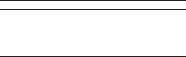
A rectangular basin with horizontal flow is s
hown in Figure 10-13 . To provide redundancy,
two basins are placed longitudinally with a common wall. The inlet structure is designed to dis-
tribute flocculated water over the entire cross section. Outlet structures for rectangular tanks
generally include launders placed
parallel to the length of the tank. Cross baffles may be added to
prevent the return of surface currents from the end of the tank back toward the inlet.
Generally, sludge is removed by mechanical collectors. The major types of mechanical col-
lectors ranked in order of cost are: (1) a traveling bridge with sludge-scraping squ
eegees and a
mechanical cross collector at the influent end of the tank, (2) a traveling bridge with sludge suc-
tion headers and pumps, (3) chain-and-flight collectors, and (4) sludge suction headers supported
by floats and pulled by wires (MWH, 2005).
A s may be im
pled from its title, the traveling bridge system consists of a bridge across the
width of the tank that travels up and down the tank on wheels resting on the tank wall or side
rails. Either scraper blades or a suction device is suspended from the bridge to the slu dge zone.
The suction system is equipped with either a pu
mp or it makes use of a siphon effect from the
differential head between water levels in the clarifier and the sludge line to remove the sludge.
For water treatment systems, the pump system is preferred.
The chain-and-flight system consists of two strands of chain on either side of the collection
area with “flights” running across
the width of the collection area. The flights, formerly made of
redwood, and now made of fiberglass reinforced composite, are attached at 3 m intervals. High
density polyethylene (HDPE) wearing shoes are attached to the flights. These ride on T-rails cast
into the concrete floor. The chain and sprocket drive, formerly ma
de of steel, is now made of a
high-strength composite material. Although the chains are corrosion free and require less mainte-
nance, they have a tendency to stretch when first installed.
A cross collector, or hopper, is placed at the influent end of the tank. Sludge is scraped to the
end of the tank and pushed into the hopper.
TABLE 10-1
Alternative settling tank configurations
Nomenclature Configuration or comment
Horizontal flow Long rectangular tanks
Center feed Circular, horizontal flow
Peripheral feed Circular, horizontal flow
Upflow clarifiers Proprietary
Upflow, solids contactRecirculation of sludge with sludge blanket, proprietary
High-rate settler modules Rectangular tank, parallel plates or tubes, proprietary
Ballasted sand Addition of microsand, proprietary
A dapted from Kawamura, 2000.
10-22 WATER AND WASTEWATER ENGINEERING
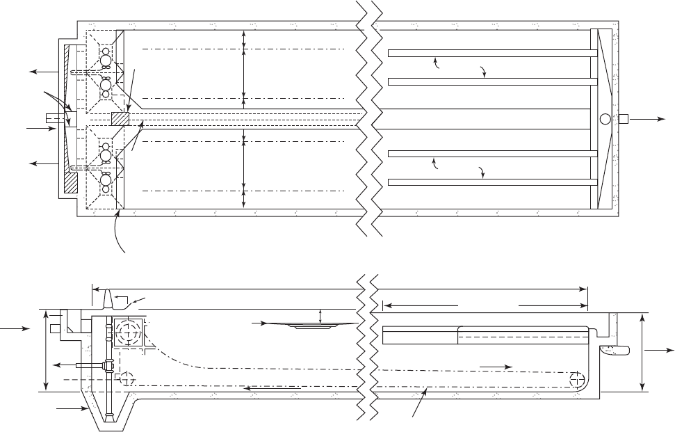
High-Rate Settler Modules. The modules are placed in the downstream end of rectangular
horizontal flow tanks below the launders as shown in Figure 10-14 . They occupy approximately
75–95 percent of the tank area. The remaining area is left as open space. As with the rectangular
sedimentation bas in, a diffuser is placed at the inlet. A solid baffle wall
covers the entire front
end of the settler if the flow is countercurrent. Sufficient s pac e is provided below the settler for
the sludge collection mechanism.
Although special accommodations may be made for other types, the chain-and-flight or
indexing grid sludge collection syste
m is frequently employed because the settler modules would
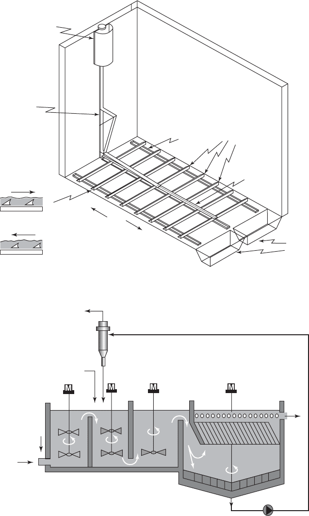
interfere with any of the other collection mechanisms. The indexing grid system ( Figure 10-15 ) on
page 10-24 consists of a series of concave-faced triangular blades rigidly connected to glid
e bars.
The glide bars ride on top of polyethylene wear strips anchored to the floor of the tank. The system
operates at the bottom of the sludge layer. The collector operates by gently pushing the grid sys-
tem and the sludge in front of the grid at a speed between 0.6 and 1.2 m/min. When the hydraulic
cylinder that drives the grid reaches
the end of its stroke, the grid system reverses at two to three
times the forward speed. During the return movement, the triangular shaped blades slide under the
sludge so that there is minimum disturbance to the sedimentation process. The result is a continuous
Sludge
Stop gates
Sludge
Influent
Influent
Effluen
t
Launder
Launder
Effluent
Opening in floor
for drive chain
(a) Plan view
Diffuser wall
Sludge
Min slope 45
°
Max water level
Chain tightener
Tank length
Free board
(b) Profile
Tank depth
Chain for chain-and-flight collector
Tank depth
Equipment
symmetrical
about center line
of drive
Tank width
Walkway
Effluent weirs
of chain & tee rails
C
L
of chain & tee rails
C
L
C
L
of chain & tee rails
C
L
of chain & tee rails
C
L
FIGURE 10-13
( a ) Plan and ( b ) profile of horizontal-flow, rectangular sedimentation basin.
SEDIMENTATION 10-23
movement of the sludge to a crosscollector at the end of the tank. The location of the drive system
above the water and the minimization of moving parts in the sludge blanket are suggested operation
and maintenance advantages of the indexing system.
Alternatively, the settler sys tem may be designed to accommodate a traveling bridge if a
traveling bridge is selected early in the design process. Because of the travel speed of the traveling
bridge, only the pump type for removing the solids is appropriate.
Ballasted Sedimentation. These are proprietary units. A schematic of a typical unit is shown
in Figure 10-16 . Alum or ferric chloride is added in the first stage to for
m turbidity floc. Sub-
sequently, a high-molecular-weight cationic polymer and microsand particles are added to the
Diffuser wall
0.05L to 0.25L
L
0.75L to 0.95L
24 m max
Influent channel
Chain-and-flight system
V-notch weir plate
Tube settler module
(b)
(c)
(a)
Sludge pipe
~ 0.6 m
~ 0.5 m
0.5 to 2 m for plate settler
2.0 m minimum
May not need with
plate settler
Weir plate
Launder
Sludge collector
Solid bafflewall
(entire front end)
Flow
(Covered with settler)
Effluent
channel
La
under trough (typical)
Longitudinal baffle wall
Settlers
Diffuser wall
FIGURE 10-14
S e dimentation tanks with tube settler modules: ( a ) plan; ( b ) elevator; ( c ) typical dimensions in m. Plate settlers
may be deeper than tube settlers and in some proprietary types, may have an integrated launder.
10-24 WATER AND WASTEWATER ENGINEERING
Coagulation
Raw
water
Coagulant
Hydrocyclone
Polymer
Microsand
Sludge
Ballasted Flocs
to Hydrocyclone
Clarified
water
Maturation
Tube settler
with scraper
Injection
FIGURE 10-16
ACTIFLO ballasted sedimentation process for water treatment. ( Courtesy of Kruger Inc. )
Sludge hoppers
Drive shaft
Scraper plow
Wear strip
Hydraulic drive
cylinder
Drive
elbow
Pu
s
h
Ret
u
rn
Exploded view
Push
Return
FIGURE 10-15
I n dexing grid sludge scraper.
SEDIMENTATION 10-25
second stage. These flocculate with the preformed turbidity floc. After flocculation, the ballasted
floc is settled in a high-rate settler, and the slud ge is pumped to a hydrocyclone where the mic-
rosand is recovered for reuse.
The surface loading rate ranges from 35 to 62 m/h. The floc settling velocities
are 20 to
60 times greater than conventional sedimentation. This allows a reduction in detention time to
between 9 and 10 minutes. The sludge contains 10 to 12 percent sand by weight.
10-4 SEDIMENTATION BASIN DESIGN
R e ctangular tank and high-rate settlers are the primary focus of this discussion. Because ballasted
sedimentation is a proprietary process, the design is under the control of the manufacturers. The
design of this process will not be covered.
Rectangular Sedimentation Basins
At a minimum, to provide redundancy, two tanks are provided. These are placed together, in
parallel, with a common wall. In general, four tanks are preferred (Willis, 2005). This provides
maximum flexibility in operation over a wide range of flow rates with allowance for one unit be-
ing out of service at the maximum flow rate. Four tanks, however, may result in an unacceptable
capital cost.
Inlet Zone. The preferred arrangement is a direct connection between the flocculation basin
and the settling tank. The diffuser wall between the two tanks is designed using the same proce-
dure that was used for baffle walls in flocculation tanks (Chapter 6).
When the flocculated water must be piped to the settling tank, the flow velocity commonly
used is in the range of 0.1
5 to 0.6 m/s. This velocity must be reduced and the flow spread evenly
over the cross section of the settling tank. A diffuser wall is the most effective way to accomplish
this. The design process is the same as that used for baffle walls in flocculation tanks (Chapter 6).
The diffuser wall is place
d approximately 2 m downstream of the inlet pipe. The headloss
through the holes should be 4 to 5 times the velocity head of the approaching flow. Port velocities
typically must be about 0.20 to 0.30 m/s for sufficient headloss. The holes are about 0.10 to 0.20 m
in diameter spaced about 0.25 to 0.60 m apart. They
are evenly distributed on the wall. The lowest
port should be about 0.6 m above the basin floor (Willis, 2005).
Settling Zone. Overflow rate is the primary design parameter for sizing the sedimentation ba-
sin. Typical overflow rates are given in Table 10-2 . These rates are usually conservative enough
that the inlet zone does not have to be added to the length calculated for the settling zone. If the
overflow rate is base
d on pilot studies, then the length of the inlet zone is added to the length
calculated from the overflow rate.
In theory the sedimentation basin depth [also called side water depth (SWD)] should not
be a design parameter because removal efficiency is based on overflow rate. However, there is
a practical minimum d epth required for sludge rem
oval equipment. In addition, depth may be a
controlling parameter to limit flow-through velocities and/or scour of particles from the sludge
blanket. Basins with mechanical sludge removal equipment are usually between 3 and 5 m deep
(MWH, 2005, and Willis, 2005).
To provide plug flow and minimize
short circuiting, a minimum length to width ratio (L:W)
of 4:1 is recommended. A preferred L:W is 6:1 (Kawamura, 2000).

10-26 WATER AND WASTEWATER ENGINEERING
Open sedimentation tanks greater than 30 m in length are especially susceptible to wind effects.
For longer tanks, wave breakers (launders or baffles) placed at 30 m intervals are recommended.
The tank depth is usually increased by about 0.6 m to provide freeboard to act as a wind barrier.
Horizontal flow velocities m
ust be controlled to avoid undue turbulence, bac kmixing, and
scour of particles from the sludge. GLUMRB (2003) recommends that the velocity not exceed
0.15 m/min. Velocities of 0.6 to 1.2 m/min have been found to be acceptable for basin depths of
2 to 4.3 m (Willis, 2005). Reynolds and
Froude numbers can be used to check on turbulence and
backmixing. The Reynolds number is determined as
R
vR
fh
(10-32)
where R Reynolds number, dimensionless
v
f
average horizontal fluid velocity in tank, m/s
R
h
hydraulic radius, m
A
s
/ P
w
A
s
cross sectional area, m
2
P
w
wetted perimeter, m
kinematic viscosity, m
2
/ s /
dynamic viscosity, Pa · s
density of fluid, kg/m
3
The Froude number is determined as
Fr
()v
gR
f
h
2
(10-33)
where Fr Froude number, dimensionless
g acceleration due to gravity, 9.81 m/s
2
TABLE 10-2
Typical sedimentation tank overflow rates
a
Application Long rectangular and circular,
m
3
/d · m
2
Upflow solids-contact,
m
3
/d · m
2
Alum or iron coagulation
Turbidity removal 40 50
Color removal 30 35
High algae 20
Lime softening
Low magnesium 70 130
High magnesium57105
a
These rates are guides that are applicable at moderate water temperatures—not less than 10 C. For lower
temperatures the rates should be reduced.
Source: Adapted from AWWA, 1990.
SEDIMENTATION 10-27
Recommended values for the settling zone design are R < 20,000 and Fr > 10
5
( Kawamura,
2000). A large Reynolds number indicates a high degree of turbulence. A low Froude number
indicates that water flow is not dominated by horizontal flow, and backmixing may occur. Like
all design criteria, these values are based on experience. While the desired Reynolds number i
s
relatively easy to achieve by modifying the tank shape, the recommended Froude number is very
sensitive to the shape of the tank and is difficult to achieve while maintaining other design crite-
ria when the flow rates are under 40,000 m
3
/ d.
The Reynolds number may be reduced and the Froude number increased by the placement of
baffles parallel to the direction of flow. The baffles must be placed above the sludge collection
equipment and should be about 3 m apart (MWH, 2005).
GLUMRB (2003) recommends a minim
um of four hours detention time or an overflow rate
not to exceed 1.2 m/h. This appears to be a carryover from the time when basins were manually
cleaned and were designed with depths of 5 m or more to store large volumes of sludge between
cleaning. Thus, more than half the volume could be filled with sludge before cleaning wa
s re-
quired, and real detention times could vary from four hours when the tank was clean to less than
two hours just before cleaning. Modern designs do not provide for this large of a storage zone,
and detention times of 1.5 to 2.0 h have proven to provide excellent treatment (Willis, 2005).
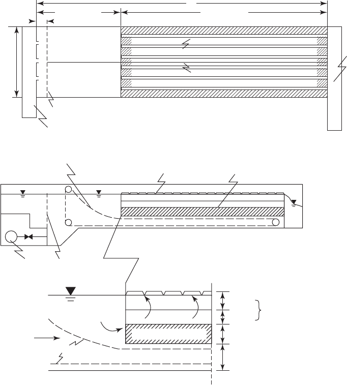
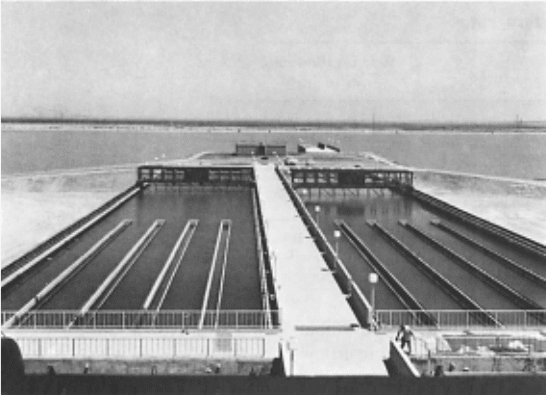
Outlet Zone. The outlet zone is composed of laun
ders running parallel to the length of the
tank. The weirs should cover at least one-third, and preferably up to one-half, the basin length. As
shown in Figure 10-17 , they are spaced evenly across the width of the tank. If baffles are used, a
launder is placed midway between the baffles. Long weirs have three advantages: (1) a gradual
reduction of flow velocity toward the end of the tank, (2) m
inimization of wave action from wind,
and (3) collection of clarified water located in the middle of the tank when a density flow occurs.
The water level in the tank is controlled by the end wall or overflow weirs. V-notch weirs
are attached to the launders and broad-crested weirs are attached to the end wall. Submerged
FIGURE 10-17
Launders in horizontal-flow rectangular sedimentation tanks.
10-28 WATER AND WASTEWATER ENGINEERING
orifices may be used on the launders. These have been used to avoid breakup of fragile floc when
conventional rapid sand filters are used. For high-rate filter designs, there is less concern about
breaking the floc because high-rate filters require a small strong floc, and filter aids are added
prior to filtration to improve particle attachment in the filter.
Although the optimum weir hydraulic loading rate is dependent on the design of prior and
subsequent processes, typical weir loading rates are given in Table 10-3 . GLUMRB (2003) speci-
fies that the hydraulic load ing shall not exceed 250 m
3
/ d · m of outlet launder, that submerged
orifices should not be located lower than 1 m below the flow line, and that the entrance velocity
through submerged orifices shall not exceed 0.15 m/s. Research has shown that loading rates may
be as high as 1,000 m
3
/ d · m of weir given a reasonable water depth (AWWA, 1990).
Sludge Zone. In selecting the depth of the sedimentation tank, an allowance of between 0.6 and
1 m is made for sludge accumulation and sludge removal equipment. If the overflow rate design
is based on pilot studies, then the depth of the pilot settling column used to develop the data may
be sele
cted as the depth of the tank. In this case an additional 0.6 to 1 m is added to the column
depth to account for the sludge zone.
To facilitate sludge removal, the bottom of the tank is sloped toward a sludge hopper at the
head end of the tank. When mechanical equipment is used, the slope should be at least 1:600.
Chain-and-flight c
ollectors are commonly employed to remove the sludge. Their length is
limited to about 60 m. The flight widths are provided in 0.3 m increments and are limited to a 6 m
width between the chains. However, up to three trains in parallel (24 m maximum width) may be
placed in one settling basin (Kawamu
ra, 2000). The velocity of chain-and-flight scrapers should
be kept to less than 18 m/h to prevent resuspending settled sludge.
Unlike chain-and-flight collectors, traveling bridge collectors can service extremely long tanks.
They are more cost effective if the basin length exceeds 80 to 90 m, and the width exceeds 12 m
.
They can span up to 30 m (Kawamura, 2000). For suction sludge removal units, the velocity can be
as high as 60 m/h because the concern is disruption of the settling process, not the resuspension
of sludge.
The cross collector is typically 1 to 1.2 m
wide at the top and about 0.6 to 1.2 m deep. Either
a helicoid screw or a chain-and-flight mechanism is used to move the sludge across the hopper to
a hydraulic or pumping withdrawal. Traditionally, the hopper is steep-sided at an angle of about
60 (Willis, 2005).
TABLE 10-3
Typical weir hydraulic loading rates
Type of floc Weir overflow rate, m
3
/d · m
Light alum floc
(low-turbidity water) 140–180
Heavier alum floc
(higher turbidity water) 180–270
Heavy floc from lime softening 270–320
Source: Davis and Cornwell, 2008.

SEDIMENTATION 10-29
Horizontal-Flow Rectangular Sedimentation Basin Design Criteria
T ypical design criteria for horizontal-flow rectangular sedimentation basins in larger water treat-
ment plants ( 40,000 m
3
/ d) are summarized in Table 10-4 . Some design criteria are quite rigid
while others only provide guidance. For example, because of manufacturing constraints, the
length of a chain-and-flight collection sets a firm maximum on the length of the settling basin.
Although the maximum width i
s 6 m, multiple units may be mounted in parallel to achieve
widths up to 24 m.
E xample 10-4 illustrates the design of a horizontal-flow rectangular sedimentation basin
based on the results of a pilot column study.
For design criteria for medium to small plants (
40,000 m
3
/ d) see the discussion following
E xample 10-4 .
TABLE 10-4
Typical design criteria for horizontal-flow rectangular sedimentation basins
Parameter Typical range of values Comment
Inlet zone
Distance to diffuser wall 2 m
Diffuser hole diameter 0.10–0.20 m
Settling zone
Overflow rate 40–70 m
3
/d · m
2
See Table 10-2
Side water depth (SWD) 3–5 m
Length 30 m Wind constraint
60 m Chain-and-flight
80–90 m Traveling bridge
Width 0.3 m increments Chain-and-flight
6 m maximum per train Chain-and-flight
24 m maximum 3 trains per drive Chain-and-flight
30 m maximum Traveling bridge
L:W 4:1 to 6:1 6:1 preferred
L:D 1
5:1 Minimum
Velocity 0.005–0.018 m/s Horizontal, mean
Reynolds number < 20,000
Froude number > 10
5
Outlet zone
Launder length 1/3–1/2 length of basin Evenly spaced
Launder weir loading 140–320 m
3
/d · m See Table 10-3
Sludge zone
Depth 0.6–1 m Equipment dependent
Slope 1:600 Mechanical cleaning
Sludge collector speed 0.3–0.9 m/min
Sources: AWWA, 1990; Davis and Cornwell, 2008; Kawamura, 2000; MWH, 2005; Willis, 2005.