Water and Wastewater Engineering
Подождите немного. Документ загружается.


9-1
CHAPTER
9
REVERSE OSMOSIS AND NANOFILTRATION
9-1 INTRODUCTION
9-2 THEORY
9-3 PROPERTIES OF RO AND NF MEMBRANES
9-4 RO AND NF PRACTICE
9-5 ELECTRODIALYSIS
9 -6 CHAPTER REVIEW
9 -7 PROBLEMS
9-8 DISCUSSION QUESTION
9 -9 REFERENCES
9-2 WATER AND WASTEWATER ENGINEERING
9-1 INTRODUCTION
Delineation of Membrane Processes
Reverse osmosis (RO), nanofiltration (NF), and electrodialysis are membrane processes that use
the differences in permeability of water constituents as a separation technique. The membrane is
a synthetic material that is semipermeable; that is, it is highly permeable to some constituents and
le
ss permeable to others. To remove a constituent from the water, the water is pumped against
the surfac e of a membrane resulting in a separation of product and waste streams as shown in
Figure 9-1.
Four types of pressure driven membranes are generally recognized: microfiltration (MF),
ultrafiltration (UF), nanofiltration (NF), and revers
e osmosis (RO). The hierarchy of the pro-
cesses is identified by the types of materials rejected, operating pressures, and nominal pore
sizes on an order-of-magnitude basis. These are shown schematically in Figure 9-2 . Unlike NF/
RO that are pressure driven, electrodialysis (ED) and electrodialys
is reversal (EDR) processes
are electrical voltage-driven.
The focus of the discussion for this chapter is RO and NF because they remove ions and have
been used widely in softening water. MF and UF separate suspended particles (colloidal matter,
microorganisms, and viruse
s) from the water. They are discussed in Chapters 12 and 26. ED/EDR
are reviewed briefly.
In the past, there was a distinction made between RO and NF membranes based on their
original manufactured properties and permeation capabilities. The differences have blurred
with the introduction of new RO membranes. The new RO membranes, c
alled “loose” RO,
“softening membranes,” and “low-pressure” RO, have discriminating characteristics similar to
the NF membranes. Although the distinctions are important from a theoretical point of view,
the remainder of the discussion will treat NF/RO systems together for design and operational
considerations.
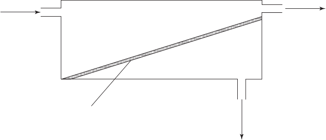
FIGURE 9-1
S chematic of separation process through reverse osmosis or nanofiltration membrane.
Feed stream
Feed-concentrate channel
Permeate channel
Semipermeable
membrane
Waste stream containing
impermeable components
(concentrate or reject)
Product stream containing
permeable components
(permeate)
REVERSE OSMOSIS AND NANOFILTRATION 9-3
9 -2 THEORY
Osmosis
Osmosis i s defined as the spontaneous transport of a solvent (in this case, water) from a dilute solu-
tion to a concentrated solution across an ideal semipermeable membrane that impedes passage of
the solute (ions in solution) but allows the solvent (water) to flow. This is shown schematically in
Figure 9-3 . The syste
m will reach equilibrium when the hydrostatic pressure on the saline water side
balances the force moving the water through the membrane. This is noted as the osmotic pressure
in Figure 9-3 b. If pressure is exerted to overcome the osmotic pressure, the solvent (pure water) will
flow from the saline side to the fresh water side. The semipermeable m
embrane will not allow the
passage of molecules other than water and gases. This is noted as reverse osmosis in Figure 9-3 c.
Osmotic Pressure
The driving force for diffusion is typically described as a concentration gradient. A more rigorous
explanation is a gradient in Gibbs energy. The general form of the Gibbs function is
GPSTun
i
i
∂∂∂∂
V
(9-1)
where G Gibbs energy, J
vo
l
u
m
e
m
,
3
V
P pressure, Pa
S entropy, J/K
T absolute temperature, K
u
i
chemical potential of solute i, J/mole
n
i
amount of solute i in solution, moles
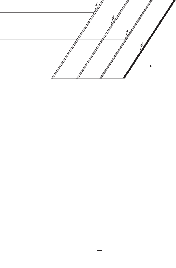
FIGURE 9-2
Common constituents removed by membrane processes.
MF microfiltration;
UF ultrafiltration;
NF nanofiltration;
RO reverse osmosis.
Bacteria,
protozoa, algae,
particies 0.1 m
Viruses and small colloids
Dissolved organic matter
and divalent ions (Ca
2
; Mg
2
)
Monovalent species (Na
; Cl
)
Water
Pore
sizes
Nonporous
Con
c
e
ntrat
e
Con
c
e
ntrat
e
Con
c
e
ntrat
e
Con
c
e
ntrat
e
MF UF NF RO
0.1 m 0.01 m 0.001 m
9-4 WATER AND WASTEWATER ENGINEERING
Chemical potential is defined as the change in Gibbs energy resulting from a change in the
amount of component i when the temperature and pressure are held constant
u
G
i
n
i
(9-2)
Thus, under constant temperature conditions, equilibrium ( G 0) will be achieved when
Pun
ii
V
(9-3)
The pressure ( P ) to balance the difference in chemical potential of a solute is called the osmotic
pressure (MWH, 2005). By convention it is given the symbol . The equation for osmotic pres-
sure can be derived thermodynamically using assumptions of incompressible and ideal solution
behavior:
iCRT
(9-4)
where i number of ions produced during dissociation of solute
osmoticcoefficient un itless,
C concentration of all solutes, moles/L
R universal gas constant, 8.314 kPa · m
3
/kg mole · K
T absolute temperature, K
The number of ions per mole, i, for example would be 2 for NaCl. The osmotic coefficient, ,
depends on the nature of the substance and its concentration. For NaCl it ranges from 0.93 to
1.03 over a concentration range of 10 to 120 g/L of salt. Seawater has an osmotic coefficient that
varies
from 0.85 to 0.95 for the same concentration range. Robinson and Stokes (1959) provide
osmotic coefficients for a variety of electrolytes.
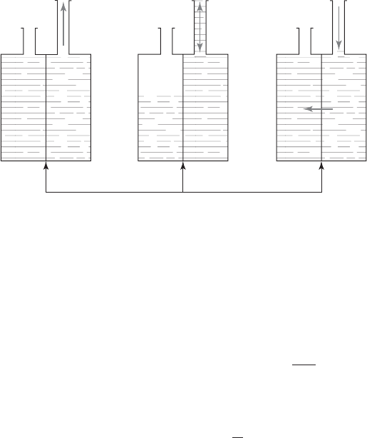
FIGURE 9-3
Direct and reverse osmosis. ( Source: Davis and Cornwell, 2008.)
Semipermeable
membrane
Fresh
water
Low
TDS
Saline
water
High
TDS
Low
TDS
High
TDS
Osmosis
(a)(b)(c)
Osmotic
equilibrium
Osmotic
pressure
Reverse
osmosis
Osmotic
pressure
WaterWater

REVERSE OSMOSIS AND NANOFILTRATION 9-5
Flux
Several models have been developed to describe the flux of water (m
3
/ d · m
2
of membrane sur-
face area) and solutes (kg/m
2
· d) through the RO membrane. Because there is some controversy
about the mechanics of permeation, thes e are presented in summary here. For more details see
MWH (2005). The models are:
• Solution-diffusion model: Permeation occurs through a dense membrane where the active
layer is permeable but nonporous. Water and
solutes dissolve into the solid membrane mate-
rial, diffuse through the solid, and reliquefy on the permeate side of the membrane. Separa-
tion occurs when the flux of the water is different from the flux of the solutes.
• Pore flow model: This model assumes the RO membranes have void spaces (pores) through
which the liquid water travels. It considers the water and solute fluxes to be coupled. Rejec-
tion occurs because the solute molecules are “strained” at the entrance to the pores. Because
the solute and water molecules are similar in size, the rejection mechanism i
s not a physical
sieving but rather a chemical effect such as electrostatic repulsion.
• Preferential sorption-capillary flow model: This model assumes the membrane has pores.
Separation occurs when one component of the feed solution (either solute or water) is pref-
erentially adsorbed on the pore walls and is transported through the me
mbrane by surface
diffusion.
Ultimately, these models express flux as the product of a mass transfer coefficient and a driv-
ing force. The water flux is
J
kP
ww
()
(9-5)
where J
w
volumetric flux of water, m
3
/ d · m
2
k
w
mass transfer coefficient for water flux, m
3
/ d · m
2
· kPa
P net transmembrane pressure, kPa
difference in osmotic pressure between the feed and the permeate, kPa
The driving force for the solute flux is the concentration gradient. The solute flux is
J
k C
ss
()
(9-6)
where J
s
mass flux of solute, kg/d · m
2
k
s
mass transfer coefficient for solute flux, m
3
/ d · m
2
C concentration gradient across the membrane, kg/m
3
The flux of solutes through the membrane is
JCJ
spw
(9-7)
where C
p
solute concentration in the permeate, kg/m
3
.
The recovery ( r ) is the ratio of permeate flow to feed water flow:
r
Q
Q
P
F
(9-8)

9-6 WATER AND WASTEWATER ENGINEERING
The flow balance and mass balance are
QQQ
FPC
(9-9)
CQ CQ CQ
FF PP CC
(9-10)
where the subscripts refer to feed water ( F ), permeate ( P ), and concentrate ( C ).
Rejection is defined as
Rej
C
C
P
F
1
(9-11)
With an assumption that the rejection is close to 100 percent, these equations can be solved for
the concentrate concentration:
CC
r
CF
1
⎛
⎝
⎜
⎞
⎠
⎟
(9-12)
9-3 PROPERTIES OF RO AND NF MEMBRANES
Membrane Material
The materials most widely used in RO and NF are cellulosic derivatives and polyamide derivatives.
Cellulosic acetate (CA), the common commercial material, is not tolerant to temperatures
above 30 C and tends to hydrolyze when the pH is less than 3 or greater than 8. It is susceptible to
biologi
cal degradation and degrades with free chlorine concentrations above 1 mg/L. Most mem-
brane manufacturers guarantee integrity of membranes if the chlorine concentration and contact
time are within specified limits.
Polyamide (PA) membranes are generally resistant to biological degradation, are
stable over
a pH range of 3 to 11, and do not hydrolyze in water. Under similar pressure and temperature
conditions, PA membranes can produce higher water flux and higher salt rejection than CA mem-
branes. However, PA membranes are more susceptible to fouling and cannot tolerate free chlo-
rine at any concentration (MWH, 2005).
Membrane Configuration
The membrane units are fabricated in either a spiral-wound configuration or a hollow-fiber con-
figuration.
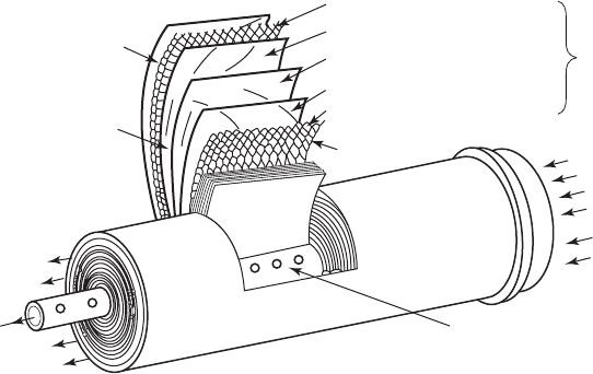
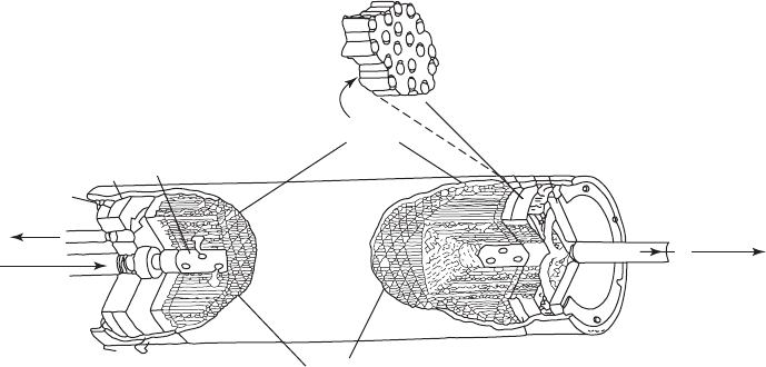
The spiral-wound configuration is shown in Figu re 9-4 . Two sheets of flat-sheet membrane
are joined along three sides with the active membrane layer facing ou t. A spacer is placed be-
tween the membrane sheets to keep them from to
uching. The open end of the envelope formed by
the two sheets is attached to a perforated central tube that collects the permeate. The spiral-wound
elements are typically 1 m long and 0.3 m in diameter. The area for a 1 m long element would be
about 30 m
2
. Individual elements have a permeate recovery of 5 to 15 percent. To achieve higher
recoveries, elements are placed in series. Typically, four to seven elements are arranged in series
in a pressure vessel (MWH, 2005).
REVERSE OSMOSIS AND NANOFILTRATION 9-7
The hollow-fiber element has several hundred thousand fibers with outside diameters on the
order of 0.085 mm suspended in a pressure vessel as shown in Figure 9-5 . Permeate recovery is
about 30 percent for each element.
The spiral-wound configuration is the most co
mmon for the production of drinking water
from grou ndwater and surface water. The hollow-fiber configuration is used extensively for
desalinization of seawater in the Middle Eas t (Taylor and Wiesner, 1999).
Temperature Effects
Temperature affects water viscosity and the membrane material. In general, the permeate flow
increases as the temperature rises and the viscosity decreases. The relationship between membrane
material, temperature, and flux is specific to individual products. Correction factors sho
uld be
obtained from manufacturers (AWWA, 1999).
Service Life
Membrane fouling generally occurs by one of the following mechanisms (AWWA, 1999):
• Deposition of silt or other suspended solids.
• Inorganic scale deposits.
• Biological fouling.
• Interaction of organic constituents with the membrane.
O xidation of the membrane from chlorination prior to ion exchange will significantly reduce
the s
ervice life. This is especially true for PA membranes. If prechlorination is essential, CA res-
ins are recommended (MWH, 2005).
Source water
Membrane (cast on fabric backing)
Membrane (cast on fabric backing)
Source water & flow spacer
Source water &
flow spacer
Concentrate
Concentrate
Cutaway view of a spiral membrane module
Permeate
water
Processed water passes
through the membranes
on both sides of the porous
permeate carrier.
The
permeate flows through the
porous material in a spiral path
until it contacts and flows through
the holes in the permeate core tube.
Source
water
Source water
Membrane leaf
Adapted from Hydranautics
Water Systems diagram
Porous permeate carrier
FIGURE 9-4
T ypical spiral-wound RO membrane element.
( Source: U.S. AID, 1980.)
9-8 WATER AND WASTEWATER ENGINEERING
E xcessive concentrations of iron and manganese, if oxidized, will form precipitates that will
foul the membrane. Scaling will also occur as a result of increasing recovery because the concen-
tration of limiting salts will increase to their solubility limit, and they will precipitate. The most
common scales of limiting
salts are calcium carbonate and calcium sulfate. Others of concern
are calcium fluoride, calcium orthophosphate, strontium sulfate, barium sulfate, and amorphous
silica (MWH, 2005).
An additional negative impact is the result of the accumulation of solutes
that form a bound-
ary layer of high concentration at the membrane surface. The concentration at the surface of the
membrane becomes higher than the concentration in the bulk feed water. This effect is called
polarization. It has the following negative impacts (MWH, 2005):
• Water flux is lower because the osmotic pressure gradient is higher.
• Rejection is
lower.
• Solubility limits of solutes are exceeded leading to precipitation and scaling.
These issues may be ameliorated by pretreatment of the raw water and operational procedures.
9-4 RO AND NF PRACTICE
Process Description
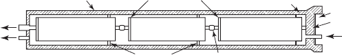
The smallest physical unit of production capacity is the membrane element. The membrane
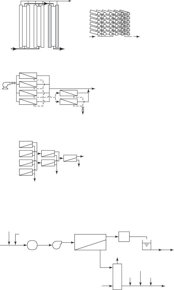
elements are enclosed in pressure vessels as shown in Figure 9-6 . A group of pressure vessels
operating in parallel is called a stage. The arrangement of one or more stages is called an array.
In a multistage process
the stages are arranged in series. The number of pressure vessels
decreases in each succeeding stage to maintain the water velocity in the feed channel as permeate is
Hollow
fibers
Feed
tube
Flow
screen
Concentrate
Pretreated
source
water
Permeate
Permeate
FIGURE 9-5
T ypical hollow fiber NF/RO membrane module.
(Adapted from U.S. AID, 1980.)
REVERSE OSMOSIS AND NANOFILTRATION 9-9
extracted. A two-stage arrangement is shown in Figure 9-7 a and schematically in Figure 9-7 b. A
three-stage arrangement is shown schematically in Figure 9-7 c.
A schematic of a typical RO or NF facility is shown in Figure 9-8 .
Pretreatment
The first pretreatment is to prevent scaling by silica (SiO
2
) and sparingly soluble salts such as
calcium carbonate and calcium sulfate. Scale control consists of pH adjustment and/or addition of
an antiscalant. Typically, the antiscalants are proprietary polymeric compounds.
Unlike ion exc hange column
s, RO/NF systems are not backwashed. Therefore, the second
pretreatment process is filtration to remove particulate matter that will clog the feed channels or
accumulate on the membrane surface. For surface water sources granular filtration or membrane
filtration may be required. The minimum filtration requirement regardle
ss of the water source is
a cartridge filter rated in the 1 to 25 m range with a typical rating of 5 m. The maximum feed
water turbidity recommended by manufacturers is 1 NTU with a preferred turbidity of less than
0.2 NTU (Bergman, 2005).
Disinfection may also be required to prevent biologic
al fouling. Even though groundwater
is expected to have a very low microbial population, when the membrane is out of service, the
population on the membrane can quickly multiply. Chlorine solutions may be used for CA mem-
branes, but other techniques such as ultraviolet irradiation, or chlorination followed
by dechlori-
nation are used for PA membranes.
Post-treatment
Because the RO/NF membranes do not remove gases, these are stripped after the RO/NF unit.
The primary gases of concern are hydrogen sulfide and carbon dioxide. The removal of H
2
S is to
prevent odor complaints. CO
2
is removed because it forms carbonic acid.
The permeate has a low pH as a result of removal of alkalinity (buffering capacity) from
the water and the addition of acid to prevent scaling. This water is corrosive to the d istribution
system. In addition to stripping CO
2
, addition of a base and corrosion inhibitor is generally re-
quired. Split treatment and blending may aid in corrosion control. Maximum Contaminant Limits
(MCLs) for constituents such as arsenic must be considered if split treatment is part of the corro-
sion control strategy.
Concentrate Stream
The concentrate stream is under high pressure as it leaves the RO/NF unit. Energy recovery sys-
tems are often used in reducing the pressure.
Permeate
water
Pressure vessel
Brine seals O-ring
connector
Snap ring
End cap
Source water inle
t
Anti-telescoping
support
Concentrate (brine)
seal
Membrane
element
module
Membrane
element
module
Membrane
element
module
Concentrate
outlet
FIGURE 9-6
Cross section of pressure vessel with three spiral-wound RO elements.
( Source: U.S. AID, 1980.)
9-10 WATER AND WASTEWATER ENGINEERING
Plan view
(a)
(b)
(c)
End-perspective view
Permeate
(product)
Concentrate
(reject)
(brine)
Concentrate
Permeate
Permeate
Permeate
ConcentrateFeed
Stage 2:
12 Vessels
72 Elements
Permeate
Concentrate
Feed
Stage 1:
24 Vessels
144 Elements
FIGURE 9-7
E xample array arrangements: (a) a 4 2 stage arrangem ent showing 12 pres-
sure vessels, each with 6 elements per vessel; ( b ) a schematic of a 4 2 array;
( c ) a schematic of a 4 2 1 array.
Raw water
Acid
Antiscalant
Prefiltration
Feed
pumps
Membrane
arrays
Energy
recovery
Break tank
Concentrate
disposal
Corrosion
inhibitor
DisinfectantBase
Air
Treated water
to distribution
system
CO
2
stripping
tower
CO
2
FIGURE 9-8
S chematic of typical reverse osmosis facility.