Water and Wastewater Engineering
Подождите немного. Документ загружается.

8-10 WATER AND WASTEWATER ENGINEERING
potential of causing physical damage to the resin beads, the hydraulic requirements of the resin
rather than the kinetics for ion exchange govern the selection of the resin particle size.
Ion exchange resin beads are spherical. They are produced in particle diameters ranging from
0.04 to 1.0 mm. In the United States, the particle sizes are sold by standar
d sieve screen or “mesh”
sizes. A table of U.S. Standard Screen sizes and their equivalent diameters is given in Appendix B.
The common sieve size ranges used are 16 to 50 and 50 to 100. The smaller number is the largest
diameter sieve, and the larger number is the smallest diameter sieve. The manufactu
rer’s specifi-
cation is generally given the notation 16 50 or 50 100. Thus, for a 16 50 resin, all of the
resin beads will pass the number 16 sieve, and none will pass the number 50 sieve.
Other data provided by the manufacturer includes the effective size ( d
10
) and the uniformi ty
coefficient. The effective size is the mesh size that passes 10 percent of a sieved sample. The
uniformity coefficient is the ratio of the d
60
to the d
10
resin sizes. These data are provided to
facilitate hydraulic design.
Structural Stability and Service Life. As noted above, high pressure drops through the bed
have the potential to cause resin bead compression. This, in turn, can cause inadequate liquid
distribution and reduced flow. In addition the resin beads are al
so susceptible to swelling, shrink-
ing, and abrasion from excessive backwashing. These effects reduce the structural integrity of the
resin and shorten its operating life.
O xidation of the resin beads, especially strong acid sulfonated polystyrene-DVB resins, from
chlorination prior to ion exchange will significantly re
duce service life. If prechlorination is essential,
resins with high cross-linking are recommended (MWH, 2005).
E xcessive concentrations of iron and manganese, if oxidized, will form precipitates that will
foul the resin. GLUMRB (2003) specifies that iron, manganese, or a combination of the two
should not exceed 0.3 mg/L in the water applied to the re
sin. Organic compounds may foul the
resin by irreversibly binding to strong base anion exchange resins.
T urbidity should not exceed 5 NTU in water applied to cation exchange softeners (GLUMRB,
2003).
Some of these issues are remedied with the selection of an appropriate resin and proper
arrangement of the
sequence of pretreatment processes.
8-3 PROCESS OPERATION
To contact the water with the ion exchange resin, it is passed through a columnar pressure vessel
as shown in Figure 8-3 . The water is passed through the colu mn until the effluent no longer
meets the treatment objective. The column is then regenerated. The two common methods for
regeneration (cocurrent and countercurrent) are used to i
dentify the operating schemes.
Cocurrent Operation
In this scheme the regeneration step is conducted in the same flow direction as the treatment
flow. The direction of both flows is usually downward. For softening operations where some
leakage of hardness in the effluent can be tolerated, this operational scheme is frequently chosen.
It is usually the lowest cos
t design and the simplest to operate. The domestic water softener is a
familiar example of this type of design (Brown, 1998).
ION EXCHANGE 8-11
The following steps are used in the ion exchange cycle :
• Service. The raw water is passed downward through the column until the hard-
ness exiting the column exceeds the design limits. The column is taken
out of service and another column is brought on line.
• Backwash. A flow of water is introduced thro
ugh the underdrain. It flows up through
the bed sufficient to expand the bed by 50 percent. The purpose is to
relieve hydraulic compaction (Gottlieb, 2005), and to move the finer
resin material and fragments to the top of the column and remove any
suspended solids that have accumulated d
uring the service cycle.
• Regeneration. The regenerating chemical, for example, sodium chloride, flows downward
through the bed at a slow rate to allow the reactions to proceed toward com-
plete regeneration.
• Slow rinse. Rinse water is passed through the column at the same flow rate as
the regenerating flow rate to pu sh the regenerating chemical through
the bed.
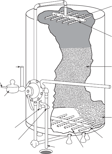
Upper manifold
Nozzles
Resin
Graded quartz
Lower manifold
Strainer nozzles
Backwash
outlet
Sight glass
Backwash controller
Meter
Water inlet
Water outlet
Regenerant
FIGURE 8-3
T ypical ion exchange resin column.
( Source: U.S. EPA, 1981.)
8-12 WATER AND WASTEWATER ENGINEERING
• Fast rinse. This is a final rinse step. The fast rinse flows at the same flow rate as the
service flow rate to remove any remaining regenerating solution.
• Return to service. The column is put back in use.
Countercurrent Operation
In this mode of operation the regenerant is passed though the resin in the opposite d irection to
that of the water being treated. Generally, the mode of operation is raw water flowing downward
and regenerant flow upward. In most cases, countercurrent operation will result in lower leak-
age and higher chemical efficiency than cocurrent operation. However, countercurrent opera-
tion is a more expens ive de
sign and is more com plicated to operate. Countercurrent operation is
used where (1) high purity water is required, (2) chem ical consumption must be minimized, or
(3) waste volu me must be minimized .
Bypass
A s noted previously, there will be some leakage of hardness through the column because the
passage of the saturation wave through the column is spread out, as shown in Figure 8-2 , and
because the high concentration of regenerant being released from the upper levels of the column
will “regenerate” lower portions of the column where polyvalent ions were not co
mpletely removed
in the regeneration cycle. The amount of leakage is usually less then 5 mg/L as CaCO
3
(Clifford,
1999). Thus, the treated water is softened far more than is necessary for normal consumer use.
Thus, passing the entire flow to satisfy demand through the column results in a larger column than
is necessary as well as consuming larger amounts of regeneration chemic
als. In addition, very soft
water is often corrosive.
To improve the stability of the water and make it less corrosive while reducing costs, a por-
tion of the flow is bypassed around the column and blended with the treated water to achieve the
design hardness. The bypass flow is calculated by solving the mass balanc
e for hardness at the
point where blending takes place. The mass balance of hardness is
QC QC Q C
treated treated bypass bypass blended bl
eended
(8-17)
and the flow balance is
QQQ
treated bypass blended
(8-18)
where Q
treated
flow rate of raw water entering column for treatment, m
3
/ d
Q
bypass
flow rate of water that is not treated, m
3
/ d
Q
blended
total design flow rate
C
treated
concentration of hardness in the treated water, mg/L as CaCO
3
C
bypass
hardness of the raw water, mg/L as CaCO
3
C
blended
design final hardness, mg/L as CaCO
3
The bypass flow rate is determined by simultaneous solution of these two equations.
ION EXCHANGE 8-13
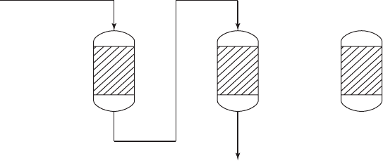
Multiple Columns
With the exception of home water softeners that may be shut down for a short period at night or that
may be replaced by a service technician, the exhausted column that is taken out of service must be
replaced by bringing another column on line. Although there are many alternate arrangements, three
schemes are more common than others
. They are (1) a standby column, (2) columns in series (known
in the trade as the “merry-go-round” system), and (3) columns in parallel (the “carousel” system).
In the standby system there is a minimum of two columns. One is in service while the other
is being regenerated and pla
ced in standby. The operating time of each column must be long
enough to allow for regeneration of the out-of-service column. This system does not provide any
redundancy if only two columns are provided. A three column arrangement provides one extra
column in the rotation and allows for backup during
maintenance.
A s show in Figure 8-4 , the first column in the merry-go-round system serves as a roughing
column and a second column serves as a polishing step.
In the carousel system, three columns are run in parallel while one is out of service. The three
column
s are in various stages of exhaustion: u p to and including breakthrough, less than break-
through, and substantially less than breakthrough. The water from the three columns is blended
to achieve a consistent product water. This system is more likely to be used to meet an MCL
requirement for a toxic con
stituent than for softening.
8-4 ION EXCHANGE PRACTICE
T ypical design criteria for cation and anion exchange systems are summarized in Table 8-2 . The
following paragraphs elaborate on the design parameters.
Resin Selection
There are several hundred different res ins available from United States and European manu-
facturers. Of these, the resins based on the polystyrene-DVB matrix are most widely used. The
operating capacity ( meq/mL as CaCO
3
) serves as the primary selection criterion. This differs
Column 1 Column 2 Column 3
FIGURE 8-4
Two columns in series with one column as standby. After exhaustion of column 1, it will be taken out of service and regener-
ated. Column 2 will become “lead” and column 3 will follow in series. When column 2 is exhausted, it is taken out of service
and column 3 bec
omes “lead.” Its effluent is passed through the regenerated column 1. This system has been called a “merry-
go-round” system.

8-14 WATER AND WASTEWATER ENGINEERING
from the exchange capacity in that it is a measure of the actual performance of the resin under
a defined set of conditions such as the raw water composition, empty-bed contact time (EBCT)
or service flow rate (SFR), and degree of regeneration. The operating capacity is always less
than the advertised exchange capacity be
cause of incomplete regeneration, early leakage (break-
through) that causes termination of the operational cycle to meet design limits, and efficiency of
regeneration (measured as eq NaCl/eq CaCO
3
).
S m all laboratory columns (1.0 to 5.0 cm inside diameter) have been effective in analyzing
alternative resins. Thes e columns can be scaled directly to full scale design if the loading rate
and EBCT are the same. Because the resin beads are small compared to the column diameter,
the error du
e to channeling of the water down the walls is small. The hydraulics of full scale
operation cannot be modeled by these small scale columns (MWH, 2005).
Strong acid Strong base
Parameter cation resin anion resin Unit
Exchange capacity 3.6–5.5 1.8–2.0 meq/g as CaCO
3
1.6–2.2 0.8–1.4 meq/mL as CaCO
3
Operating capacity
a
50–70 40–60 % of exchange capacity
Moisture content 40–80 35–80 %
Shipping weight (moist) 640–930 670–720 kg/m
3
Screen size 16 50 16 50
Service flow rate 200–2000 200–2000 m
3
/d · m
3
of resin
8–40 8–40 BV/h
Surface loading rate 400–800 400–800 m
3
/d · m
2
or m/d
Backwash rate 12–20 5–7.5 m
3
/h · m
2
or m/h
Backwash duration 5–155–20 min
Bed expansion 50 50–75 %
Regenerant NaCl NaCl
Regenerant concentration 5–10 2–15 %
Regenerant dose 80–320 80–320 kg NaCl/m
3
of resin
Regeneration flow rate 60–120 60–120 m
3
/d · m
2
or m/d
2–5 2–5 BV/h
Rinse volume2–5 2–10 BV
pH range 0–14 0–14 units
Max. operating temp. 140 OH
form 60; C
C
form 100
Turbidity limit 55 NTU
Iron limit 5 0.1 mg/L as Fe
Total Fe Mn 0.3 0.3 mg/L
Chlorine limit 1.0 0.1 mg/L of Cl
2
a
Operating capacity depends on the method of regeneration and amount of regenerant applied.
Sources: Clifford, 1999; GLUMRB, 2003; MWH, 2005.
TABLE 8-2
Typical ranges for design data and criteria for strong acid cation and strong base anion resins
ION EXCHANGE 8-15
The larger the laboratory or pilot scale column, the better will be the results from scale-up.
Although 60 cm long, 1 to 5 cm diameter columns are adequate for laboratory studies, larger
diameter columns (for example, 10 cm) that have res in bed depths greater than 1 m are recom-
mended (Reynolds and Richards, 1996; MWH, 200
5).
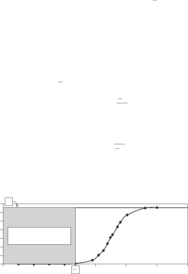
Breakthrough curves are obtained from laboratory scale or pilot scale data such as that shown
in Figure 8-5 . The design breakthrough concentration, shown as
b
V
in Figure 8-5 , may be used to
estimate the capacity of the resin by calculating the area between the influent concentration ( C
0
)
and the effluent concentration and dividing by the mass of resin in the column.
Flow Rates
The flow rate through the column affects the kinetics of the absorption bed. The longer the water
is in contact with the resin, the greater is the opportunity for the mechanisms of the exchange
process to come into play. Thus, the longer the contact time, the longer the time to reach break-
through. There are two parameters used to control the contact time: (1) empty-bed contact time
(EBCT) and (2) service flow rate (SFR) or exhausti
on rate. The EBCT is calculated as the vol-
ume occupied by the resin (
R
V
) divided by the flow rate:
EBCT
Q
R
V
(8-19)
The service flow rate is
SFR
Q
R
V
(8-20)
The EBCT and SFR are used for ease of calculation. An ac tual detention time in the bed
would have to account for the porosity. Typic al EBCTs range from 1.5 to 7.5 min and SFRs
range from 200 to 1,000 m
3
of water per day for each cubic meter of resin (m
3
/ d · m
3
). The SFR
0
1
2
3
4
5
6
7
012
b
C
0
3 4 5 6
Volume, m
3
C, meq/L as CaCO
3
Area 6.572 meq/L 2,350 L
15,444 meq
V
FIGURE 8-5
Ion exchange softening breakthrough curve.
8-16 WATER AND WASTEWATER ENGINEERING
may also be expressed as bed volumes of water per hour (BV/h). The usual range of values is 8 to
40 BV/h. EBCTs greater than 7.5 min and SFRs less than 200 m
3
/ d · m
3
are acceptable because
they provide greater time for the reactions. Shorter EBCTs and higher SFRs will result in earlier
breakthroughs.
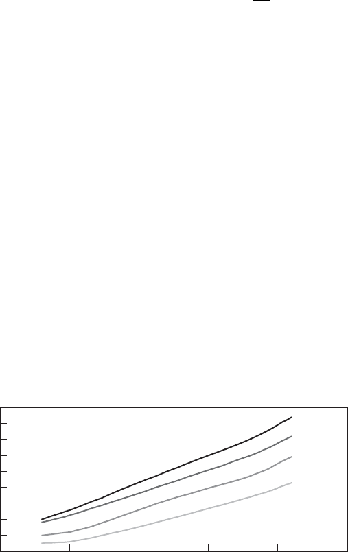
The surface loading rate (SLR) is limited to control the pressure drop across the bed and
thereby control breakage of the resin beads. It is expressed as
SLR
Q
A
c
(8-21)
where A
c
the cross-sectional area of the resin bed, m
2
.
In general, the maximum allowable pressure drop across the bed is about 140 kPa. Because
the pressure drop increases over time as the bed is operated, the design value for pressure drop
is usually about 35 to 70 kPa less than this . This results in a maximum SLR of about 880 cubic
meters per day per square meter of cross-sectional area (m
3
/ d · m
2
or m/d). SLRs range from 175
to 880 m/d (Gottlieb, 2005). GLUMRB (2003) specifies that the rate should not exceed 400 m/d.
Typical manufacturers’ design curves for pressure drop are shown in Figure 8-6 .
Backwashing
A s noted previously, cocurrent beds are backwashed to relieve com pression and remove parti-
culate matter (often called “fines”). The backwash rate for strong acid cation resins is in the range
12–20 m
3
/h · m
2
of bed surface area. The backwashing period is on the order of 5 to 15 minutes.
Bed expansion during backwash is typically assumed to be 50 percent, but some authors report ex-
pansions up to 100 percent of the operating depth (Reynolds and Richards, 1996; MWH, 2005).
Estimation of Resin Volume
There are several methods for estimating the required resin volume. The one that will be described
here depends on the results of column studies. Column studies on the raw water provide a better
estimate of the kinetic behavior of the resin to the actual constituents in the water than either
synthetic water data or equilibrium data provided by m
anufacturers.
0
10
20
30
40
50
60
70
80
90
0 200 400 600 800 1000
Surface loading rate, m
3
/d-m
2
Pressure drop, kPa/m of resin
5C
10C
20C
25C
FIGURE 8-6
T ypical ion exchange resin pressure drop curves at various water temperatures. Actual
manufacturer’s data should be used for design.

ION EXCHANGE 8-17
The column should be operated long enough to achieve complete saturation of the bed
through several cycles of service and regeneration. To determine the optimum SFR, the flow rate
must be varied during the saturation loading tests. The main goal in determining the optimum
SFR is to reduce the capital cost of the colum
n.
In the simplest expression, the resin volume required to treat a given flow rate of water is
Q
SFR
R
V
(8-22)
One method for estimating the resin mass is based on the principle of mass balance. It is
illustrated in the following example.
Example 8-2. As part of the preliminary design for a softening plant, a sodium-based ion ex-
change column is to be evaluated. For the evaluation of alternatives, estimate the mass of moist
resin required to soften the Hard Times water (Example 7-6) to a hardness of 80 mg/L as CaCO
3
.
The design flow rate is 275 m
3
/ d. Assume that there is no leakage from the column, that is,
C
treated
0.0 mg/L as CaCO
3
, that the moisture content of the resin is 44%, and the operat-
ing temperature is 10 C. Also assume that iron and turbidity c oncentrations are negligible. The
manufacturer’s resin operating capacity to breakthrough is 67% of the exchange capacity.
The laboratory scale column was 7.5 cm in diameter and the height of the resin in the col
umn
was 150.0 cm. The resin density on a moist basis is 0.85 g/cm
3
. The moisture content is the same
as the full scale column. The flow rate through the column was 0.18 m
3
/h.
Solution:
a . Begin by computing the meq of hardness removed per g of resin on a dry weight basis.
The mass of dry resin in the column is computed from the column dimensions, the unit
weight of the resin, and the moisture content of the resin.
()
()( )(
7 5
4
150085 1044
2
3
.
..
cm
cm g/cm
⎡
⎣
⎢
⎤
⎦
⎥
)) 3 154 35,.g
b. From the breakthrough curve of the laboratory column ( Figure 8-5 ) the meq of hardness
removed at breakthrough (
b
V
) was 15,444 meq.
c. The meq/g of dry resin is
15 444
3 154 35
489
,
,.
.
meq
g
meq/g
d. The total hardness of the Hard Times water is equal to the sum of the Ca
2
and Mg
2
or
238 mg/L as CaCO
3
90.6 mg/L as CaCO
3
328.6 mg/L as CaCO
3
.
e. A material balance on the flow downstream of the ion exchange column is used to deter-
mine the bypass flowrate.
8-18 WATER AND WASTEWATER ENGINEERING
QC QC Q C
treated treated bypass bypass blended bl
eended
With no leakage C
treated
0.0 mg/L and material balance equation is
QQ
treated bypass
mg/L as Ca() ( ) (0 328 6 2
3
.CO775 80
275
3
3
3
m /dmg/L as CaCO
m /
bypass
)( )
(
Q
ddmg/L as CaCO
mg/L as CaCO
)( )80
328 6
66
3
3
.
.. 9 5
3
m /d
f. The flow rate passing through the ion exchange column is
275 66 95 208 05
33 3
m /dm/dm/d..
g. The meq/L of hardness to be removed is
()328 6
1
50
6 572
3
..mg/L as CaCO
meq/mg
⎛
⎝
⎜
⎞
⎠
⎟
meq/L
where 50 meq/mg is the equivalent weight of CaCO
3
.
h. The meq of hardness to be removed in one day is
()()()()6 572 208 05 1 000 1
33
..,meq/L m /d L/md113710
6
. meq
i. The mass of dry resin required is
()()1 3710
1
489
10
6 3
.
.
meq
g
meq
kg g
⎛
⎝
⎜
⎞
⎠
⎟
/ 2279 61 280.or kg
j. The mass of resin on a moist basis is
()280
1
1044
500kg kg
.
⎛
⎝
⎞
⎠
k. To account for the manufacturer’s operating capacity to breakthrough, increase the
mount of resin to
1
067
500 746 27 750
.
.()kg or kg
Comments:
1 . The estimated resin was given in meq hardness/g of dry resin. This estimate could also be
made as meq of hardness/mL of moist resin. The resin is shipped and installed moist. The

ION EXCHANGE 8-19
volume should be estimated in the test column after the test column has been backwashed
and settled over several cycles.
2. The assumption of zero leakage is not realistic. As noted above, it will usually be some
concentration less than 5 mg/L as CaCO
3
.
3. The estimate of the hardness removed by the resin is determined by computing the area
under the breakthrough curve at the “design breakthrough.” F or a two column system
the design breakthrough is some hardness concentration above the leakage. For three
colum ns in series, the design breakthrough
may be as high as complete bed exhaus-
tion. Likewise, in the parallel system with four columns, exhaustion of the bed may be
selected as the design breakthrough.
Regeneration
Resins operated on the sodium cycle are usually regenerated with a 5 to 10% brine solution. The
mass loading ranges from 80 to 320 kg NaCl/m
3
of resin with 80 to 160 kg NaCl/m
3
of resin
being typical. The liquid flow rate is 60 to 120 m
3
/ d · m
2
of surface area or in terms of bed vol-
umes, about 2–5 BV/h (Reynolds and Richards, 1996; MWH, 2005).
Slow Rinse
The water rinse to push the regenerate through the bed is at the same flow rate as the regeneration.
Cycle Time
A minimum of two columns is recommended for redundancy: one in service and one in regenera-
tion or standby. One column in service with storage is an alternative, but it provides no redun-
dancy for mechanical or resin rehabilitation. Even with two columns, the out-of-service time must
be less than the operating tim
e for the in-service column to reach breakthrough. The following
may be used to estimate the out-of-service time (Clifford, 1999):
ttttt
os bw r srfr
(8-23)
where t
os
out-of-service time
t
bw
time for backwashing, 5 to 15 min
t
r
time for regeneration, 30 to 60 min
t
sr
time for slow rinse, 10 to 30 min
t
fr
time for fast rinse, 5 to 15 min
Using the maximum estimate for each of these steps, the total out-of-service time is about
two hours.
Example 8-3. An alternative three column design for Hard Times ( Example 8-2 ) is to be evalu-
ated. In this alternative, the columns will be in series and exha
ustion of the resin is the “design
breakthrough.” The total out-of-service time is estimated to be two hours.