Water and Wastewater Engineering
Подождите немного. Документ загружается.


3-24 WATER AND WASTEWATER ENGINEERING
The design must provide NPSH
A
NPSH
R
. Of the terms in Equations 3-7 and 3-8, the de-
signer can adjust the height of the water surface ( h
s
) and the friction losses ( h
fs
). Because of the
requirements for piping to the pump, h
s
i s generally the most easy to manipulate. Example 3-4
illustrates the calculations.
Example 3-4. A pump intake is located 0.5 m below the water surface in a wet well located at
an elevation of 1,500 m above sea level. The water temperature is 5
C. The pump intake friction
headlosses amount to 0.015 m. The selected pump requires a NPSH of 1.0 m. Does the design of
the wet well provide NPSH
R
?
Solution:
a . From Table 3-7 , find h
a
8.66 m of water at 1,500 m elevation.
b. From Table 3-8 , find h
va
0.0889 m of water at 5
C.
c. With h
s
0.5 m, the net positive suction head available is
NPSH or m
A
866 05 0015 0 889 8 256826... . . .
d. NPSH
A
is NPSH
R
. Therefore, this design is acceptable.
System Head Curves. The system head curve is the TDH curve formed over the range of de-
sign flow rates (that is, the minimum, average, maximum). The TDH will vary with the flow rate
and will be approximately proportional to the square of the flow through the system because of the
change in the velocity head term in Equation 3-3. In addition, the TDH will vary as the static
head
changes because of drawdown in the wet well and changes in the surface elevation of the lake or
Adapted from L. Haar, J. S. Gallagher, and G. S. Kell,
NBS/NRC Steam Tables, Hemisphere Publishing Corp.,
New York, 1984.
TABLE 3-8
Vapor pressure as a function of temperature
Vapor pressure
Temperature, C kPa m of water
0 0.611 0.0623
5 0.872 0.0889
10 1.228 0.1253
15 1.706 0.1740
20 2.339 0.2386
253.169 0.3232
30 4.246 0.4331
35 5.627 0.5740
40 7.381 0.7529
50 12.34 1.259
INTAKE STRUCTURES 3-25
river. Appropriate pumps and pump valve systems must be selected to operate in the range of the
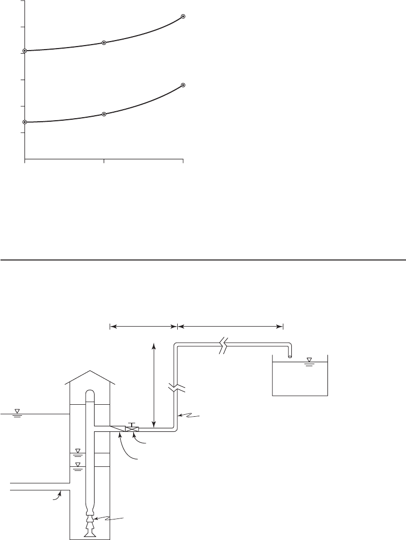
system head curve. Common practice is to plot two curves. One curve is plotted for the maximum
system total head and one for the minimum system total head as shown in Figure 3-16 .
Example 3-5. Develop the system head curves for the low-lift pump
station to the water treat-
ment plant pumping system shown in the sketch below. The minimum flow rate is 3,000 m
3
/ d.
The average flow rate is 6,000 m
3
/ d. The maximum flow rate is 12,000 m
3
/ d.
Minimum lake
elev.
Elev. 175.6 m
Pump
Check valve, swing, fully open
Gate valve, fully open
Note: all elbows = 90º,
flanged, long radius
400 mm Ø DIP
— Elev. = 190.9 m
12 m
2 m 286 m
Wet well
Conduit
Elev. 172.9 m
18
19
20
Flow rate, m
3
/d
Minimum
total head
Maximum
total head
3,000 6,000 12,000
Total dynamic head, m
17
16
15
FIGURE 3-16
S ystem total head curves.

3-26 WATER AND WASTEWATER ENGINEERING
Solution:
a. Calculate H
stat
for the maximum and minimum drawdown in the wet well.
Using the sketch elevations, the maximum static head is
H
stat
190 9 172 9 18 0...mmm
and the minimum static head is
H
stat
190 9 175 6153...mmm
b. Calculate the friction losses using Equation 3-5 for a 400 mm diameter ductile iron pipe
(DIP) at three flow rates.
From Appendix C, select C 100 for DIP. At the maximum flow rate of 12,000 m
3
/ d
or 0.139 m
3
/ s, for the 300 m long pipe the total friction headloss is
h
fd
10 7
0139
100
300
04
3
185
.
.
.
.
m /s m
m
⎛
⎝
⎜
⎞
⎠
⎟
()
4487
144
.
.
⎛
⎝
⎜
⎞
⎠
⎟
m
Similarly for the average and low flow rates
h
h
fd
fd
0 399 0 4
011
..
.
or m at average flow
mmat low flow
c. Compared to the values calculated in (a) and (b), the losses for valves and fittings are
negligible and are neglected here. Likewise, the velocity headloss ( v
2
/2 g ) is very small
and is neglected here.
d. The plotting points for the system curves for the maximum drawdown are
18 0 1 44 19 44 12 000
18 0
3
.. . ,
.
mm mat m /d Q
mmm mat m /d
m
0 4 18 4 6 000
18 0 0 11
3
.. ,
..
Q
mm at m /d18 11 3 000
3
.,Q
For the minimum drawdown the plotting points are
153 144 1674 12000
153
3
.. . ,
.
mm mat m /d+ Q
mmm mat m /d
m
+
+
04 15 7 6 000
153 011
3
.. ,
..
Q
mm at m /d15 4 3 000
3
.,Q
These points are plotted in Figure 3-16 .
Pump Selection. Multiple pumps and/or variable speed pumps are selected to cover the range
of conditions described by the system head curve. It is important to select a pump that will have
its best efficiency within the operating range of the system and preferably at the operating point
(head and dis
charge) where the pump will operate most often.
INTAKE STRUCTURES 3-27
P umps are selected from those commonly available from pump manufacturers. This then
becomes a problem of matching a pump characteristic or head-discharge curve from a pump
manufacturer’s catalog or database to the system head curve.
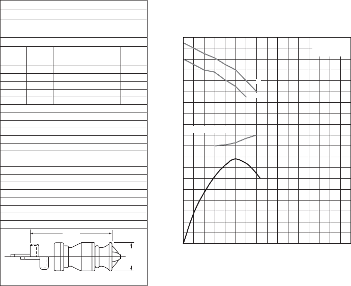
A typical, constant
speed, vertical turbine curve is shown in Figure 3-17 . Important features
of the curve to be noted are:
• The head delivered (ordinate) is per stage. Thus, for higher heads than noted, multiple
stages are identified in the selection of the pump.
• The maximum number of stages that may be used is specified
.
• The best efficiency point (BEP) is a function of the flow rate and the head.
• The required net positive suction head (NPSH
R
) may be specified per stage or as a total for
the maximum number of stages. Typically, it is only critical for the first stage.
• Multiple impeller sizes allow some adjustment over the range of capacity and head.
R a dial loads on the impeller and problems with cavitation are minimized when the pump i
s
operated at its BEP. Although it is not possible to operate at the BEP all the time, there is a range
of operating conditions that is preferred to optimize the life of the pump. The American National
0
1
2
20
0
80
60
40
1.0
2.0
3.0
4.0
100 200 300 400
Discharge, m
3
/h
NPSH required
at pump inlet, m
Efficiency, % Head per stage, m
NPSH required
Curve no. 3-18
Size 1 Rpm 1750
Single-stage lab head and horse-power with
enameled cast iron bowls and bronze impeller
Effieciency shown for 2 or more stages
No.
stages
Eff.
change
Eff.
change
Material
Eye area 32 cm
Thurst constang - A 2.3
Thurst constang - B 2.3
Thurst c
onstang - C 2.3
Max. no. std. stages 35
Max. operating pressure 3,900 kPa
Std. lateral 0.375
Std. shaft dia. 2.0 cm
Impeller number P-2397-10
Impeller wt. 25.0 kg
Bowl conn. - flanged
Add 37 cm per additional stage
Enclosed line shaft
Imp.-C.I.
Imp.-C.I. Enn
Bowl-C.I.
Bowl-Brz.
1
2
3
4
1
0
0
0
0
0
1
1
35 cm
72 cm
A
B
A
A 32 cm
B 31 cm
FIGURE 3-17
T ypical vertical head-discharge curve.

3-28 WATER AND WASTEWATER ENGINEERING
Standards Institute (ANSI) has provided the following guidance for the Preferred Operating
Range (POR) for vertical pumps (ANSI/HI 9.6.3-1997):
For specific speeds less than 87, the bounded region is between 70 and 120 perc ent of the
BEP flow rate.
For higher specific speeds, the bounded region is between 80 and 115 percent of the BEP
flow rate.
Specific speed is defined as
n
nQ
H
s
t
0 5
075
.
.
(3-9)
where n revolutions per minute
Q flow rate, m
3
/ s
H
t
total dynamic head, m
ANSI also establis hed a wider region than the POR called the Acceptable (or Allowable)
Operating Region (AOR). It “is that range of flow recommended by the pump manufacturer over
which the service life of a pump is not seriously compromis ed. Minimum bearing life will be
reduced and noise, vibration, and
component stresses will be increased when a pump is operated
outside its POR. As a result, service life within the AOR may be lower than within the POR.” The
pump may be operated in this region for short, infrequent periods without significant equipment
deterioration (Cooper and Tchobanoglous, 2006).
Example 3-6. Using the pump head-discharge curve shown in Fig
ure 3-17 for the system head
curve shown in Figure 3-16 , and data from Example 3-5, specify the following at the average
flow rate: (1) BEP, (2) number of stages, (3) efficiency at BEP, (4) the operating range of flow
rate, (5) motor power, (6) the depth of the wet well, and (7) the location of the pump intake.
Solution:
a . From Figure 3-16 , the maximum total system head is 18.4 m at the average flow rate
of 6,000 m
3
/ d. On Figure 3-17, the BEP is found at a flow rate of
6 000
24
250
3
3
, m /d
h/d
m /h
and a head of 3 m/stage.
b. The number of stages required is
No of stages
Total system head
Head per sta
.
gge
m
or
18 4
3
613 7
.
.
This is less than the maximum number of s tages allowed of 35 noted in the box in
Figure 3-17 .
c. From Figure 3-17 at 250 m
3
/h and 3 m head per stage, the efficiency is 78 percent for
impeller A.
d. From Figure 3-17 , the rpm 1,750. The flow rate is
250
3 600
0 0694
3
3
m /h
s/h
m /s
,
.
INTAKE STRUCTURES 3-29
e. From Figure 3-16 , the maximum TDH at 250 m
3
/h is 18.4 m.
The specific speed is
n
s
()( )
()
1750 0 0694
18 4
3 0 5
075
,.
.
rpmm/s
m
.
.
4461 0
888
5192
.
.
.
f. For specific speeds less than 87, the POR is from 70 to 120 percent of the BEP flow rate or
()( )070 250175
33
. m /h m /h
to
()( )12 250 300
33
. m /h m /h
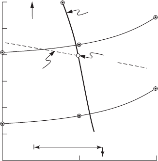
g. The pump curve is plotted on the system curve in Figure 3-18 .
h . Using Equation 3-3, the motor brake power is
P
()()()9 807 0 0694 18
078
15 7
33
..
.
.
kN/mm/s m
kW
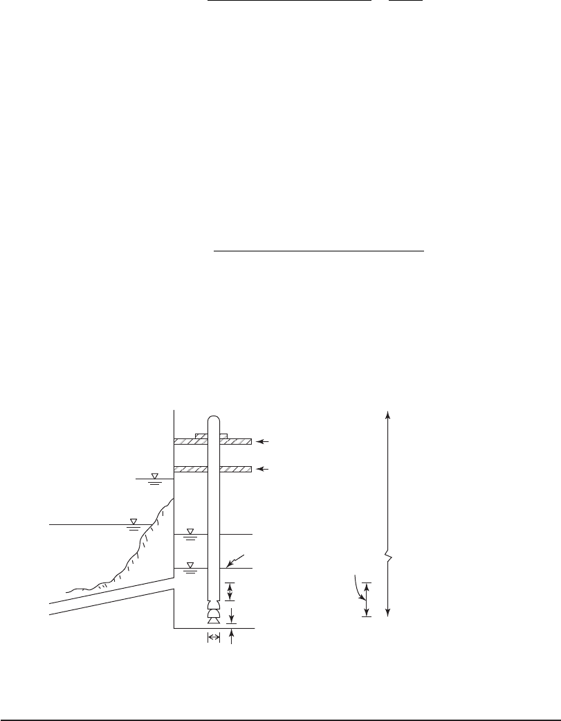
i. The depth of the wet well is determined by the hydraulics of the conduit, the depth of the
conduit carrying water to the wet well, and the minimum submergence required by
the pump. The following sketch shows the relationships using the results of calculations
in Example 3-3, the NPSH
R
for the selected pump, and the NPSH
A
a ssuming an altitude
of 500 m and a temperature of 5
C.
Maximum lake
elevation
Pump motor
Operating deck
Pump room floor
Elev. = 175.6 m
Maximum NPSH
R
= 1.6 m
NPSH
A
9.6 m
Minimum lake
surface evevation
Intake
conduit
Maximum drawdown
Elev. = 172.9
Minimum pump
submergence
0.5D
D
Comment. The selected pump is not “ideal” for the system curves. A pump with fewer stages
and a flatter head-discharge curve would be a better choice.
3-30 WATER AND WASTEWATER ENGINEERING
Infiltration Gallery or Ranney Wells
When the geological c onditions are favorable, an infiltration gallery or collector wells m ay be
placed onshore or offshore.
Direction. The infiltration gallery consists of perforated pipe laid parallel to the shore for
lakes. For rivers, the pipe gallery may be either at a right angle to the river flow or parallel to
shore depending on the groundwater flow pattern (Kawamura, 2000). As shown in Figure 3-6 ,
the Ranney well system will have well screens radiating from a
collector caisson.
Depth. The actual depth should be determined by hydrogeological studies that identify the pi-
ezometric surface and its variability. Common depths are generally in the range of 4 to 5 m below
the bottom of the river or lake.
Pipe Material. Because of the high potential for corrosion, perforated polyvinyl chloride
(PVC) or con
crete pipe is used for the collection gallery. Ranney well screens are generally made
of stainless steel.
Orifice Size. The diameter of each orifice is generally 1 to 2 cm. The number of orifices is 20
to 30 per square meter of the collector surface (Kawamura, 2000).
Length. The gallery must be long enough to meet the design capa
city. The velocity into each
orifice at the design capacity is limited to 0.03 m/s to minimize entrainment of sand.
Preferred
slope of
pump curve
Pump
curve
Maximum
total
head
Minimum
total
head
BEP
Lower
operating
point
POR
Upper operating poin
t
3,000
15
16
17
18
19
20
6,000
Flow rate, m
3
⁄d
12,000
Total dynamic head, m
∗
FIGURE 3-18
P ump and system curves.
INTAKE STRUCTURES 3-31
Slope. The gallery can be horizontal, but a slight slope of 500:1 will minimize air binding/
blockage (Kawamura, 2000).
Pipe Velocity. At design capacity, the velocity is limited to 1 m/s at the outlet of the gallery.
Backfilling. Because the Ranney well screens are bored into the natural aquifer material, there
is no backfilling required. The pipe laid in the gallery is backfilled with gravel and
sand similar
to that used in filter bed gradation (see Chapter 11 for details).
Junction Wells. At junction points in the gallery where the pipe changes direction and at the
end of the gallery, a well is provided. The recommended minimum diameter is 1 m (Kawamura,
2000).
Regulatory Considerations. In addition to the withdrawal restrictions that may be impos
ed,
the water removed from the infiltration gallery may be considered under the influence of the sur-
face water and thus subject to water quality regulations that apply to surface water. Nonetheless,
the filtering action of the ground improves the quality of the water and makes it easier to treat.
3-4 OPERATIONAL CONSIDERATIONS
Grit
Abrasive materials such as silt, sand, and shells is called grit. This material is very abrasive and
will result in excessive wear to mechanical equipment as well as potentially settling out during
low-demand flows.
When the source water bottom is soft and
subject to scour or when flood conditions result in
a high sediment load and turbidity, grit chambers are provided. The grit chamber is a horizontal
flow settling tank ( Figu re 3-19 ). The theoretical design basis of the grit chamber is Stokes’ law
which is discussed in Chapter 10.
The des
ign objective of the grit chamber is to remove sand or silt particles greater than 0.1 mm
in diameter. Generally, particles smaller than this do not pose a hazard to pumps and pipelines.
The design objectives for raw water grit chambers are significantly different from those used for
wastewater treatment. Thus, wastewater treatment plant design
s should not be used for raw water
grit removal. Typical design criteria are listed in Table 3-9 .
Ice
In cold regions, ice in its various forms is of concern. Surface ice and ice floes create struc-
tural hazards to exposed intakes. Selection of submerged intake alternatives alleviates this
problem.
Frazil ice i s small, disk-shaped ice crystals
(Foellmi, 2005). It has also been described as
slush. Frazil ice adheres to surfaces such as intake screens and pipe walls. The reduction in area
lowers the flow rate into the intake structure and ultimately will plug it. Frazil ice forms when
turbulent water is supercooled.

3-32 WATER AND WASTEWATER ENGINEERING
0.3 L
0.08 L
0.25 L
L
Diffuser
wall
Screen
0.1 L
D
Baffle
wall
Walkway
70°
Plan
Profile
FIGURE 3-19
Grit chamber.
Parameter Range of values
Location Downstream of the fine screen
and upstream of the raw water pumps
Number of chambers 2
Water depth
Mechanical grit removal 3 to 4 m
Manual grit removal 4 to 5 m
Length to width 4:1
Length to depth 6:1
Velocity 0.05 to 0.08 m/s
Detention time 6 to 15 min
Overflow rate
a
10 to 25 m/h.
TABLE 3-9
Water intake grit chamber design criteria
a
Overflow rate Q / surface area of water in tank.
A dapted from Kawamura, 2000.
E xperience on the Great Lakes and elsewhere indicates that location and design features of
submerged intakes can significantly reduce the buildup of frazil ice but probably cannot elimi-
nate it. Submerging intakes in deep water (10 m appears to be the minimum with 12 to 14 m
preferred) and sizing inlet ports for a maximum velocity of 10
cm/s minimizes frazil ice buildup.

INTAKE STRUCTURES 3-33
Heating the water at the intake port to 0.1
C also appears to work, but the energy requirements
are extremely large. Using smooth materials su ch as solid plastic and plastic-coated metal also
helps (Foellmi, 2005, Bosserrman et al., 2006). Wood is commonly used because of its low ther-
mal conductivit
y.
Anchor ice i s differentiated from frazil ice in that it forms in sheets and grows by attachment
of frazil ice. The methods of control are the same as those for frazil ice.
Zebra Mussels
The zebra mussel ( Dreissena polymorpha ) is a small bivalve mollusk that has alternating dark
and light bands on its shell and averages about 2.5 cm in length. The mussel grows filamentous
threads that allow it to attach to hard surfaces. Zebra mussels reproduce prolifically and as a con-
sequence clog intakes and pumps
. They are well established in the Great Lakes and are forecast
to infest all freshwater in two-thirds of the United States and all of southern Canada.
The control techniques currently in use are listed in Table 3-10 . In the Great Lakes area,
chlorine and potassium permanganate feed systems piped to the inlet port have been successful
in mitigating the problem. Intermittent chlorination is
used to kill the juveniles (velligers) before
shells develop and attachment becomes virtually permanent. This dosing scheme minimizes the
use of chlorine. Periodic cleaning of the screens is required to remove adult and dead mussels as
the chemical treatment d
oes not remove them. Care should be used in the application of chlorine
as the presence of naturally occurring organic matter may lead to the formation of trihalometh-
anes, a group of compounds that are regulated (see Chapter 2 for details).
Fish Protection
The need to provide a means to prevent fish from entering the intake structure is addressed by
one of three approaches:
• Physical barrier screens,
• Behavioral guidance systems, and
• Capture and release systems.
The highest standard of protection is for juvenile, endangered species. The National Oceani
c and
Atmospheric Administration (NOAA) has developed guidelines for inlets to protect these fish.
Treatment techniqueRemarks
Thermal 35C for 2 h
100% effective
Repeat 2 to 3 times per year
Chemical Oxidizing chemicals such as chlorine, potassium permanganate, and ozone
Continue for 2 or 3 weeks; continuous application may be required
Mechanical Shovel or scrape, high-pressure hose, sandbla
sting
Other Ultrasound, electrocution, oxygen depletion, UV light
TABLE 3-10
Zebra mussel control