Water and Wastewater Engineering
Подождите немного. Документ загружается.

3-14 WATER AND WASTEWATER ENGINEERING
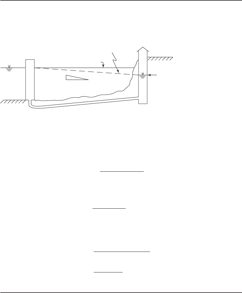
Example 3-3. Determine the diameter of a concrete conduit to transport the water from the
intake tower described Example 3-1 to a low-lift pump station on shore. From Table 3-3 , the
maximum flow rate is assumed to be 2.0( Q ), that is, twice the winter design flow rate. A sketch
of the minimum lake elevation and the maximum allowable drawdown in the low-lift pump sta-
tion is
shown below.
Maximum drawdown
Energy grade line
Minimum lake elevation
0.3 m / 100 m
Intake town
Low-lift pump station
Solution. From Example 3-1, the winter design flow rate is 6,000 m
3
/ d. The maximum flow rate is
2 0 2 6 000 12 000
33
., ,.() ( )Q m /dm/d
Solving Equation 3-2 for D:
D
Q
CS
()()()0 278
0 54
0 380
.
.
.
⎡
⎣
⎢
⎤
⎦
⎥
Convert Q to appropriate units:
Q
12 000
86 400
0139
3
3
,
,
.
m /d
s/d
m /s
Because of the very long life expectancy for the conduit, from Appendix C, select a very conser-
vative C 80 for concrete pipe. The slope in appropriate units is 0.3 m/100 m 0.003 m/m).
D
0139
0 278 80 0 003
3
0 54
0 3
.
..
.
m /s
()()()
.
⎡
⎣
⎢
⎤
⎦
⎥
880
3
0 380
0139
0 966
0 479 0
D
.
.
..
.
m /s
or
⎡
⎣
⎢
⎤
⎦
⎥
55500m or mm
Protection. When a pipeline is used, the pipe is laid in a trench at the bottom of the lake, reser-
voir, or river. The soil cover for the pipe is about 1 m over the top of the pipe with an additional
protective layer of crushed rock (Foellmi, 2005). Richardson (1969) suggests a rule of thumb is to
use 2.5 m
3
of rock per linear meter of pipe (2.5 m
3
/ m).

INTAKE STRUCTURES 3-15
Slope. To avoid air blockage, the conduit must be laid on a continuously rising or falling grade.
Shore Intake
Location. The minimum water depth for a shore intake should be about 2 m. For river intakes,
a stable channel is preferred. In general, the outside bank of an established river bend is preferred
over the inside bank because of low river velocities, shallow water, and the formation of sand
bars (Foellmi, 2005).
Intake Bay. The structu re should be d
ivided into two or more independent inlets to provide
redundancy. The inlet velocity may be as high as 0.5 m/s in warm climates but should be reduced
to 0.3 m/s or less if large am ounts of debris are expected (Kawamura, 2000). In cold climates,
inlet velocities below 0.10 m/s are used to minimize ice buildup (Foellmi, 2005).
Screens. Trash racks as described in Table 3-5 are used to remove large objects. An example is
shown in Figure 3-9 . Thes e are followed by fine screens to protect the pumps. Screenings from
the fine screen are collected in a roll-off box and disposed of in a municipal solid waste landfill.
The maximum head loss from clogging of the trash racks should be limited to between 0.75
and 1.5 m. The screen bars should be designed to withstand the differential hydraulic load.
A s shown in Figure 3-9 , a mechanical cleaning device is use
d to remove the debris from the
trash rack.
Wet Well
The wet well * should be divided into cells so that a portion can be taken out of service for inspec-
tion and maintenance of the equipment.
* The wet well is that portion of the low-lift pump station that serves as a reservoir of water in which the pump and screens are placed.
FIGURE 3-9
Coarse bar screen, mechanically cleaned.
( Source: Foellmi, 2005.)
3-16 WATER AND WASTEWATER ENGINEERING
Location. With the exception of the tower intake, the wet well is located at the s hore or river
bank. The decision whether or not to locate the wet well in a tower intake is dependent on the
distance between the tower and the shore. When the tower is close to shore, it may be more eco-
nomical to place the wet well in the tower rather than build two structures close together—one
for the intake and another for the wet well.
Dimensions. The area of the wet well must be large enough to accommodate the fine screen
and p
umps. Sufficient space must be provided to service or remove the mechanical equipment.
The overhead space above the operating deck must be sufficient to raise the equipment from the
wet well to the deck.
The d epth of the wet well is governed by hydraulic considerations. The high water level is
set at the highest elevation of the lake or reservoir or at the 500-
year flood level for rivers. The
bottom of the wet well must be low enough to allow drawdown of the wet well while pumping
at the design flow rate when the source water elevation is at its minimum level. In addition, there
must be enough depth to maintain the pump manufacturer’s required submergence to prevent
cavitation of the pump.
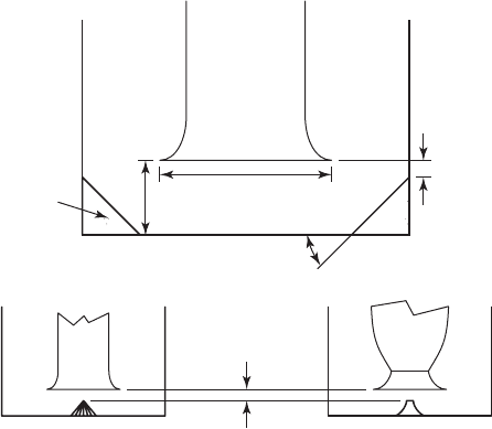
Vertical turbine pumps may be mounted in a can or barrel that ex
tends from the pump inlet
to near the bottom of the wet well. The entrance to the barrel is bell-shaped. Dimensions of wet
well appurtenances are given in terms of the bell diameter, D. To avoid interference between ad-
jacent intakes, they are spaced 2.5 D center-to-center with the additional provision of a minimum
distance between adjacent pumps of 1.2 m for access clearance. The bell is
set at 0.5 D above
the wet well floor ( Figure 3-10 ). The water velocity into the pump intake bell should be limited
to 1.1–1.2 m/s at runout, that is, the pump flow rate at the least possible dynamic head. In clean
water wet wells, cones are sometimes placed below the pump intake to prevent vortices. The top
of the cone is located 12 mm below the bell (Jones and Sanks, 2006).
Rec
tangular pump intake basins with multiple pumps are provided with dividing walls between
the pumps. The walls improve the flow patterns in the intake throat. The dividing walls should be
at a distance of at least 5.75 D apart from each other to be effective (Jones and Sanks, 2006).
0.125D
12 mm
clearance
Fillet
45
(b)
(a)
(c)
0.5D
D
FIGURE 3-10
P ump intake bell (a) and floor cones: right cone; ( b ),
(c) flat cone.
INTAKE STRUCTURES 3-17
Pump Criteria
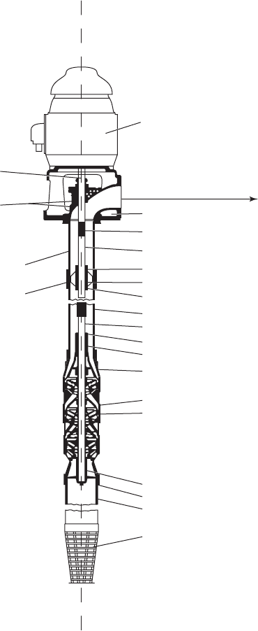
Pump Type. The most common pump used in the low-lift pump station is a vertical turbine pump
as shown in Figure 3-11 (Honeycutt and Clopton, 1976). The water enters the pump through the
strainer or screen. It is lifted by one or more impellers located inside the pump bowl ( Figure 3-12 ).
Pump motor
Top shaft
Prelubricating pipe
Top column pipe
Column pipe coupling
Discharge head
Discharge to wate
r
treatment plan
Shaft coupling
Line shaft
Bearing bracket
Shaft sleeve
Open lineshaft bearing
Column pipe
Impeller shaft
Bearing cap
Top bowl bearing
Top bowl
Bowl
Impeller
Suction head bearing
Suction head
Suction pipe
Strainer
FIGURE 3-11
Section of vertical turbine pump with clos ed impellers and open-line shafting (water
lubrication).
3-18 WATER AND WASTEWATER ENGINEERING
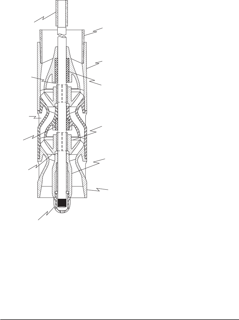
The water is discharged from the top impeller up through the column pipe to the discharge pipe.
Each impeller is designed to lift the water to a given height. This is the discharge head or pressure
delivered by the impeller. The flow rate of the pump is a function of its diameter and rotational
speed. For a given impeller design, higher discharge pressures are achieved by
adding impellers or
stages to the stack. There are, for example, three impellers shown in Figure 3-11 .
Pump Drive. Low-lift pumps are commonly driven by electric motors. These are mounted on the
operating deck. The range of demands (daily, weekly, seasonal) can be met with either multiple pumps
with constant speed drives or, in s
ome cases, with fewer pumps with variable speed drives. One
type of variable speed equipment that is frequently used is the adjustable frequency drive * ( A FD).
Shaft coupling
Impeller shaft
Column pipe
Upper discharge
vane
Upper discharge
vane bearing
Impeller bushing
Inlet vane
bearing
Inlet vane
Inlet vane
plu
g
Discharge vane
bearing
Impeller
Discharge vane
FIGURE 3-12
Section of bowls of a vertical turbine pump with open
impellers for a connection to open-line shafting.
* Practitioners and operators refer to this as a variable frequency drive or, more commonly, a VFD.

INTAKE STRUCTURES 3-19
The AFD allows changes in the flow rate by changing the frequency of the alternating current (AC)
electrical supply. The selection of the number of pumps and drive arrangement is based on an eco-
nomic evaluation of the alternatives that includes the capital investment for the pump(s) and the
drive(s) and the required operating floor area as well as the cost of power and
maintenance. The AFD
has a higher capital cost than constant speed drives but is often more efficient to operate because of
lower power costs that result from being able to match pumping rate to the demand for water.
The power input of the drive is estimated from the following equation:
P
QH
t
E
p
(3-3)
where P brake power, kW
specific weight of fluid, kN/m
3
9.807 kN/m
3
for water at 5
C
Q flow rate, m
3
/ s
H
t
total dynamic head, m
E
p
efficiency of pump
Pump Capacity. The flow rate of the pump is called the capacity or discharge ( Q ). The capac-
ity is usually expressed in cubic meters per second (m
3
/ s) for large pumps and cubic meters per
hour (m
3
/h) for small pumps.
Although the wet well structure is designed for anticipated dem ands at a design life of 50
to 75 years, common practice is to provide initial pumping capacity for a 20-year life. As the
demand increases over time, additional capacity may be add
ed as required by the addition or
replacement of pumping units (Honeycutt and Clopton, 1976).
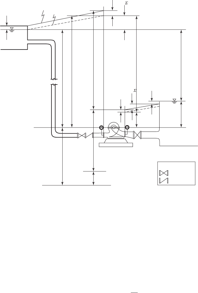
Head. The term head i s the elevation of a free surface of water above or below a reference datum.
The reference datum for a vertical flow centrifugal pump is the inlet to the impeller. Two cases are
illustrated in Figures 3-13 and 3-14 . The definition of terms u
sed in the figures is given in Table 3-6
on page 3-22.
The total energy required to deliver the water from the wet well to the discharge point at the
water treatment plant is commonly calculated in terms of equivalent elevation of a water column.
This is termed the total head or total dynamic head (H
t
or TDH). It is expressed in meters (m). It
is calculated as
TDH H hhh h h
v
g
stat ent fs fd f vs f vd
d
2
2
(3-4)
where, with the exception of h
ent
(which is the entrance loss), the terms are described in Table 3-6 .
The friction losses may be calculated from a revised form of the Hazen-Williams equation:
hh
Q
C
L
D
fs fd
or 10 7
185
487
.
.
.
⎛
⎝
⎞
⎠
⎛
⎝
⎜
⎞
⎠
⎟
(3-5)
where h
fs
or h
fd
head loss in m, L equivalent length of pipe in m, and the other terms are as
defined previously.
3-20 WATER AND WASTEWATER ENGINEERING
EGL
v
2
d
/2g
v
2
d
/2g
HGL
h
fd
h
fvd
h
fs
h
fvs
h
ent
h
gs
h
s
h
d
H
t
= TDH
Datum
NPSH
A
Key
Butterfly valve
Check valve
Absolute zero pressure
H
barometric
H
vapor
Gauge
Gauge
Pump
H
g
H
stat
h
gd
v
2
s
/2g
FIGURE 3-13
Terminology for a pump with a positive suction head.
Sanks (2006) offers several warnings in the use of this equation for estimating friction losses.
Errors of up to 40 percent may be encountered for pipes less than 200 mm in diameter and more
than 1,500 mm in diameter, for very cold or hot water, and for unusually high or low veloci-
ties. Growths of slime layers and corro
sion add to the inherent potential for errors in using the
Hazen-Williams equation or, for that matter, any equation for estimating friction losses. The
prudent engineer will use a range of coefficients to define a probable region of losses that may
be encountered.
The fitting and valve losses are estimated using Equation 3-6:
hhK
v
g
fvs fvd
or
2
2
(3-6)
where K energy loss coefficient. Energy loss coefficients are given in Appendix C.
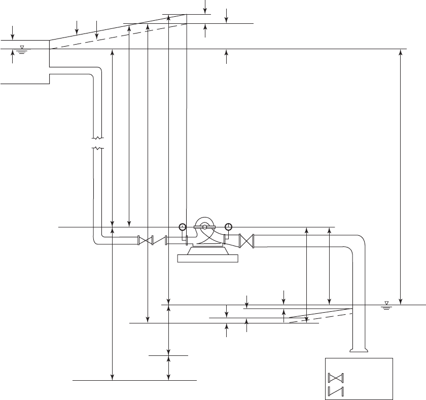
INTAKE STRUCTURES 3-21
Datum
H
baronetric
H
vapor
Gauge
Gauge
Pump
Key
Butterfly valve
Check valve
EGL
h
d
H
t
TDH
h
gd
H
g
HGL
Absolute zero pressure
NPSH
A
v
2
d
/2g
v
2
d
/2g
v
2
d
/2g
h
ent
h
gs
h
s
H
stat
h
fd
⌺h
fvd
h
fs
⌺h
fvs
FIGURE 3-14
Terminology for a pump with a negative suction head.
Net Positive Suction Head. Liquids at temperatures above their freezing point have a corre-
sponding vapor pressure. If the pressure in a pump suction pipe is reduced below the vapor pres-
sure, the liquid will flash, that is, it will form a vapor. Because no water pump of ordinary design
can pump only vapor, flow to the pump decreases and the pump is said to be “vapor-bound.” A
more s
erious consequence occurs when the vapor and water mixture move toward the pump dis-
charge. Here the pressure is increased, and the vapor bubbles collapse from bubble size to particle
size. This implosion is violent and destructive. The implosion blasts small particles of m
etal from
the impeller. This process is called cavitation. Ultimately it destroys the impeller. The most com-
mon method to avoid cavitation is to provide enough head on the pump suction so that the pressure
in the suction pipe is always greater than the vapor pressure of the liquid. This is called the required

3-22 WATER AND WASTEWATER ENGINEERING
Term Definition
Absolute pressure (h
a
)
Barometric pressure in vessels open to the atmosphere
Energy grade line (EGL) Total energy at any point in the pumping system
Fitting and valve losses (h
fvs
, h
fvd
)
Energy loss due to eddy formation and turbulence as the water passes through
a fitting or valve
Friction headloss (h
fs
, h
fd
)
Head of water that must be supplied to overcome friction losses in the pipe system
Hydraulic grade line (HGL) Locus of all pressure head values—always below the energy grade line by the amount
of the velocity head
Manometric suction head (h
gs
)
Suction gauge reading
Manometric discharge head (h
gd
)
Discharge gauge reading
Manometric head (H
g
)
Difference between the manometric suction head and the manometric discharge
head (h
gd
h
gs
)
NPSH
A
Net positive suction head available
NPSH
R
Net positive suction head required
Static suction head (h
s
)
Difference in elevation between the wet well water level and the reference datum
of the pump impeller
Static discharge head (h
d
)
Difference in elevation between the reference datum of the pump impeller and the
discharge water level
Total static head (H
stat
)
Difference in elevation between the water level in the wet well and the water level
at the discharge (h
d
h
s
)
Velocity head (v
2
/2g) Kinetic energy in the water being pumped at any point where v velocity of water
and g is the acceleration due to gravity 9.81 m/s
2
TABLE 3-6
Definition of terms for Figures 3-13 and 3-14
A dapted from Cooper and Tchobanoglous, 2006.
Net Positive Suction Head (NPSH
R
). The NPSH
R
i s a function of the pump design and operating
conditions (capacity, speed, and discharge head). Each model pump has a different NPSH
R
. It is
provided by the manufacturer along with other data graphically on a head-discharge curve.
A s part of the process of selecting an appropriate pump, the design engineer must evaluate the
available Net Positive Suction Head (NPSH
A
) and, if appropriate, adjust the head (depth of water).
Two operating conditions are of interest: (1) source of water above the pump and (2) source of
water below the pump. Using Figure 3-15 to identify terms, the equations for these conditions are
For water above pump:
NPSH
A
hhh h
as fs va
( 3-7)
For water below pump:
NPSH
A
hhh h
asfsva
( 3-8)
where h
va
i s the absolute vapor pressure and other terms are as described in Table 3-6 . The abso-
lute pressure of the standard atmosphere is a function of altitude above or below mean sea level
as shown in Table 3-7 . The vapor pressure is a function of the water temperature as shown in
Table 3-8 on page 3-24.

INTAKE STRUCTURES 3-23
h
a
h
a
h
s
h
s
1
1
2
2
NPSH
A
h
a
h
s
h
fs
h
vpa
NPSH
A
h
a
h
s
h
fs
h
vpa
or
Datum
FIGURE 3-15
Nomenclature for NPSH
A
.
TABLE 3-7
Atmospheric pressure as a function of altitude
A dapted from COESA, U.S. Standard Atmosphere, U.S.
Government Printing Office, Washington, D.C., 1976.
Atmospheric pressure
Altitude, m kPa m of water
1,000 113.9 11.62
500 107.5 10.97
0 101.3 10.33
500 95.46 9.74
1,000 89.88 9.17
1,500 84.56 8.66
2,000 79.50 8.11
2,500 74.69 7.62
3,000 70.12 7.15