Wallace J.M., Hobbs P.V. Atmospheric Science. An Introductory Survey
Подождите немного. Документ загружается.

274 Atmospheric Dynamics
analogous relationship for the component of the
velocity V
n
outward across the curve is
(7.4)
which follows from Gauss’s theorem.
Exercise 7.2 At the 300-hPa (10 km) level along
40 °N during winter the zonally averaged zonal wind
[u] is eastward at 20 m s
1
and the zonally averaged
meridional wind component [v] is southward at
30 cm s
1
. Estimate the vorticity and divergence
averaged over the polar cap region poleward of 40 °N.
Solution: Based on (7.3), the vorticity averaged
over the polar cap region is given by
In a similar manner, the divergence over the polar
cap region is given by
■
7.1.3 Deformation
Deformation, defined in the bottom line of Table 7.1,
is the sum of the confluence and stretching terms. If
the deformation is positive, grid squares oriented
along the (s, n) axes will tend to be deformed into
rectangles, elongated in the s direction. Conversely,
if the deformation is negative, the squares will be
deformed into rectangles elongated in the direction
transverse to the flow. In Cartesian coordinates, the
deformation tensor is made up of two components:
the first relating to the stretching and squashing of
grid squares aligned with the x and y axes, and the
second with grid squares aligned at an angle of 45°
with respect to the x and y axes. Figure 7.2(d) shows
1.01 10
7
s
1
[v]
R
E
cos 40
(1 sin 40)
Div
H
V
[v]
40 N
ds
40 N
dA
[u]
R
E
cos 40
(1 sin 40)
6.74 10
6
s
1
[u]
40
N
ds
40
N
dA
2
R
E
[u] cos 40
2
R
2
E
90
40
cos
d
V
n
ds
Div
H
VdA
an example of a horizontal wind pattern consisting
of pure deformation in the first component. Here
the x axis corresponds to the axis of dilatation (or
stretching) and the y axis corresponds to the axis of
contraction. If this wind pattern were rotated by 45°
relative to the x and y axes, the deformation would
be manifested in the second component: rectangles
would be deformed into rhomboids.
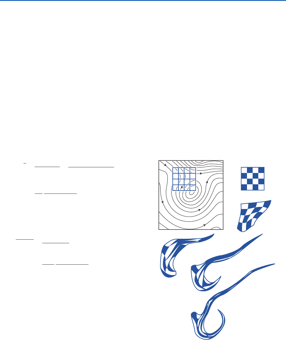
Figure 7.3 illustrates how even a relatively simple
large-scale motion field can distort a field of passive
tracers, initially configured as a rectangular grid,
into an elongated configuration in which the indi-
vidual grid squares are stretched and squashed
beyond recognition. Some squares that were ini-
tially far apart end up close together, and vice versa.
Deformation can sharpen preexisting horizontal
gradients of temperature, moisture, and other scalar
L
A
D
E
B
C
Fig. 7.3 (Top) A grid of air parcels embedded in a steady
state horizontal wind field indicated by the arrows. The
strength of the wind at any point is inversely proportional to
the spacing between the contours at that point. (A–E) How
the grid is deformed by the flow as the tagged particles move
downstream; those in the upper right corner of the grid mov-
ing eastward and those in the lower left corner moving south-
ward and then eastward around the closed circulation. [From
Tellus, 7, 141–156 (1955).]
P732951-Ch07.qxd 12/16/05 11:05 AM Page 274
7.1 Kinematics of the Large-Scale Horizontal Flow 275
variables, creating features referred to as frontal
zones. To illustrate how this sharpening occurs, con-
sider the distribution of a hypothetical passive tracer,
whose concentration
(x, y) is conserved as it is car-
ried around (or advected) in a divergence-free hori-
zontal flow. Because d
dt 0 in (1.3), it follows
that the time rate of change at a fixed point in space
is given by the horizontal advection; that is
(7.5a)
or, in Cartesian coordinates,
(7.5b)
The time rate of change of
at a fixed point (x, y) is
positive if
increases in the upstream direction in
which case V at (x, y) must have a component
directed down the gradient of
; hence the minus
signs in (7.5a,b).
Suppose that
initially exhibits a uniform horizon-
tal gradient, say from north to south. Such a gradient
will tend to be sharpened within regions of negative
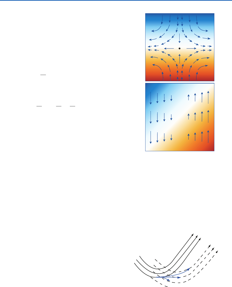
vy. In the pattern of pure deformation in Fig. 7.2d,
vy is negative throughout the domain. Such a flow
will tend to sharpen any preexisting north–south tem-
perature gradient, creating an east–west oriented
frontal zone, as shown in Fig. 7.4a. Frontal zones can
also be twisted and sharpened by the presence of a
wind pattern with shear, as shown in Fig. 7.4b.
7.1.4 Streamlines versus Trajectories
If the horizontal wind field V is changing with time,
the streamlines of the instantaneous horizontal wind
field considered in this section are not the same as
the horizontal trajectories of air parcels. Consider, for
example, the case of a sinusoidal wave that is propa-
gating eastward with phase speed c, superimposed on
a uniform westerly flow of speed U, as depicted in
Fig. 7.5. The solid lines represent horizontal stream-
lines at time t, and the dashed lines represent the
horizontal streamlines at time t
t, after the wave
has moved some distance eastward. The trajectories
originate at point A, which lies in the trough of the
wave at time t. If the westerly flow matches the rate
of eastward propagation of the wave, the parcel will
remain in the wave trough as it moves eastward, as
indicated by the straight trajectory AC. If the west-
t
u
x
v
y
t
V
(b)
(a)
Fig. 7.4 Frontal zones created by horizontal flow patterns
advecting a passive tracer with concentrations indicated by
the colored shading. In (a) the gradient is being sharpened by
deformation, whereas in (b) it is being twisted and sharpened
by shear. See text and Exercise 7.11 for further explanation.
Fig. 7.5 Streamlines and trajectories for parcels in a wave
moving eastward with phase velocity c embedded in a westerly
flow with uniform speed U. Solid black arrows denote initial
streamlines and dashed black arrows denote later stream-
lines. Blue arrows denote air trajectories starting from point A
for three different values of U. AB is the trajectory for U c;
AC for U c, and AD for U c.
A
B
C
D
erly flow through the wave is faster than the rate of
propagation of the wave (i.e., if U c), the air parcel
will overtake the region of southwesterly flow ahead
of the trough and drift northward, as indicated by the
P732951-Ch07.qxd 12/16/05 11:05 AM Page 275
276 Atmospheric Dynamics
trajectory AB. Conversely, if U c, the air parcel will
fall behind the trough of the wave and curve south-
eastward, as indicated by AD. By construction, each
of the three trajectories is parallel to the initial
streamline passing through point A and to the
respective later streamlines passing through points B,
C, and D. The longest trajectory (AB) corresponds to
the highest wind speed.
7.2 Dynamics of Horizontal Flow
Newton’s second law states that in each of the three
directions in the coordinate system, the acceleration
a experienced by a body of mass m in response to a
resultant force F is given by
(7.6)
This relationship describes the motion in an inertial
(nonaccelerating) frame of reference. However, it is
more generally applicable, provided that apparent
forces are introduced to compensate for the accelera-
tion of the coordinate system. In a rotating frame of
reference two different apparent forces are required:
a centrifugal force that is experienced by all bodies,
irrespective of their motion, and a Coriolis force that
depends on the relative velocity of the body in the
plane perpendicular to the axis of rotation (i.e., in the
plane parallel to the equatorial plane).
7.2.1 Apparent Forces
The force per unit mass that is referred to as gravity
or effective gravity and denoted by the symbol g rep-
resents the vectorial sum of the true gravitational
attraction g* that draws all elements of mass toward
Earth’s center of mass and the much smaller appar-
ent force called the centrifugal force
2
R
A
, where
is the rotation rate of the coordinate system in radi-
ans per second (i.e., s
1
) and R
A
is the distance from
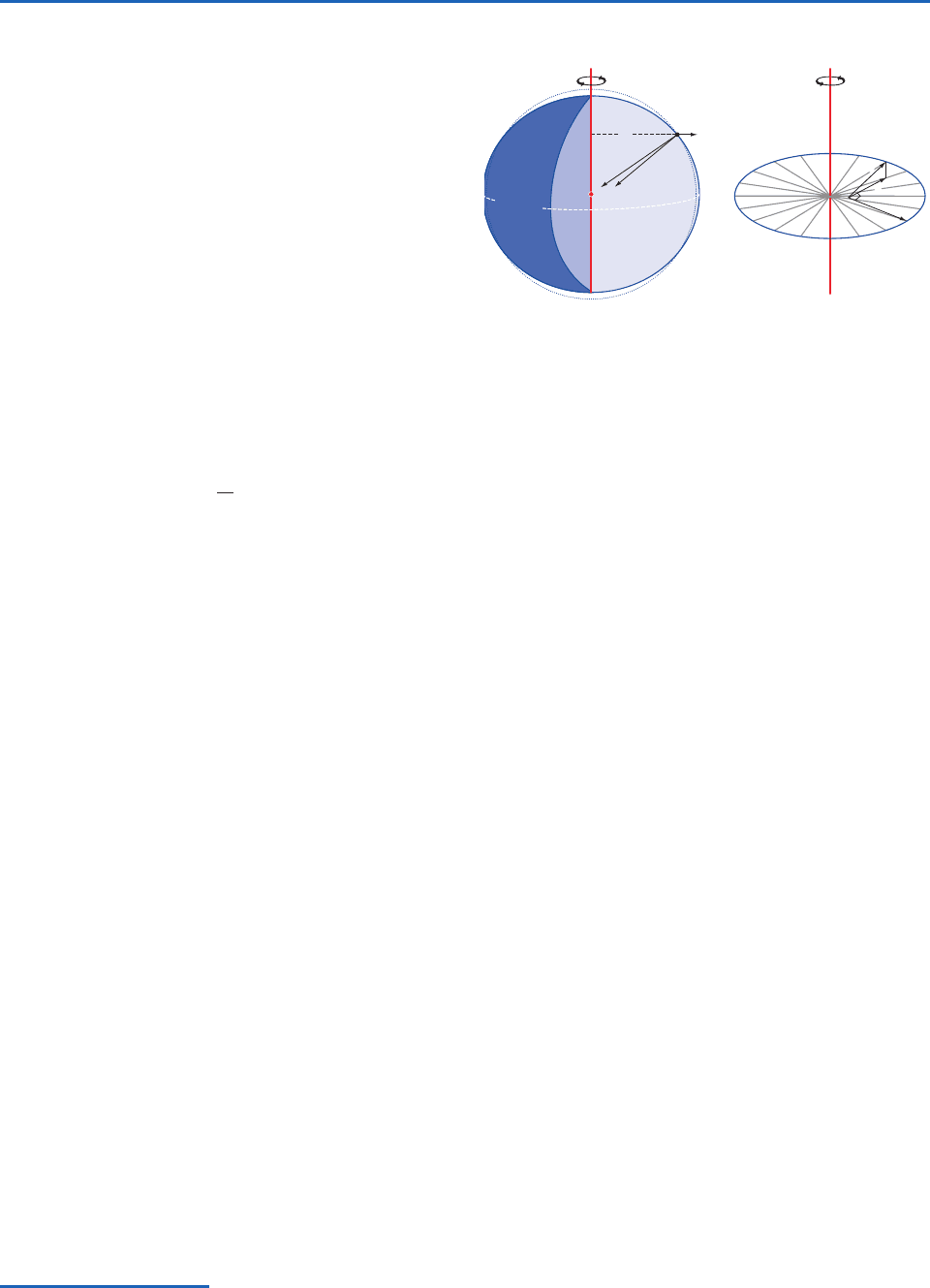
the axis of rotation. The centrifugal force pulls all
objects outward from the axis of planetary rotation,
as indicated in Fig. 7.6. In mathematical notation,
g g*
2
R
A
.
a
1
m
F
Surfaces of constant geopotential , which are
normal to g, are shaped like oblate spheroids, as indi-
cated by the outline of the Earth in Fig. 7.6. Because
the surface of the oceans and the large-scale configu-
ration of the Earth’s crust are incapable of resisting
any sideways pull of effective gravity, they have
aligned themselves with surfaces of constant geopo-
tential. A body rotating with the Earth has no way of
separately sensing the gravitational and centrifugal
components of effective gravity. Hence, the
2
R
A
term is incorporated into g in the equations of
motion.
An object moving with velocity c in the plane per-
pendicular to the axis of rotation experiences an
additional apparent force called the Coriolis
2
force
2c. This apparent force is also in the plane per-
pendicular to the axis of rotation, and it is directed
transverse to the motion in accordance with the right
hand rule (i.e., if the rotation is counterclockwise
when viewed from above, the force is directed to the
right of c and vice versa).
When the forces and the motions are represented
in a spherical coordinate system, the horizontal
component of the Coriolis force arising from the
(a) (b)
Ω
c′
c
C
Ω
2
R
A
R
A
Ω
g
g*
P
Equator
O
Fig. 7.6 (a) Apparent forces. Effective gravity g is the vecto-
rial sum of the true gravitational acceleration g* directed
toward the center of the Earth O and the centrifugal force
2
R
A
.
The acceleration g is normal to a surface of constant geopo-
tential, an oblate spheroid, depicted as the outline of the
Earth. The dashed reference line represents a true spherical
surface. (b) The Coriolis force C is linearly proportional to c
the component of the relative velocity c in the plane perpendi-
cular to the axis of rotation. When viewed from a northern
hemisphere perspective, C is directed to the right of c and lies
in the plane perpendicular to the axis of rotation.
2
G. G. de Coriolis (1792–1843) French engineer, mathmatician, and physicist. Gave the first modern definition of kinetic energy and
work. Studied motions in rotating systems.
P732951-Ch07.qxd 12/16/05 11:05 AM Page 276
7.2 Dynamics of Horizontal Flow 277
horizontal motion V can be written in vectorial
form as
(7.7)
where f, the so-called Coriolis parameter, is equal to
2 sin
and k is the local vertical unit vector, defined
as positive upward. The sin
term in f appropriately
scales the Coriolis force to account for the fact that the
local vertical unit vector k is parallel to the axis of rota-
tion only at the poles. Accordingly, the Coriolis force
C f k
V
in the horizontal equation of motion increases with lat-
itude from zero on the equator to 2V at the poles,
where V is the (scalar) horizontal wind speed. The
Coriolis force is directed toward the right of the hori-
zontal velocity vector in the northern hemisphere and
to the left of it in the southern hemisphere. On Earth
where day in this context refers to the sidereal day,
3
which is 23 h 56 min in length.
2
rad day
1
7.292 10
5
s
1
3
The time interval between successive transits of a star over a meridian.
The role of the Coriolis force in a rotating coor-
dinate system can be demonstrated in laboratory
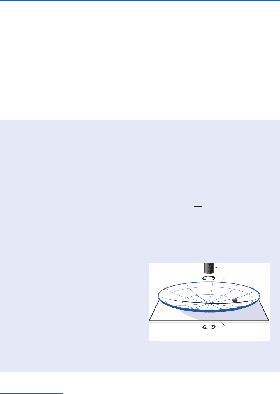
experiments. Here we describe an experiment that
makes use of a special apparatus in which the cen-
trifugal force is incorporated into the vertical
force called gravity, as it is on Earth. The appara-
tus consists of a shallow dish, rotating about its
axis of symmetry as shown in Fig. 7.7. The rotation
rate is tuned to the concavity of the dish such
that at any given radius the outward-directed cen-
trifugal force exactly balances the inward-directed
component of gravity along the sloping surface of
the dish; that is
where z is the height of the surface above some
arbitrary reference level, r is the radius, and is
the rotation rate of the dish. Integrating from the
center out to radius r yields the parabolic surface
The constant of integration is chosen to make z
0 the level of the center of the dish.
Consider the horizontal trajectory of an ideal-
ized frictionless marble rolling around in the dish,
as represented in both a fixed (inertial) frame of
z
2
r
2
2
constant
dz
dr
2
r
reference and in a frame of reference rotating
with the dish. (To view the motion in the rotating
frame of reference, the video camera is mounted
on the turntable.)
In the fixed frame of reference the differential
equation governing the horizontal motion of the
marble is
It follows from the form of this differential equa-
tion that the marble will execute elliptical trajec-
tories, symmetric about the axis of rotation, with
d
2
r
dt
2
2
r
7.1 Experiment in a Dish
Continued on next page
Axis of rotation
Camera
Parabolic surface
Rotating turntable
Fig. 7.7 Setup for the rotating dish experiment. Radius r is
distance from the axis of rotation. Angular velocity is the
rotation rate of the dish. See text for further explanation.
P732951-Ch07.qxd 12/16/05 11:05 AM Page 277
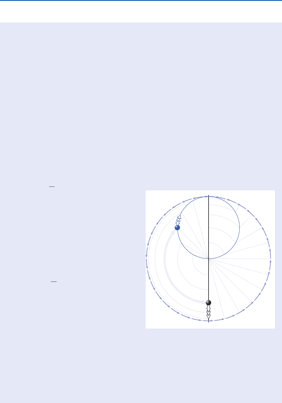
278 Atmospheric Dynamics
period 2
, which exactly matches the period of
rotation of the dish. The shape and orientation of
these trajectories will depend on the initial posi-
tion and velocity of the marble. In this example,
the marble is released at radius r r
0
with no ini-
tial velocity. After the marble is released it rolls
back and forth, like the tip of a pendulum, along
the straight line pictured in Fig. 7.7, with a period
equal to 2
, the same as the period of rotation
of the dish. This oscillatory solution is represented
by the equation
where t is time and radius r is defined as positive
on the side of the dish from which the marble is
released and negative on the other side. The veloc-
ity of the marble along its pendulum-like trajectory
is largest at the times when it passes through the
center of the dish at t
2, 3
2..., and the
marble is motionless for an instant at t
,2
...
when it reverses direction at the outer edge of its
trajectory.
In the rotating frame of reference the only
force in the horizontal equation of motion is the
Coriolis force, so the governing equation is
where c is the velocity of the marble and k is the
vertical (normal to the surface of the dish) unit
vector. Because dcdt is perpendicular to c, it fol-
lows that c, the speed of the marble as it moves
along its trajectory in the rotating frame of refer-
ence, must be constant. The direction of the for-
ward motion of the marble is changing with time at
the uniform rate 2, which is exactly twice the rate
of rotation of the dish. Hence, the marble executes
a circular orbit called an inertia circle, with period
2
2
(i.e., half the period of rotation of
the dish), with circumference c (
), and radius
c (
)2
c2. Because dcdt is to the right
dc
dt
2k c
dr
dt
r
0
sin t
r r
0
cos t
of c, it follows that the marble rolls clockwise,
i.e., in the opposite sense as the rotation of the dish.
As in the fixed frame of reference, the trajec-
tory of the marble depends on its initial position
and relative motion. Because the marble is
released at radius r
0
with no initial motion in the
fixed frame of reference, it follows that its speed
in the rotating frame of reference is c r
0
, and
thus the radius of the inertia circle is r
0
2
r
0
2. It follows that the marble passes through the
center of the dish at the midpoint of its trajectory
around the inertia circle.
The motion of the marble in the fixed and rotat-
ing frames of reference is shown in Fig. 7.8. The
rotating dish is represented by the large circle. The
point of release of the marble is labeled 0 and
appears at the top of the diagram rather than on
the left side of the dish as in Fig. 7.7. The pendu-
lum-like trajectory of the marble in the fixed
frame of reference is represented by the straight
7.1 Continued
1
2
3
4
5
6
7
8
9
10
11
12
8
7
9
11
0
10
1
1
2
2
3
3
4
4
5
5
6
7
8
9
10
11
Fig. 7.8 Trajectories of a frictionless marble in fixed
(black) and rotating (blue) frames of reference. Numbered
points correspond to positions of the marble at various
times after it is released at point 0. One complete rotation
of the dish corresponds to one swing back and forth along
the straight vertical black line in the fixed frame of reference
and two complete circuits of the marble around the blue
inertia circle in the rotating frame of reference. The light
lines are reference lines. See text for further explanation.
P732951-Ch07.qxd 12/16/05 11:05 AM Page 278

7.2 Dynamics of Horizontal Flow 279
7.2.2 Real Forces
The real forces that enter into the equations of
motion are gravity, the pressure gradient force, and
frictional force exerted by neighboring air parcels or
adjacent surfaces.
a. The pressure gradient force
The vertical component of the pressure gradient
force (per unit mass) (1
)pz has already been
introduced in the context of the hydrostatic equa-
tion. The horizontal component of the pressure gra-
dient force is given by the analogous expression
(7.8a)
or, in component form,
(7.8b)
The pressure gradient force is directed down the hori-
zontal pressure gradient p from higher toward lower
pressure. Making use of the hydrostatic equation
(3.17) and the definitions of geopotential (3.20) and
geopotential height (3.22), the horizontal pressure
P
x
1
p
x
; P
y
1
p
y
P
1
p
gradient force can be expressed in the alternative
forms
(7.9)
where the gradients of geometric height, geopotential
height, and geopotential are defined on sloping pres-
sure surfaces. Hence, the pressure gradient force can be
interpreted as the component of effective gravity
in
the plane of the pressure surface, analogous to the
“downhill” force on a ball rolling on a sloping surface.
Pressure surfaces exhibit typical slopes on the order of
100 m per thousand kilometers, or 1 in 10
4
. Hence, the
horizontal component of the pressure gradient force is
roughly four orders of magnitude smaller than the ver-
tical component; i.e., it is on the order of 10
3
m s
2
.
The pressure field on weather charts is typically rep-
resented by a set of contours plotted at regularly
spaced intervals as in Fig. 1.19. The lines that are used
to depict the distribution of pressure on geopotential
height surfaces are referred to as isobars, and the lines
used to depict the distribution of geopotential height
on pressure surfaces are referred to as geopotential
height contours. Exercise 3.3 demonstrates that, to a
close approximation, isobars on a constant geopotential
surface (e.g., sea level) can be converted into geopoten-
tial height contours on a nearby pressure surface simply
by relabeling them using a constant of proportionality
P
z
0
Z
7.1 Continued
black vertical line passing through the center of
the dish. Successive positions along the trajectory
at equally spaced time intervals are represented
by numbers: point 1 represents the position of
the marble after 124 of the period of rotation of
the dish, point 12 after one-half period of rotation,
etc. Hence, the numerical values assigned to the
points are analogous to the 24 h of the day on a
rotating planet. Note that the spacing between
successive points is largest near the middle of
the pendulum-like trajectory, where the marble is
rolling fastest.
The position of the marble in the rotating
(blue) frame of reference can be located at any
specified time without invoking the Coriolis force
simply by subtracting the displacement of the dish
from the displacement of the marble in the fixed
frame of reference. For example, to locate the
marble after one-eighth rotation of the dish, we
rotate point 3 clockwise (i.e., in the direction
opposite to the rotation of the dish) one-eighth of
the way around the circle; point 9 needs to be
rotated three-eighths of the way around the cir-
cle, and so forth. The rotated points map out the
trajectory of the marble in the rotating frame of
reference: an inertia circle with a period equal to
one-half revolution of the dish (i.e., 12 “hours”).
In Fig. 7.8 the marble is pictured at 9 o’clock on
the 24-hour clock in the two frames of reference.
Alternatively, the inertia circle can be con-
structed by first rotating the marble backward
(clockwise) from its point of release to subtract
the rotation of the dish and then moving the mar-
ble radially the appropriate distance along its
pendulum-like trajectory. Reference lines for per-
forming these operations are shown in Fig. 7.8.
Examples of trajectories for two other sets of ini-
tial conditions are presented in Exercise 7.14.
P732951-Ch07.qxd 12/16/05 11:05 AM Page 279

280 Atmospheric Dynamics
based on the hypsometric equation (3.29). For example,
near sea level, where atmospheric pressure decreases
with height at a rate of 1 hPa per 8 m, the conven-
tional 4-hPa contour interval for isobars of sea-level
pressure is approximately equivalent to a 30-m contour
interval for geopotential height contours on a specified
pressure surface. It follows that (7.8) and (7.9) yield vir-
tually identical distributions of P.
In the oceans the horizontal pressure gradient force
is due to both the gradient in sea level on a surface of
constant geopotential and horizontal gradients in the
density of the overlying water in the column. Near the
ocean surface this force is primarily associated with
the horizontal gradient in sea level. The topography of
sea level is difficult to estimate in an absolute sense
from observations because Earth’s geoid (i.e., geopo-
tential field) exhibits nonellipsoidal irregularities of its
own that have more to do with plate tectonics than
with oceanography. Temporal variations in sea level
relative to Earth’s much more slowly evolving geoid
are clearly revealed by satellite altimetry.
b. The frictional force
The frictional force (per unit mass) is given by
(7.10)
where
represents the vertical component of the
shear stress (i.e., the rate of vertical exchange of hori-
zontal momentum) in units of N m
2
due to the pres-
ence of smaller, unresolved scales of motion.
4
Vertical exchanges of momentum usually act to
smooth out the vertical profile of V.The rate of verti-
cal mixing that is occurring at any particular level
and time depends on the strength of the vertical wind
shear Vz and on the intensity of the unresolved
motions, as discussed in Chapter 9. In the free atmos-
phere, above the boundary layer, the frictional force
is much smaller than the pressure gradient force and
the Coriolis force. However, within the boundary
layer the frictional force is comparable in magnitude
to the other terms in the horizontal equation of
motion and needs to be taken into account.
The shear stress
s
at the Earth’s surface is in the
opposing direction to the surface wind vector V
s
F
1
z
(i.e., it is a “drag” on the surface wind) and can be
approximated by the empirical relationship
(7.11)
where
is the density of the air, C
D
is a dimension-
less drag coefficient, the magnitude of which varies
with the roughness of the underlying surface and the
static stability, V
s
is the surface wind vector, and V
s
is
the (scalar) surface wind speed. Within the lowest
few tens of meters of the atmosphere, the stress
decreases with height without much change in direc-
tion. Hence, within this so-called surface layer, the
frictional force F
s
z is directed opposite to
V
s
and is referred to as frictional drag.
7.2.3 The Horizontal Equation of Motion
The horizontal component of (7.6), written in vecto-
rial form, per unit mass, is
(7.12)
where dVdt is the Lagrangian time derivative of the
horizontal velocity component experienced by an air
parcel as it moves about in the atmosphere.
Substituting for C from (7.7) and for P from (7.8a) we
obtain
(7.13a)
or, in component form on a tangent plane (i.e.,
neglecting smaller terms that arise due to the curva-
ture of the coordinate system),
(7.13b)
The density dependence can be eliminated by substi-
tuting for P using (7.9) instead of (7.8), which yields
(7.14)
dV
dt
f k V F
dv
dt
1
p
y
fu F
y
du
dt
1
p
x
fv F
x
,
dV
dt
1
p f k V F
dV
dt
P C F
s
C
D
V
s
V
s
4
The contributions of the corresponding horizontal exchanges of momentum to F do not need to be considered because the horizontal
gradients are much smaller than the vertical gradients.
P732951-Ch07.qxd 12/16/05 11:05 AM Page 280
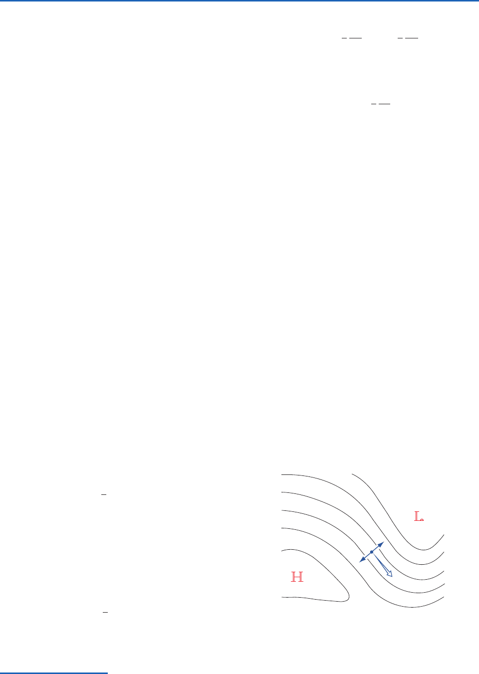
7.2 Dynamics of Horizontal Flow 281
In (7.13a) the horizontal wind field is defined on sur-
faces of constant geopotential so that 0, whereas
in (7.14) it is defined on constant pressure surfaces so
that p 0. However, pressure surfaces are suffi-
ciently flat that the V fields on a geopotential surface
and a nearby pressure surface are very similar.
7.2.4 The Geostrophic Wind
In large-scale wind systems such as baroclinic waves
and extratropical cyclones, typical horizontal velocities
are on the order of 10 m s
1
and the timescale over
which individual air parcels experience significant
changes in velocity is on the order of a day or so
(10
5
s). Thus a typical parcel acceleration dVdt is
10 m s
1
per 10
5
s or 10
4
ms
2
. In middle latitudes,
where f 10
4
s
1
, an air parcel moving at a speed of
10 m s
1
experiences a Coriolis force per unit mass C
10
3
ms
2
, about an order of magnitude larger than
the typical horizontal accelerations of air parcels.
In the free atmosphere, where the frictional force
is usually very small, the only term that is capable of
balancing the Coriolis force C is the pressure gradi-
ent force P. Thus, to within about 10%, in middle
and high latitudes, the horizontal equation of motion
(7.14) is closely approximated by
Making use of the vector identity
it follows that
For any given horizontal distribution of pressure on
geopotential surfaces (or geopotential height on pres-
sure surfaces) it is possible to define a geostrophic
5
wind field V
g
for which this relationship is exactly
satisfied:
(7.15a)
or, in component form,
V
1
f
(k )
V
1
f
(k )
k (k V) V
f k V
(7.15b)
or, in natural coordinates,
(7.15c)
where V
is the scalar geostrophic wind speed and n
is the direction normal to the isobars (or geopoten-
tial height contours), pointing toward higher values.
The balance of horizontal forces implicit in the
definition of the geostrophic wind (for a location in
the northern hemisphere) is illustrated in Fig. 7.9. In
order for the Coriolis force and the pressure gradient
force to balance, the geostrophic wind must blow
parallel to the isobars, leaving low pressure to the
left. In either hemisphere, the geostrophic wind field
circulates cyclonically around a center of low pres-
sure and vice versa, as in Fig. 1.14, justifying the iden-
tification of local pressure minima with cyclones and
local pressure maxima with anticyclones. The tighter
the spacing of the isobars or geopotential height con-
tours, the stronger the Coriolis force required to bal-
ance the pressure gradient force and hence, the
higher the speed of the geostrophic wind.
7.2.5 The Effect of Friction
The three-way balance of forces required for flow in
which dVdt 0 in the northern hemisphere in the
presence of friction at the Earth’s surface is illus-
trated in Fig. 7.10. As in Fig. 7.9, P is directed normal
V
1
f
n
u
1
f
y
, v
1
f
x
5
From the Greek: geo (Earth) and strophen (to turn)
Fig. 7.9 The geostrophic wind V
and its relationship to the
horizontal pressure gradient force P and the Coriolis force C
in the northern hemisphere.
C
P
V
g
P732951-Ch07.qxd 12/16/05 11:05 AM Page 281
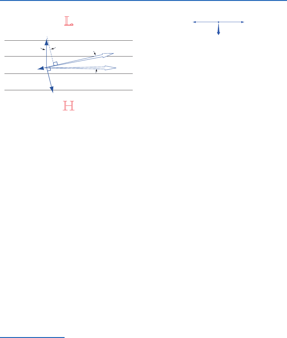
282 Atmospheric Dynamics
to the isobars, C is directed to the right of the hori-
zontal velocity vector V
s
, and, consistent with (7.11),
F
s
is directed opposite to V
s
. The angle
between V
s
and V
is determined by the requirement that the
component of P in the forward direction of V
s
must
be equal to the magnitude of the drag F
s
, and the
wind speed V
s
is determined by the requirement that
C be just large enough to balance the component of
P in the direction normal to V
s
; i.e.,
It follows that sCssPs and, hence, the scalar wind
speed V
s
sCsf must be smaller than V
sPsf.
The stronger the frictional drag force F
s
, the larger
the angle
between V
and V
s
and the more sub-
geostrophic the surface wind speed V
s
. The cross-
isobar flow toward lower pressure, referred to as the
Ekman
6
drift, is clearly evident on surface charts, par-
ticularly over rough land surfaces. That the winds
fV
s
&P&cos
usually blow nearly parallel to the isobars in the free
atmosphere indicates that the significance of the
frictional drag force is largely restricted to the
boundary layer, where small-scale turbulent motions
are present.
The same shear stress that acts as a drag force on
the surface winds exerts a forward pull on the surface
waters of the ocean, giving rise to wind-driven cur-
rents. If the ocean surface coincided with a surface of
constant geopotential, the balance of forces just
below the surface would consist of a two-way bal-
ance between the forward pull of the surface wind
and the backward pull of the Coriolis force induced
by the Ekman drift, as shown in Fig. 7.11. Although
the large scale surface currents depicted in Fig. 2.4
tend to be in geostrophic balance and oriented
roughly parallel to the mean surface winds, the
Ekman drift, which is directed normal to the surface
winds, has a pronounced effect on horizontal trans-
port of near-surface water and sea-ice, and it largely
controls the distribution of upwelling, as discussed in
Section 7.3.4. Ekman drift is largely confined to the
topmost 50 m of the oceans.
7.2.6 The Gradient Wind
The centripetal accelerations observed in association
with the curvature of the trajectories of air parcels
tend to be much larger than those associated with
Fig. 7.10 The three-way balance of forces required for
steady surface winds in the presence of the frictional drag
force F in the northern hemisphere. Solid lines represent iso-
bars or geopotential height contours on a weather chart.
P
F
s
V
s
ψ
ψ
C
V
g
6
V. Walfrid Ekman (1874–1954) Swedish oceanographer. Ekman was introduced to the problem of wind-driven ocean circulation
when he was a student working under the direction of Professor Vilhelm Bjerknes.
7
Fridtjof Nansen had approached Bjerknes with a
remarkable set of observations of winds and ice motions taken during the voyage of the Fram, for which he sought an explanation.
Nansen’s observations and Ekman’s mathematical analysis are the foundations of the theory of the wind-driven ocean circulation.
7
Vilhelm Bjerknes (1862–1951) Norwegian physicist and one of the founders of the science of meteorology. Held academic positions
at the universities of Stockholm, Bergen, Leipzig, and Kristiania (renamed Oslo). Proposed in 1904 that weather prediction be regarded
as an initial value problem that could be solved by integrating the governing equations forward in time, starting from an initial state
determined by current weather observations. Best known for his work at Bergen (1917–1926) where he assembled a small group of dedi-
cated and talented young researchers, including his son Jakob.The most widely recognized achievement of this so-called “Bergen School”
was a conceptual framework for interpreting the structure and evolution of extratropical cyclones and fronts that has endured until the
present day.
Fig. 7.11 The force balance associated with Ekman drift in
the northern hemisphere oceans. The frictional force F is in
the direction of the surface wind vector. In the southern hemi-
sphere (not shown) the Ekman drift is to the left of the sur-
face wind vector.
CF
V
Ekman
P732951-Ch07.qxd 12/16/05 11:05 AM Page 282
7.2 Dynamics of Horizontal Flow 283
the speeding up or slowing down of air parcels as
they move downstream. Hence, when dVdt is large,
its scalar magnitude can be approximated by the
centripetal acceleration V
2
R
T
, where R
T
is the local
radius of curvature of the air trajectories.
8
Hence,
the horizontal equation of motion reduces to the
balance of forces in the direction transverse to the
flow, i.e.,
(7.16)
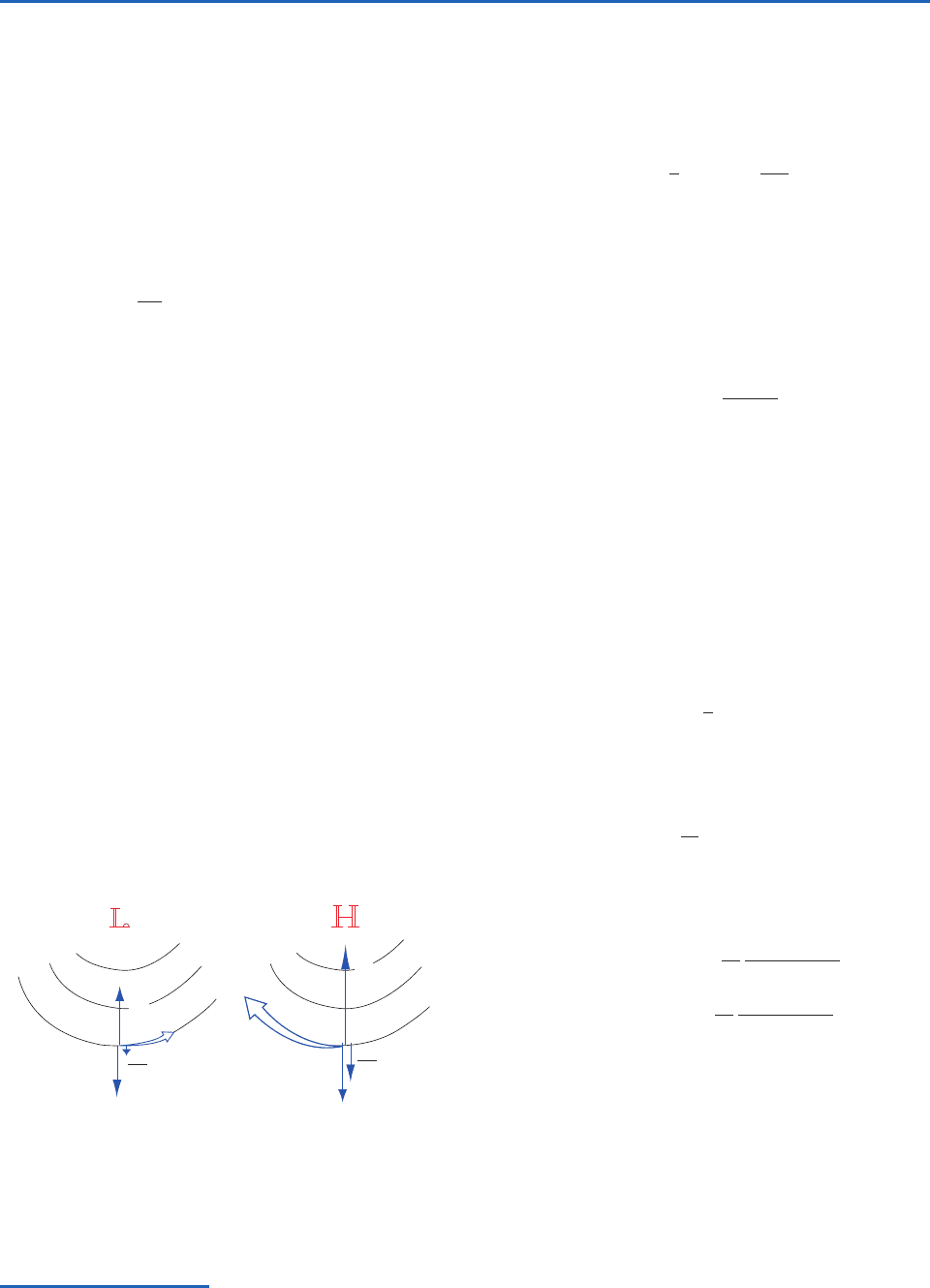
The signs of the terms in this three-way balance
depend on whether the curvature of the trajectories
is cyclonic or anticyclonic, as illustrated in Fig. 7.12.
In the cyclonic case, the outward centrifugal force
(the mirror image of the centripetal acceleration)
reinforces the Coriolis force so that a balance can be
achieved with a wind speed smaller than would be
required if the Coriolis force were acting alone. In
flow through sharp troughs, where the curvature of
the trajectories is cyclonic, the observed wind speeds
at the jet stream level are often smaller, by a factor of
two or more, than the geostrophic wind speed
implied by the spacing of the isobars. For the anticy-
clonically curved trajectory on the right in Fig. 7.12
the centrifugal force opposes the Coriolis force,
necessitating a supergeostrophic wind speed in order
to achieve a balance.
The wind associated with a three-way balance
between the pressure gradient and Coriolis and
n
V
2
R
T
f k V
centrifugal forces is called the gradient wind.The
solution of (7.16), which yields the speed of the gra-
dient wind can be written in the form
(7.17)
and solved using the quadratic formula. From
Fig. 7.12, it can be inferred that R
T
should be speci-
fied as positive if the curvature is cyclonic and nega-
tive if the curvature is anticyclonic. For the case of
anticyclonic curvature, a solution exists when
7.2.7 The Thermal Wind
Just as the geostrophic wind bears a simple relation-
ship to , the vertical shear of the geostrophic wind
bears a simple relationship to T. Writing the
geostrophic equation (7.15a) for two different pres-
sure surfaces and subtracting, we obtain an expres-
sion for the vertical wind shear in the intervening
layer
(7.18)
In terms of geopotential height
(7.19a)
or in component form,
(7.19b)
This expression, known as the thermal wind equation,
states that the vertically averaged vertical shear of the
geostrophic wind within the layer between any two
pressure surfaces is related to the horizontal gradient
of thickness of the layer in the same manner in which
geostrophic wind is related to geopotential height. For
example, in the northern hemisphere the thermal wind
(v
)
2
(v
)
1
0
f
(Z
2
Z
1
)
x
(u
)
2
(u
)
1
0
f
(Z
2
Z
1
)
y
,
(V
)
2
(V
)
1
0
f
k (Z
2
Z
1
)
(V
)
2
(V
)
1
1
f
k (
2
1
)
&&
f
2
R
T
4
V
r
1
f
&&
V
2
r
R
T
8
In estimating the radius of curvature in the gradient wind equation it is important to keep in mind the distinction between streamlines
and trajectories, as explained in Section 7.1.4.
Fig. 7.12 The three-way balance involving the horizontal pres-
sure gradient force P, the Coriolis force C, and the centrifugal
force sVs
2
R
T
in flow along curved trajectories in the northern
hemisphere. (Left) Cyclonic flow. (Right) Anticyclonic flow.
V
2
R
T
V
2
R
T
V
gr
C
P
V
gr
C
P
P732951-Ch07.qxd 12/16/05 11:05 AM Page 283
