Tsch?tsch H., Koth A. Metal Forming Practise: Processes - Machines - Tools
Подождите немного. Документ загружается.

24.6 Example 311
2. Work capacity of the press in continuous mode W
ct
n
ct
20 00 kN 200 mm
26 666.7 kN mm
15 15
FH
W
3. Comparison of both work capacities.
The work capacity of the press in continuous mode, W
ct
, is higher than that required for the
deformation, W
F1
W
ct
> W
F1
26 666.7 kN mm > 24 000 kN mm
i.e. the press can be used for this operation in continuous mode.
4. Assessing the forces.
4.1. Nominal press force F
n
The nominal press force is higher than the force required for the deformation
F
n
> F
F1
2000 kN > 1200 kN
For this reason, the press can be used for this operation from the point of view of the nominal
press force.
4.2. Determining the permissible press force F
M
from the drive moment
nmax
M
222
adj
2000 kN 200 mm
1 666.7 kN
4420020mm20mm
FH
F
Hhh
The permissible press force resulting from the drive moment and taking into account the stroke
is higher than the extrusion force,
F
M
> F
F1
1666.7 kN > 1200 kN
meaning that the press can also be used from this point of view.
4.3. Determining the permissible press force from the continuous work capacity of the press
ct
ct
W
26 666.7 kN
1333.3 kN
20mm
W
F
h
F
W
ct
> F
F1
so it can be used.
Decision: As the permissible forces and the continuous work capacity of the press are higher
under the given conditions than the deformation forces and the work capacity required for the
deformation, the press can be used.

312 24 Eccentric and crank presses
24.7 Application of eccentric and crank presses
Eccentric presses
are mainly used for blanking, embossing and bending, as long as only small displacements are
required, as the eccentric demands.
Crank presses
are used for all chipless forming methods where the deformation force does not have to be
constant over a long distance, i.e. for the forward extrusion of short components, deep draw-
ing, bending and impression-die forging on heavy forging presses.
24.8 Exercise on Chapter 24
1. What kinds of frame construction are there for eccentric and crank presses?
2. Why is the press frame’s resistance to deflection of great importance?
3. What kinds of drive are there for eccentric and crank presses?
4. What kinds of clutches are there for crank presses?
5. What load-limiting safety devices do you know?
6. How is the ram stroke length adjusted on an eccentric press?
7. How is an eccentric press protected against overload?
8. What different types of eccentric and crank press construction are there?
25 Knuckle-joint and toggle presses
25.1 Single-point knuckle-joint presses
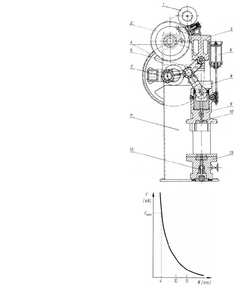
Knuckle-joint presses (Figure 25.1) are a
special kind of crank press where the crank
force is produced via a (knuckle joint) joint
system. In principle, the rules which govern
a crank press apply here, both as concerns
the construction design and the way it
works.
The ram velocity path depending upon the
crank angle, and the force-displacement
diagram, are unlike a crank press (Figure
25.2). The nominal press force on a
knuckle-joint press only appears at 3 to 4
mm before BDC (at
D
n
= 32° nominal
crank angle). When the punch displacement
is higher the force drops steeply (hyper-
bolically).
Figure 25.1
Drive layout of a knuckle-joint press. 1 driving
motor, 2 flywheel, 3 head, 4 gear drive, 5 rocker
arm, 6 cylinder to counterbalance the ram mass,
7 connecting rod, 8 push rod, 9 ram, 10 ejector,
11 column, 12 ejector, 13 platen (Illustration:
Kieserling & Albrecht works, Solingen, Ger-
many)
This is particularly important to know for a
works engineer as the operation of these
presses results from the shape of the force-
displacement curve. They are used for
operations which require high press forces
over a short deformation distance. Typical
fields of application for knuckle-joint pres-
ses are sizing, pancaking, coining and
backward extrusion (of tubes).
Figure 25.2 Force-displacement diagram
for a knuckle-joint press
314 25 Knuckle-joint and toggle presses
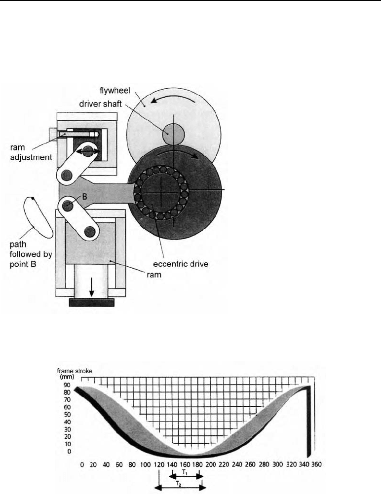
25.2 Toggle presses – modified knuckle-joint presses
Because of the poor force-displacement path with conventional knuckle-joint presses with one
joint, the toggle press was developed, with a modified drive by means of two joints (Figure
25.3).
Figure 25.3
Toggle press (Illustration: Schuler
works, Göppingen, Germany)
The toggle press is anchored in the head. The upper joint pivots in this anchor while the lower
joint follows an curved path. This means that the ram path changes. This path (Figure 25.4)
can be modified by changing the arrangement of the joints.
Figure 25.4 Time-displacement diagram for a toggle press
Crank angle
D
c
(degrees); time until plastic flow:
T
1
for knuckle joint or eccentric presses
T
2
for toggle drives
25.2 Toggle presses – modified knuckle-joint presses 315
As a rule, the aim is to reduce the velocity of the ram in the operating range (e.g. reduce the
impact velocity of the ram). Another advantage for bulk forming is the ram displacement
which can be achieved on this drive system when the operational speed and drive moment are
constant, which is three to four times longer than that of eccentric presses. The time-
displacement diagram (Figure 25.4) shows the slower movement of the ram with a toggle
press. This leaves the material near the bottom dead centre with enough time to reach plastic
flow.
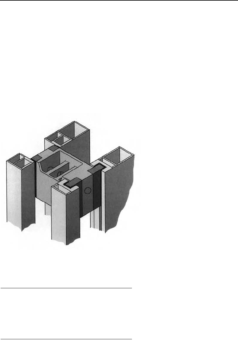
Figure 25.5 shows a vertical cold extrusion transfer press with a toggle drive. A two-piece
welded press frame calculated by FEM is pre-tensioned using tie rods. One distinctive feature
is the cross-shaped eight-part ram guide system with no play (Figure 25.6). This construction
makes the system highly sway-resistant, guaranteeing high workpiece quality and optimum
tool lives.
Figure 25.5
The principle of a cross-shaped eight-
part ram guide
(Illustration: Schuler works, Göppin-
gen, Germany)
The following table contains the dimensions of this press.
Table 25.1 Technical specifications of a cold extrusion transfer press.
Nominal press force in kN 4.000 to 16.000
Nominal force distance in mm 10 to 25
Ram stroke in mm 180 to 520
Strokes per minute in l/min 30 to 60
Work capacity in kJ 50 to 270
Drive power in kN 90 to 300
316 25 Knuckle-joint and toggle presses
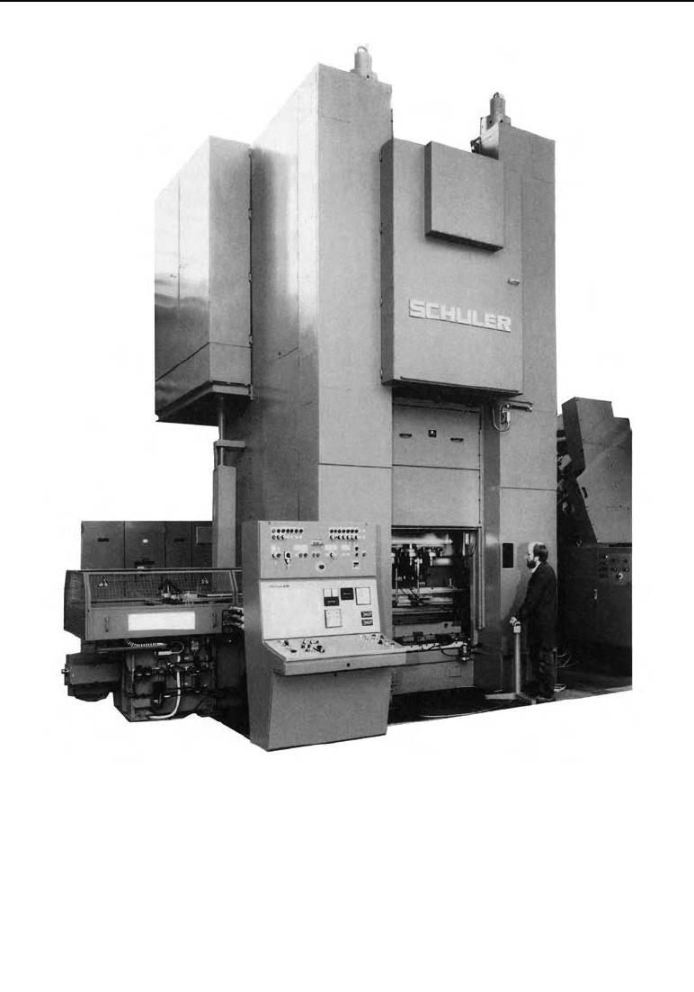
Figure 25.6 Vertical cold extrusion transfer press with toggle drive (Photograph: Schuler works,
Göppingen, Germany)
These presses have a generously-sized housing to hold tooling for up to six operations.
These presses are powered with variable-speed DC motors. The clutch and brakes are oper-
ated electropneumatically, and are mounted apart for thermal reasons.
25.4 Exercise on Chapter 25 317
25.3 Horizontal knuckle-joint and toggle presses
To produce tubes and similar thin-walled hol-
low parts, presses are generally used with a
horizontal layout (Figure 25.7) as it is easier to
feed in the blanks and convey away the fin-
ished parts.
Figure 25.7
Horizontal toggle press to manufacture tubes (Illus-
tration: Herlan & Co. works, Karlsruhe, Germany)
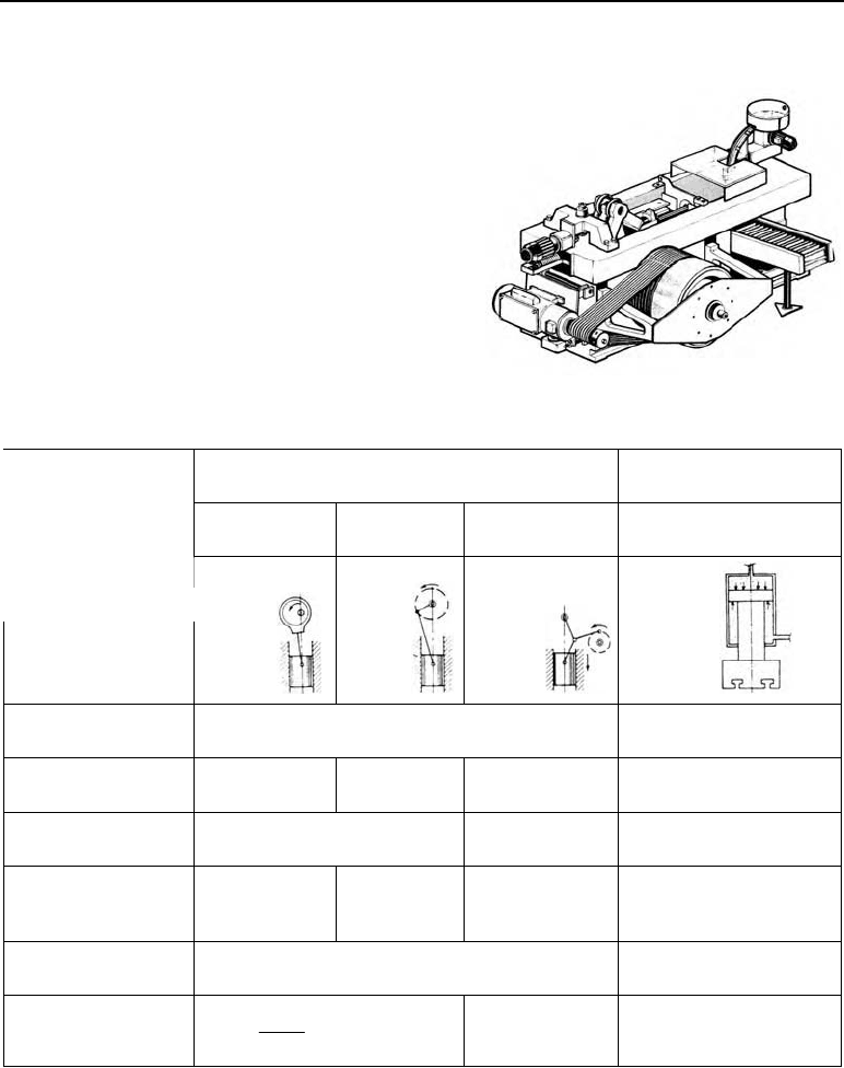
Table 25.2 Characteristics of eccentric, crank, knuckle joint / toggle and hydraulic presses. 1
Presses controlled by the ram path Presses controlled by
force
Eccentric press Crank press Knuckle-joint or
toggle press
Hydraulic press
Characteristic
Energy transmission
Con rod Con rod Con rod Piston rod
Energy for movement Energy storage í flywheel Pressurised oil p = 100
to 315 bar
Effective stroke range
(mm)
10 – 80 100 – 300 3 – 12 100 – 1000
Max. nominal press
force F
N
(kN)
1000 to 16 000 1000 to 16 000 1000 to 16 000
Number of continu-
ous strokes
n
ct
in min
–1
10 to 100 10 to 100 20 to 200 5 to 60
Work capacity W
(kNm) W = F
N
h
N
F
max
· h
max
Nominal press force
F
N
(kN)
N
sin
T
F
D
graphical analy-
sis
F = p · A – R
25.4 Exercise on Chapter 25
1. What differences are there between a knuckle-joint or toggle press and a crank press?
2. When are horizontal knuckle-joint presses often used?
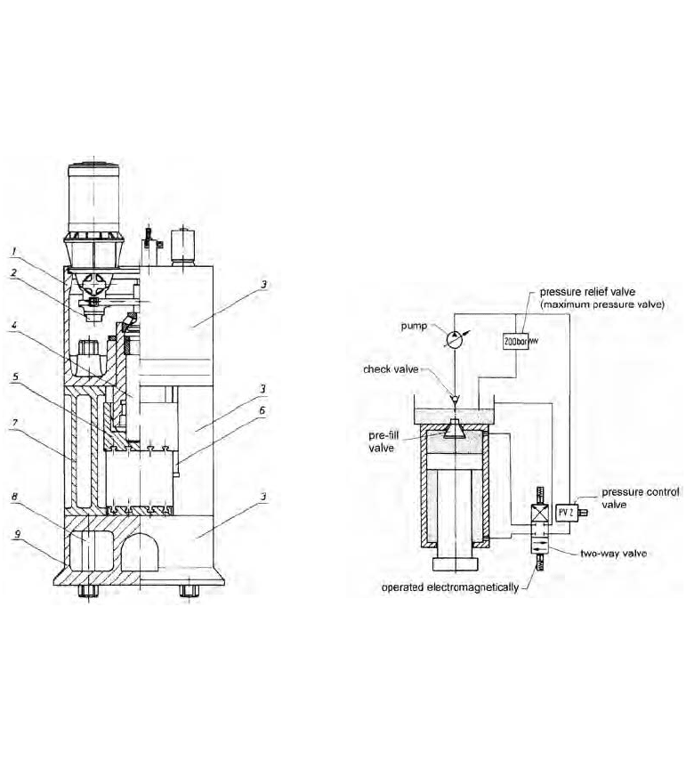
26 Hydraulic presses
The frames of hydraulic presses are mainly built as welded steel O-frames (straight-side fra-
mes) (Figure 26.1). In smaller presses the frame is built in one piece and in larger presses in
three pieces. The three main elements (bottom platen, side columns and head) are held together
with tie rods.
26.1 Hydraulic press drives
The ram movement (Figure 26.2) is produced by a differential piston. In small presses, the
required amount of compressed oil is provided by means of constant feed pumps (gear or
screw pumps) and in larger presses by adjustable axial or radial piston pumps. The operating
pressure for hydraulic presses is between 200 and 300 bar. Too low a pressure would require
an oversized piston and too high a pressure would mean leakage would be hard to control.
The most important technical data can be determined as follows:
Figure 26.1 Three-
p
art hydraulic press. 1 head, 2
pump, 3 side column, 4 press cylinder, 5
ram, 6 guide, 7 cross-section of side col-
umn, 8 tie rod, 9 bottom platen (Illustra-
tion from LASCO Umformtechnik
works, Coburg, Germany)
Figure 26.2 Highly simplified drive layout o
f
a hydraulic press
26.1 Hydraulic press drives 319
1. Drive power:
Q
P
= Q
Pth
·
K
Pvol
Q
P
in l/min actual pump capacity
Q
Pth
in l/min theoretical pump capacity
P in kW drive power
p
in bar pressure in the system
Q
Pvol
– volumetric efficiency of the
pump
K
Pm
– mechanical efficiency of the
pump
K
M
– machine (press) efficiency
th
Pm M
600
Qp
P
KK
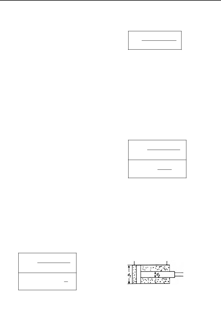
2. Piston speeds:
2.1 Forward stroke (working stroke):
Q
P
= Q
pi
A
pi
in cm
2
piston area during working stro-
ke
d
1
in cm diameter of the piston
d
2
in cm diameter of the differential pis-
ton
vol
ppi
A
pi1
2
1
pi1
10
ʌ
4
Q
v
A
d
A
K
Q
pi
in l/min actual piston inward oil flow
Q
p
in l/min actual pump outflow
K
ws
in m/min speed of piston on forward stroke
K
R
in m/min speed of piston on return stroke
K
pivol
– volumetric efficiency of piston
2.2 Return stroke:
vol
ppi
R
pi2
22
pi2
12
10
ʌ
()
4
Q
v
A
Add
K
A
pi
2
in cm
2
piston area on return stroke
Figure 26.3 Hydraulic cylinder with dif-
ferential piston

320 26 Hydraulic presses
3. Piston force (without considering piston own weight and friction)
3.1 Press force (working stroke)
pi1
2
10
pA
F
F in kN press force
p
in bar operating pressure (as N/cm
2
)
3.2 Ram retraction force
pi2
R
2
10
pA
F
F
R
in kN retraction force.
26.2 Example
A constant feed pump providing a feed flow of Q
p
= 200 l/min at an operating pressure of p =
150 bar is to be used to power a small hydraulic press.
Where:
diameter of the working piston d
1
= 200 mm;
diameter of the differential piston d
2
= 160 mm;
K
pi
vol
= 0.97
Find:
1.
press force
2. retraction force
½
¾ without considering own weight and friction
¿
3. speed of piston on forward stroke (operating speed)
4.
speed on return stroke.
Solution:
1.
2
pi1
def
222
150daN (20cm) ʌ
471.2 kN
10 N/ kN cm 10 N/ kN 4
pA
F
2.
22
22 22
12
R
222
()
150daN(20cm 16cm)ʌ
159 kN
10 4 cm 10 4
pd d
F
3.
vol
ppi
A
22
pi1
10
200 l 10 0.97
6.17 m/ min
min 20 cm ʌ /4
Q
v
A
K
4.
ppivol
R
22 22
pi2
10
200 l 10 0.97
17.1 m/ min
min (20 cm 16 cm ) ʌ /4
Q
v
A
K
.