Teodorescu P.P. Mechanical Systems, Classical Models Volume II: Mechanics of Discrete and Continuous Systems
Подождите немного. Документ загружается.

15 Dynamics of the Rigid Solid with a Fixed Point
where
ϕ
ω is the mean value of the proper rotation angular velocity, while
()tϕ
represents the oscillation of period
2K/p around the mean value
()
00
tt
ϕ
ϕω+−.
Starting from (15.1.59'), we can write
()
2
12 12
2
12
1tan
2
1tan
I
II II
II
ϕ
Ω
ψ
ϕ
−
⎡
⎤
=++−
⎢
⎥
+
⎣
⎦
()
() ()
() ()
22
00
12 12
22
12
00
cos sin
2
cos sin
ktt tt
I
II II
II
ktt tt
ϕϕ
ϕϕ
ωβω
Ω
ωβω
′
−− −
⎡⎤
=+−−
⎢⎥
′
−+ −
⎣⎦
()
12 12
22
12
4
()
2
Ikk
II II Rt
II k
k
Ωββ
β
β
′′
+
⎧⎫
⎡
⎤
=+−− −
⎨⎬
⎢
⎥
′
−
′
−
⎩⎭
⎣
⎦
,
in the frame of the order of approximation considered above; by integration, we obtain
the precession in the form
()
00
() ()tttt
ψ
ψψω ψ=+ − + ,
12
1 II
k
II
k
ψ
ωβΩ
β
⎡
⎤
′
=+
⎢
⎥
′
+
⎣
⎦
,
()
()
()
12
0
22
12
1
() 1 sin2
n
n
k
II I
k
tAntt
II
k
ϕ
ϕ
βΩ
ψω
ω
β
∞
=
′
−
=−−
′
−
∑
,
(15.1.62')
where
ψ
ω is the mean value of the angular velocity of precession, while
()tψ is the
oscillation of period
2K/p around the mean value
()
00
tt
ψ
ψω+−.
Noting that
()( )
0
31 1 3 33 0
//cosII I II I I IωΩ θ−−= =, corresponding to the
initial moment
0
t , the first formula (15.1.59'') and the last formula (15.1.60''') lead to
()
()
0
0
0
12cos2
cos cos
12cos2
qtt
k
qtt
ϕ
ϕ
ω
γθ θ
ω
+−
′
==
−−
,
where we have retained only the first power of
q in the expansion into series (15.1.60'), in
conformity to the notations (15.1.60''). Expanding the above ratio into a power series and
proceeding as in the preceding cases, we can represent the nutation in the form
0
cos ( ) ( )ttθγγ=+
,
()
2
00
14 cosqkγθ
′
=+
,
(15.1.62'')
() ()
21
00 0
1
( ) 4 cos 3 cos 2 cos2
n
n
t qk q tt q n tt
ϕϕ
γθω ω
∞
−
=
⎡
⎤
′
=−+−
⎢
⎥
⎣
⎦
∑
,
where
0
γ is a mean value, while ()tγ
represents the oscillation of period 2K/p
around this mean value.
313
MECHANICAL SYSTEMS, CLASSICAL MODELS
We have seen in Sect. 14.1.1.3 that the position of the rigid solid with respect to the
fixed frame of reference
′
R
can be specified also by means of the Cayley-Klein
parameters
α, β, γβ=− , δα= (the upperlining indicates the complex conjugate);
15.1.2.3 Geometric representation of the motion after Poinsot
Setting up the ellipsoid of inertia
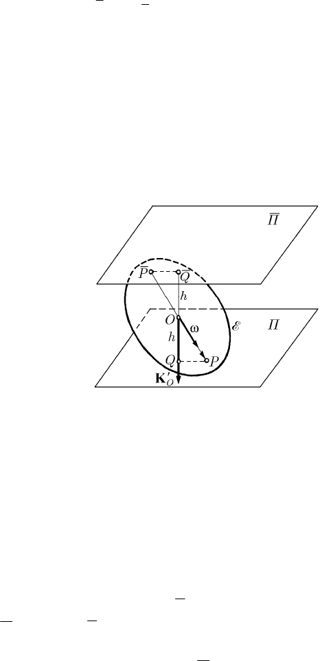
E (Poinsot’s ellipsoid) at the point O, one obtains a
geometric representation of the motion of the rigid solid with a fixed point; the position
vector of a point
P of the ellipsoid is situated along the angular velocity vector ω at this
point, being specified by the formula (15.1.15). The plane
Π tangent to the ellipsoid at
Fig. 15.7 The motion of rolling and pivoting without sliding of
Poinsot’s ellipsoid on one of Laplace’s planes
the point
P, called pole, is normal to the moment of momentum
O
′
K at the pole O. The
distance
||hOQ=
from the point O to this plane is given by (15.1.16), being constant
in time (Fig. 15.7) (these results hold for any motion of the rigid solid with a fixed point;
see Sect. 15.1.1.2 too). But, in the considered Euler-Poinsot case, the vector
O
′
K
is
constant in time with respect to the fixed frame of reference
′
R , so that the plane Π is
of constant normal, being situated at a constant distance from the point
O; hence, the
plane
Π is fixed with respect to the frame
′
R
. The instantaneous rotation axis pierces
Poinsot’s ellipsoid at a second point
P
and the support of
O
′
K is normal also to the
plane
Π tangent at P to the ellipsoid. Projecting the constant vector
O
′
K on the
normal to a given plane, one obtains a constant; the planes parallel to this plane are
called Laplace planes. The planes
Π and Π belong to a family of invariable planes of
Laplace. The point
P of contact is on the instantaneous axis of rotation, having thus a
null velocity; we can state
F. Klein showed that in the Euler-Poinsot case these parameters are elliptic functions
of second kind which, both at the numerator and at the denominator, have only one
theta function.
314

15 Dynamics of the Rigid Solid with a Fixed Point
Theorem 15.1.9 (Poinsot) In the Euler-Poinsot case, the rigid solid with a fixed point
is moving so that Poinsot’s ellipsoid
E corresponding to the fixed point has a
slidingless rolling and pivoting motion on one of Laplace’s planes. The magnitude
ω of
the rotation instantaneous angular velocity is in direct proportion to the magnitude of
the position vector of the point
P at which the instantaneous axis of rotation pierces the
ellipsoid.
We can express the distance
h also in the remarkable form
0
KK
h
J
I
==
,
(15.1.16')
which allows an interesting interpretation of the constant
I; as well, we have
()
vers
2cos,
O
Ih h
OP h
T
Ω
===
′′
K
ωω ω
ω
.
(15.1.15')
Because
||OP
is contained between the semi-minor axis
1
/KI
and the semi-major
axis
3
/KI, we get
()
2
31
cos ,
O
II I I
Δ
′
<= <
K ω , justifying once more the
inequality
3
II≥ . On the other hand, ||hOP≤
and
1
/hK I≥ (because the point
Q is exterior to the ellipsoid or at the most on it), so that
13
///KI KIKI≤≤ ; finally, it results
31
III≤≤.
We have used, in the above exposition, the ellipsoid of inertia
E, represented with
respect to the principal axes of inertia taken as axes of the non-inertial frame of
reference
R in the form
22222
11 22 33
Ix Ix Ix K Ih++==,
(15.1.63)
where
0K > is a constant which specifies the units (K has the dimensional equation
[]
1/2 2
KML= ) and is conveniently determined (see Chap. 3, Sect. 1.2.6 too). Giving
various values to the constant
K, one can use different ellipsoids of Poinsot; for
instance, one can take
1K = (in this case, the unit has dimension), the respective
ellipsoid being obtained from (15.1.63) by a similitude with the ratio
K . One can use
also the second equation (15.1.47), with
22
KIΩ=
; in this case, the position vector of
the pole
P is just ω. The equation of the tangent plane to the ellipsoid E at the pole P
(
/2
i
KTω
′
,
1,2, 3i =
) is given by
111 222 333
2Ix Ix I x KT K IIhωω ω ΩΩ
′
++= = =
,
(15.1.63')
where
123
,,xxx are the co-ordinates of a point of the Π-plane.
315
MECHANICAL SYSTEMS, CLASSICAL MODELS
Starting from the ellipsoid of gyration
′
E (the ellipsoid reciprocal to the ellipsoid of
inertia), introduced in Chap. 3, Sect. 1.2.6 and used in Sect. 14.1.1.6, J. Mac Cullagh
succeeded to give, in 1840, another intuitive image of the motion of the rigid solid with
a fixed point. We will use the equation (3.1.105) of the ellipsoid of gyration, with
respect to the principal axes of inertia, in the movable frame of reference
R, in the
form
222
123
123
1
xxx
IIIM
++=
,
(15.1.64)
where we take
2
KRM= (a point P
′
∈
′
E is the inverse of the point Q Π∈ from
the preceding subsection, with respect to the sphere
()
,OR ); we put thus in evidence
the principal moments of inertia, which is more convenient in the following
calculations.
Noting that
11
1
O
KIω
′
=
,
22
2
O
KIω
′
=
,
33
3
O
KIω
′
=
, the equations of the support
D of the vector
O
′
K , fixed with respect to the frame of reference
′
R , are
222
123 123
22 22 22
11 22 33
11 22 33
x x x xxx
III
III
ωωω
ωωω
++
===
++
.
(15.1.65)
Assuming that
K
i
x , 1,2, 3i = , are the co-ordinates of one of the points
K
P
′
,
K
P
′
≡∩
′
DE
and eliminating these co-ordinates between the equations (15.1.64),
(15.1.65), we obtain
222
2
11 22 33
22 22 22
11 22 33
1
K
III
OP
M
III
ωωω
ωωω
++
′
=
++
,
wherefrom
||
O
K
J
I
OP i
M
M
′
===
,
(15.1.65')
i being a constant quantity of the nature of a radius of gyration, corresponding to the
constant quantity
I. We notice that ||
K
OP
′
is contained between the semi-minor axis
and the semi-major axis of the ellipsoid
′
E
, so that
31
iii≤≤
(so as
31
III≤≤
),
justifying thus once more both inequalities established before. Hence, the points
K
P
′
and
K
P
′
, situated on the invariable axis D and diametrically opposed in the ellipsoid of
gyration
′
E
, are fixed with respect to the frame of reference
′
R
(
||||const
KK
OP OP
′′
==
) (Fig. 15.8); to fix the ideas, the position vector of the point
K
P
′
will be /
O
JM, of components
111
/
K
OO
xJI KMω
′
=
,
15.1.2.4 Geometric representation of the motion after Mac Cullagh
316
15 Dynamics of the Rigid Solid with a Fixed Point
222
/
K
OO
xJI KMω
′
=
,
333
/
K
OO
xJI KMω
′
=
. The equation of the plane Π
′
,
tangent to the ellipsoid
′
E
at the point
K
P
′
, is given by
11 22 33
O
O
K
xxx
JM
ωωω
′
++=
,
(15.1.64')
the normal
OQ
′
to this plane having the direction parameters
i
ω ,
1,2, 3i =
; hence,
the angular velocity vector
ω is normal to this plane. Moreover, the distance h
′
from
the point
O to this plane is given by
222
123
OO
O
O
KK
h
JM
JM
ω
ωωω
′′
′
==
++
.
(15.1.64'')
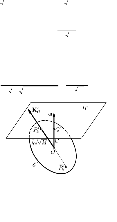
Fig. 15.8 The inertial motion of the rigid solid with a fixed point
in Mac Cullagh’s geometric representation
Hence, we can state
Theorem 15.1.10 (J. Mac Cullagh) The inertial motion of a rigid solid about a fixed
point
O of it, in the Euler-Poinsot case, takes place so that the ellipsoid of gyration
′
E
corresponding to this point passes through the fixed points
K
P
′
and
K
P
′
, situated on the
invariable axis
D. The rotation angular velocity ω is normal to the plane tangent to the
ellipsoid of gyration
′
E
at one of the fixed points, while its magnitude ω is in inverse
proportion to the distance
h
′
from the fixed point O to the plane Π
′
.
15.1.2.5 The Polhode
The locus of the point
P at which the instantaneous axis of rotation pierces the ellipsoid
of inertia
E (rigidly linked to the rigid solid S ) is a curve P called polhode,
intersection of the ellipsoid with the polhodic cone
p
C (the locus of the instantaneous
axes of rotation with respect to the frame of reference
R ), hence a directrix of this
cone. Analogously, the locus of the point
P on the fixed plane Π, tangent to the
317
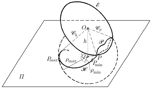
MECHANICAL SYSTEMS, CLASSICAL MODELS
ellipsoid
E at this point, is a curve H, called herpolhode, intersection of the plane Π
with the herpolhodic cone
h
C (the locus of the instantaneous axes of rotation with
respect to the frame
′
R
) (in Fig. 15.9 we represent the polhode and the herpolhode
corresponding to the point
P and the plane Π; for the point P
′
and the plane Π
′
one
obtains analogous results). Obviously, the two curves are tangent one to the other,
measuring equal lengths between corresponding points, because of the slidingless
rolling of the polhodic cone over the herpolhodic one (and of the polhode over the
herpolhode).
Fig. 15.9 The polhode P and the herpolhode H in the motion
of a rigid solid with a fixed point
If we eliminate
2
Ω between the first integrals (15.1.47), then we find
() () ()
222
11 1 22 2 33 3
0II I II I II Iωωω−+ −+ −=.
(15.1.66)
Assuming that
123
III>>, one cannot have
1
II> or
3
II< , because the left
member would be strictly negative or strictly positive, the cone being imaginary; hence,
31
III≤≤, result previously obtained. Taking into account (15.1.15'), the equation of
the instantaneous axis is written in the form
11 22 33
////xxxhωωωΩ=== in the
frame of reference
R, the equation of the polhodic cone ( in the same frame) being
() () ()
222
11 1 22 2 33 3
0I I Ix I I Ix I I Ix−+ −+ −=.
(15.1.66')
Because
p
P ≡∩EC, the polhode will have the equations (15.1.63), (15.1.66); hence,
this is an algebraic curve of the fourth degree with two distinct closed branches and
with properties of central symmetry (with respect to the co-ordinate planes too), the
polhodic cone having the same axes of symmetry as the ellipsoid
E. Multiplying the
equation (15.1.63) by
I and summing with the equation (15.1.66'), we obtain the
equation of an ellipsoid
k
E , called kinetic ellipsoid (due to the signification of the first
integral (15.1.47)),
318
15 Dynamics of the Rigid Solid with a Fixed Point
22 22 22 22 2
11 22 33
Ix Ix Ix Ih IK++==.
(15.1.67)
The ellipsoid
k
E is coaxial with the ellipsoid E, the two ellipsoids having as
intersection the polhodic curve.
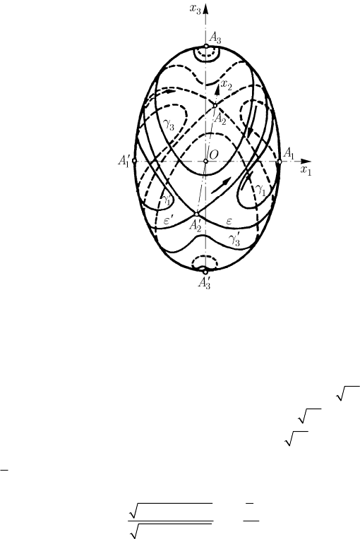
Fig. 15.10 Polhodes drawn on the ellipsoid of inertia E
Concerning the polhodic cone, we notice that the first coefficient of the equation
(15.1.66) is always positive, while the last one is always negative; in what concerns the
second coefficient, this one is positive or negative as
2
II< or
2
II> , respectively,
depending thus on the initial conditions. In the first case,
2
hKI> and the polhodic
cone contains the
3
Ox
-axis; in the second case,
2
hKI< and the polhodic cone
contains the
1
Ox -axis. If
2
II= , hence if
2
/hK I=
, then the polhodic cone
degenerates in two planes (we use the notations (14.1.49') and notice that
22
ββΩ==)
()
()
32 3 1
13 3
3
11 2
II I
xx x
II I
β
β
−
=± =±
−
,
(15.1.68)
which pass through the mean axis (the axis
22
AA
′
) of the ellipsoid E, the corresponding
polhode being constituted of two ellipses (
ε and ε
′
) for which this axis is a common
one (Fig. 15.10) (the only case in which the two branches of the polhode have common
points). If
1
II= or
3
II= we have
23
0xx== or
12
0xx==, respectively, the
polhode being reduced to the points
1
A and
1
A
′
(extremities of the minor axis of the
ellipsoid) or to the points
3
A and
3
A
′
(extremities of the major axis of the ellipsoid),
respectively. If
21
III<<, then the polhode is formed of two closed curves
1
γ and
319

MECHANICAL SYSTEMS, CLASSICAL MODELS
1
γ
′
, which surround the points
1
A and
1
A
′
, respectively; as well, if
32
III<<, then
the polhode is formed of two closed curves
3
γ and
3
γ
′
, which surround the points
3
A
and
3
A
′
, respectively (Fig. 15.10). In the hypothesis considered in Sect. 15.1.2.1
(
()
0
20 2
0tωω=>,
()
10
0tω < ,
()
30
0tω > ), the pole P travels through the
polhodes in the sense indicated in Fig. 15.10 (on the curves on which the sense has not
been indicated, that one is obtained by symmetry). To have a clearer image of the
polhode, we consider also its projection on the three planes of co-ordinates, in the frame
of reference
R. Thus, projecting on the plane
12
Ox x (we eliminate
3
x between the
equations (15.1.63) and (15.1.66')) for various values of
I (hence, for various initial
conditions), we obtain a family of coaxial ellipses of equations (cylinders of elliptic
section which pierce the ellipsoid of inertia after polhodes)
()()()
222
11 31 22 33 3
II Ix II Ix II Ih−+−=−.
Taking into account the notations (15.1.49), (15.1.49'), we can write these equations
also in the form
22
22
12
22 2 2
12
xx
hK
I
ββΩ Ω
+= = .
(15.1.68')
Moreover, starting from the first equation (15.1.49'') and using the relation (15.1.15'),
we find again these equations, the respective ellipses being equivalent. We notice that
for
2
II> one obtains arcs of ellipse, bounded by the ellipse of inertia
222
11 22
Ix Ix K+=, while for
2
II≤ there result complete ellipses (Fig. 15.11a).
Projecting the polhode on the plane
23
Ox x (we eliminate
1
x between the equations
(15.1.63) and (15.1.66')) and using the same notations, we get – analogously – a family
of coaxial ellipses (cylinders of elliptic section, which pierce the ellipsoid of inertia
after polhodes)
22
22
23
22 2 2
23
xx
hK
I
ββΩ Ω
+= = .
(15.1.68'')
Taking into account the relation (15.1.15'), one observes that these ellipses are
equivalent with the second ellipse (15.1.49''). For
2
II< there result arcs of ellipse,
bounded by the ellipse of inertia
222
22 33
Ix Ix K+=, while for
2
II≥ there result
complete ellipses (Fig. 15.11b). Finally, the projection of the polhode on the plane
31
Ox x (one eliminates
2
x between the equations (15.1.63) and (15.1.66')), with the
same notations, leads to two conjugate coaxial hyperbolae (cylinders of hyperbolic
section, the traces of which on the ellipsoid of inertia are the polhodes)
22
22
31
22 2 2
1
3
xx
hK
I
βΩ Ω
β
−= = ,
(15.1.68''')
320
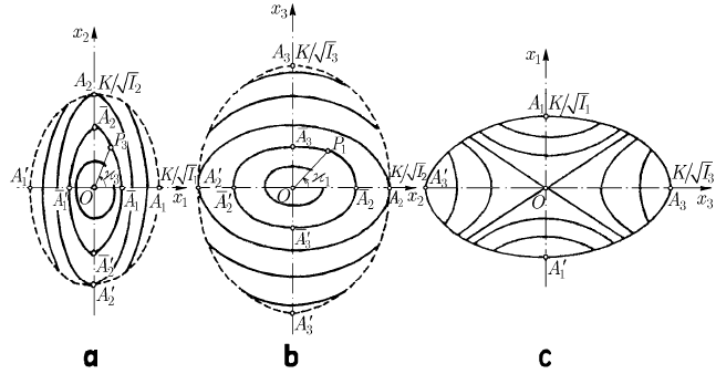
15 Dynamics of the Rigid Solid with a Fixed Point
which degenerate in two straight lines, specified by the equations (15.1.68), for
2
II= .
If
2
II< , then the polhode is formed of two arcs of hyperbola, the real axis of which is
the axis
11
AA
′
(Fig. 15.11c). Taking into account the relation (15.1.15'), one observes
that these hyperbolae are equivalent to the hyperbola (15.1.49''').
Fig. 15.11 Projections of a polhode on the planes
12
Ox x (a),
23
Ox x (b) and
31
Ox x (c)
Concluding, there are two families of polhodes, separated by the singular polhode
corresponding to the case
2
II= (ε and ε
′
); a family of polhodes (
1
γ and
1
γ
′
)
surround the extremities of the minor axis of the ellipsoid of inertia, while the other
family of polhodes (
3
γ and
3
γ
′
) surround the extremities of the major axis of this
ellipsoid. Through each point of the ellipsoid passes a polhode and only one. The
polhodes being plotted on the ellipsoid, to can determine that one which corresponds to
given initial conditions it is sufficient to know the piercing point
0
P of the support of
the angular velocity vector
ω on the ellipsoid of inertia at the initial moment; the
searched polhode is that which passes through
0
P , while the plane tangent to the
ellipsoid at
0
P is the plane Π.
15.1.2.6 The Herpolhode
Studies to determine the herpolhode have been made by W. Hess, Sparre, G. Darboux,
A.G. Greenhill, G. Halphen, J.N. Franke, A. Mannheim, A. de St. Germain, A.H. Résal,
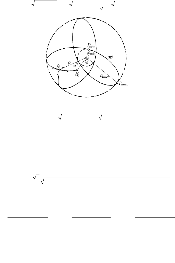
P. Barbarin, E. Lacour, A. Petrus etc. In what follows, we use polar co-ordinates in the
plane
Π, taking as pole of reference the point Q, projection of the fixed point O on the
fixed plane
Π (Fig. 15.9). The vector radius is given by
321
MECHANICAL SYSTEMS, CLASSICAL MODELS
2
222 22
hK
QP OP h
I
ρωΩωΩ
Ω
Ω
== − = − = − .
(15.1.69)
Fig. 15.12 The herpolhode drawn in a circular annulus
Taking into account that
13
/||/KI OPKI≤ ≤
, it results that ρ is inferior and
superior bounded, so that the herpolhode is a curve contained in a circular annulus
C
(
max
min
ρρρ≤≤ ) (Fig. 15.12). We get
2
22 2
2
I
K
ρ
ωΩ Ω
=+
(15.1.69')
from (15.1.69), while by replacing in (15.1.57') we may write
()
()
[]
()
()
[]
2
22 2222
12 2 3 2
d
2 sign sign
d
I
II II
tK
ρ
Ω
ρδ δρρδ
=± − − − − − ,
(15.1.70)
where we have introduced the notations
()
23
22
1
23
||IIII
K
III
δ
−−
=
,
()()
31
22
2
31
II I I
K
III
δ
−−
=
,
()
12
2
3
12
||IIII
III
δ
−−
=
.
(15.1.70')
If
2
II< , then we have
min 1
ρδ= , while if
2
II> , then we have
min 3
ρδ= ; in both
cases,
max
2
ρδ= . Integrating the differential equation (15.1.70), one can express the
vector radius
ρ by means of elliptic functions.
We get the same result noting that
2
2 2 2222
123
OPhxxxhρ = −=++−; using the
equations of the cylinders (15.1.68')–(15.1.68''') and eliminating the variables
2
x and
3
x or the variables
1
x and
2
x , we obtain
322
