Szilas A.P. Production and transport of oil and gas, Gathering and Transportation
Подождите немного. Документ загружается.

80 6.
GATHERING AND SEPARATION
OF,
OIL
AND GAS
vortex still containing mist rises through tube
5
above baffle
4.
The least-pressure
point of the vortex is above the central orifice
in
plate
4.
Some
of
the mist particles
in
the gas impinge upon the lower surface
of
bell
2
and, coalescing, drip down into the
liquid space. Most
of
the mist rising in tube
5
is thrown by vortex motion against the
inner tube wall. Suction from the low-pressure centre generated above plate
4
sucks
Fig.
6.4
-
3
I.
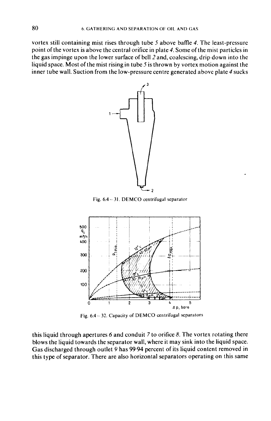
DEMCO centrifugal separator
A
p,
bar6
Fig.
6.4-
32.
Capacity
of
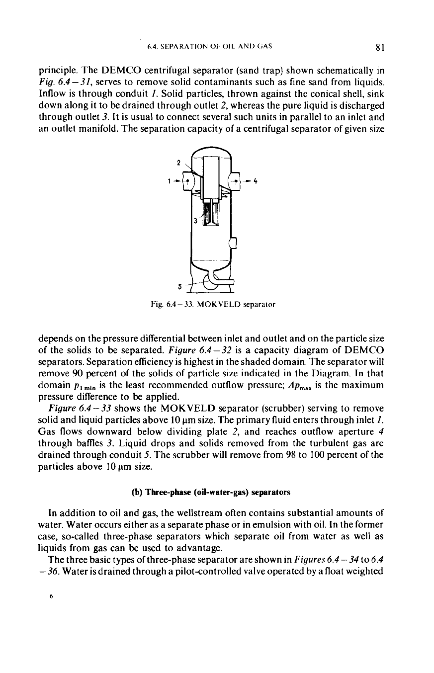
DEMCO centrifugal separators
this liquid through apertures
6
and conduit
7
to orifice
8.
The vortex rotating there
blows the liquid towards the separator wall, where
it
may sink into the liquid space.
Gas discharged through outlet
9
has
99.94
percent
of
its liquid content removed
in
this type
of
separator. There are also horizontal separators operating on this same
6.4.
SEPARATION
OF
011.
AND (;AS
81
principle. The DEMCO centrifugal separator (sand trap) shown schematically
in
Fig.
6.4-31,
serves
to
remove solid contaminants such as fine sand from liquids.
Inflow is through conduit
1.
Solid particles, thrown against the conical shell, sink
down along it to be drained through outlet
2,
whereas the pure liquid is discharged
through outlet
3.
It is usual to connect several such units in parallel to an inlet and
an outlet manifold. The separation capacity
of
a centrifugal separator
of
given size
Fig.
6.4-
33.
MOKVELD
separator
depends on the pressure differential between inlet and outlet and on the particle size
of
the solids to
be
separated.
Figure
6.4-32
is a capacity diagram
of
DEMCO
separators. Separation efficiency is highest
in
the shaded domain. The separator will
remove
90
percent
of
the solids
of
particle size indicated in the Diagram.
In
that
domain
p1
is the least recommended outflow pressure;
dp,,,
is
the maximum
pressure difference
to
be applied.
Figure
6.4-33
shows the MOKVELD separator (scrubber) serving to remove
solid and liquid particles above
10
pm size. The primary fluid enters through inlet
1.
Gas flows downward below dividing plate
2,
and reaches outflow aperture
4
through bames
3.
Liquid drops and solids removed from the turbulent gas are
drained through conduit
5.
The scrubber will remove from
98
to
100
percent
of
the
particles above
10
pm
size.
(b)
Three-phase (oil-water-gas) separators
In addition to oil and gas, the wellstream often contains substantial amounts
of
water. Water occurs either as a separate phase
or
in emulsion with oil. In the former
case, so-called three-phase separators which separate oil from water as well as
liquids from gas can be used to advantage.
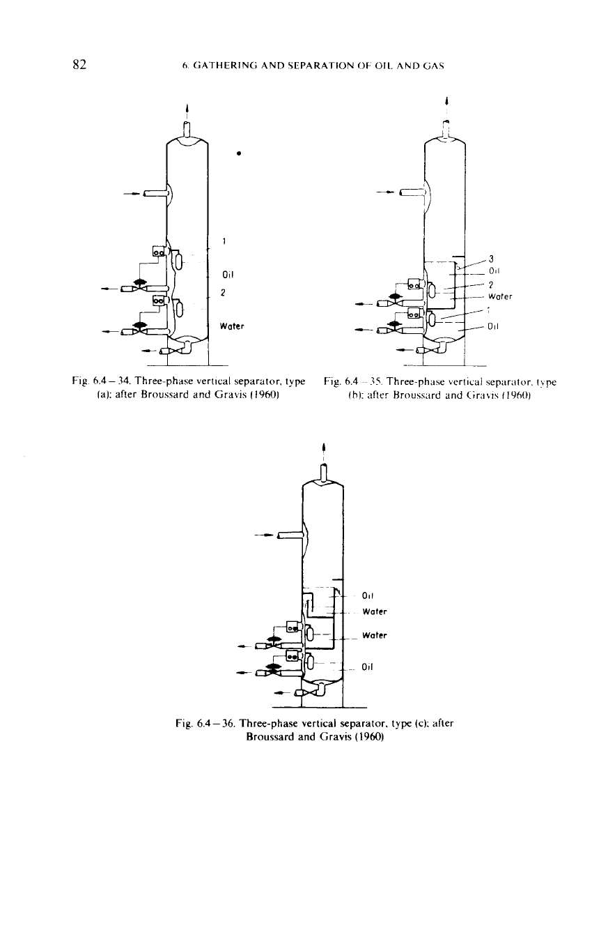
The three basic types
of
three-phase separator are shown in
Figures
6.4
-
34
to
6.4
-36.
Water is drained through a pilot-controlled valve operated by a float weighted
6
82
h
GATHERING AND 5LPARATlOhl
OF
011
AND
GA\
F
F
1
011
2
Water
6.4
-
34.
Three-phase vertical separator.
type
la): after Broussard and Gravis
(19601
Fig.
6.4
~~
35.
Three-phase vertical sepnrator.
t!pe
fb):
after Hroussard and
C;r:i\i?
f
1960)
Fig.
6.4
-
36.
Three-phase vertical separator. type
(c):
after
Broussard
and
Gravis
(1960)
64
SFPARATION
OF
011
AND GAS
83
so
as to float at the water-oil interface.
In
type (a), oil and water levels are maintained
by floats
1
and
2
alone. The gravity difference between water and oil is usually rather
slight, and
so
is the differential buoyancy maintaining the weighted float at the
water-oil interface. Sudden slugs of incoming liquid may make the floats bob up and
down, which is detrimental to accurate level maintenance. This type is com-
paratively cheap and simple; the entire bottom space is available for settling; sand
and mud deposits are comparatively easy
to remove. In type (b) floats
I
and
2
are
assisted
in
maintaining liquid levels by weir
3.
Settling space is, however, less than in
type (a), and the internal fittings tend to hamper cleaning. In design (c), two separate
liquid levels are maintained by weirs and floats, and there is no interface float. Water
and oil collect in separate compartments. This has the advantage that, should any
one of the float-operated level controls fail, water and oil will discharge separately,
even though both
will
be mixed with gas. Its drawback is that the settling space is
even smaller than
in
type (b). cleaning is cumbersome, and the entire device is rather
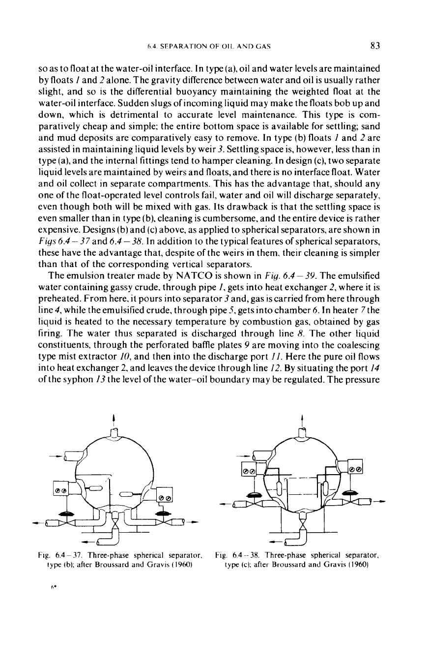
expensive. Designs (b) and (c) above,
as applied to spherical separators, are shown in
Figs
6.4
-
37
and
6.4
-
38.
In
addition to the typical features of spherical separators,
these have the advantage that, despite of the weirs in them. their cleaning is simpler
than that of the corresponding vertical separators.
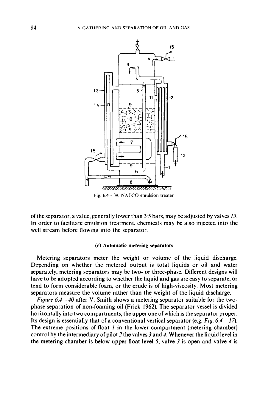
The emulsion treater made by NATCO is shown
in
Fig.
6.4
-
3Y.
The emulsified
water containing gassy crude, through pipe
1,
gets into heat exchanger
2,
where
it
is
preheated. From here.
it
pours into separator
3
and, gas is carried from here through
line
4,
while the emulsified crude, through pipe
5,
gets into chamber
6.
In
heater
7
the
liquid is heated
to
the necessary temperature by combustion gas. obtained by gas
firing. The water thus separated is discharged through line
8.
The other liquid
constituents, through the perforated bame plates
9
are moving into the coalescing
type mist extractor
10,
and then into the discharge port
1 1.
Here the pure oil flows
into heat exchanger
2,
and leaves the device through line 12. By situating the port
14
of the syphon
13
the level
of
the water-oil boundary may be regulated. The pressure
I
r4
-“I“_
‘---I-
-
t
c
Fig.
6.4
-
37.
Three-phase spherical separator,
Fig.
6.4
--
38.
Three-phase spherical separator.
type
Ib);
after Broussard and Gravis
(19601
type (c): after Broussard and Gravis
(1960)
84
6.
GATHERING AND SEPARATION
OF
OIL
AND GAS
I,
r?
I
"m
'I
Fig.
6.4
-
39.
NATCO
emulsion treater
of the separator, a value, generally lower than
3.5
bars, may
be
adjusted by valves
15.
In order to facilitate emulsion treatment. chemicals may be also injected into the
well stream before flowing into the separator.
(c)
Automatic metering separators
Metering separators meter the weight
or
volume of the liquid discharge.
Depending on whether the metered output is total liquids
or
oil and water
separately, metering separators may be two-
or
three-phase. Different designs will
have
to
be
adopted according to whether the liquid and gas are easy to separate,
or
tend to form considerable foam,
or
the crude is
of
high-viscosity. Most metering
separators measure the volume rather than the weight of the liquid discharge.
Figure
6.4-40
after
V.
Smith shows a metering separator suitable for the two-
phase separation of non-foaming
oil
(Frick
1962).
The separator vessel is divided
horizontally into two compartments, the upper one
of
which is the separator proper.
Its design is essentially that of a conventional vertical separator (e.g.
Fig.
6.4
-
17).
The extreme positions
of
float
I
in the lower compartment (metering chamber)
control by the intermediary of pilot
2
the valves
3
and
4.
Whenever the liquid level in
the metering chamber is below upper float level
5,
valve
3
is open and valve
4
is
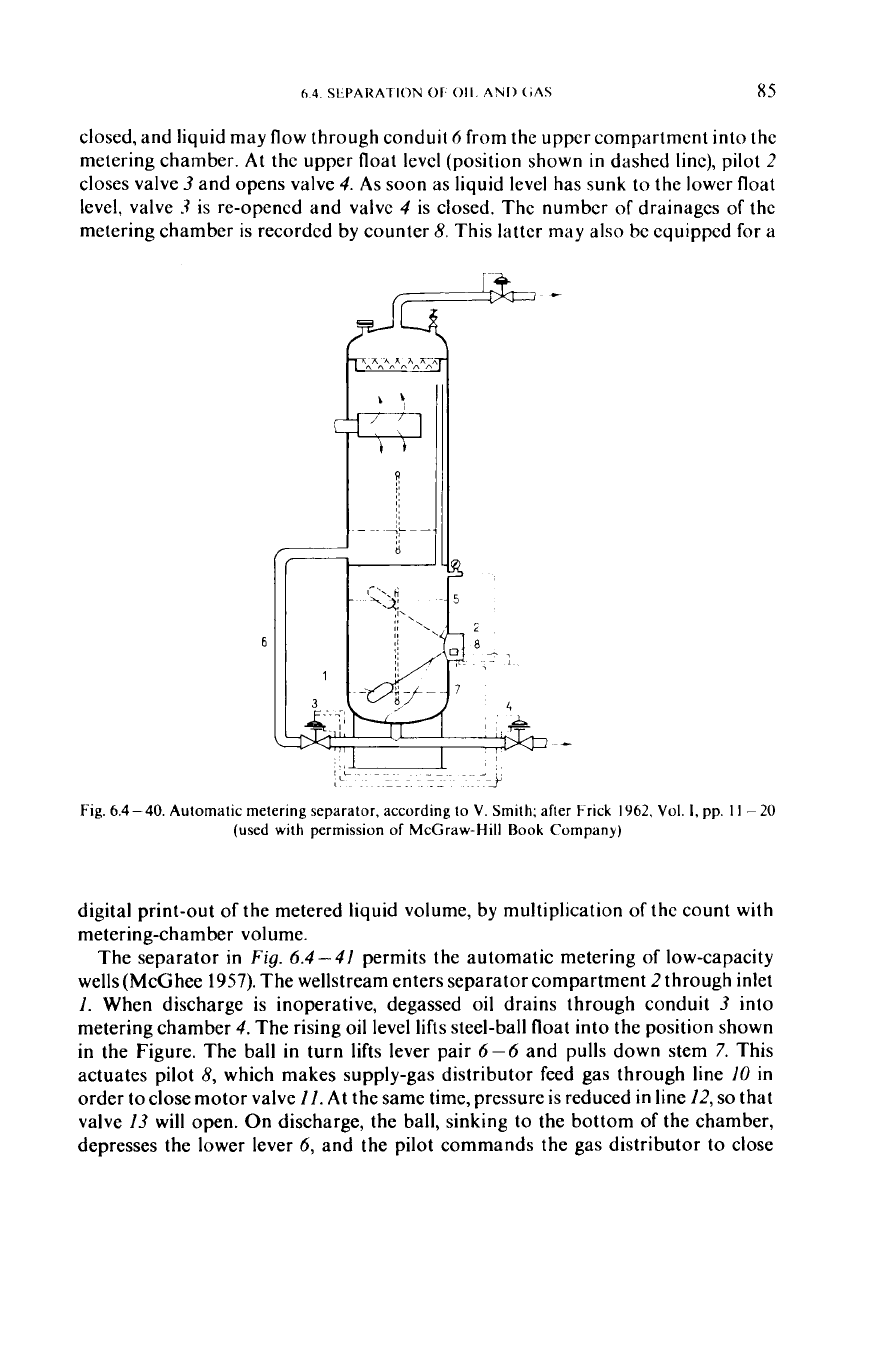
closed, and liquid may flow through conduit
6
from the upper compartment into the
metering chamber.
At
the upper float level (position shown
in
dashed line), pilot
2
closes valve
3
and opens valve
4.
As soon as liquid level has sunk to the lower float
level, valve
3
is re-opened and valve
4
is closed. The number of drainages of the
metering chamber
is
recorded by counter
8.
This latter may also bc equipped for a
Fig.
6.4-40.
Automatic metering separator, according
to
V.
Smith: after Frick
1962.
Vol.
I,
pp.
11
-
(used
with permission
of
McGraw-Hill
Rook
Company)
20
digital print-out of the metered liquid volume, by multiplication of the count
with
metering-chamber volume.
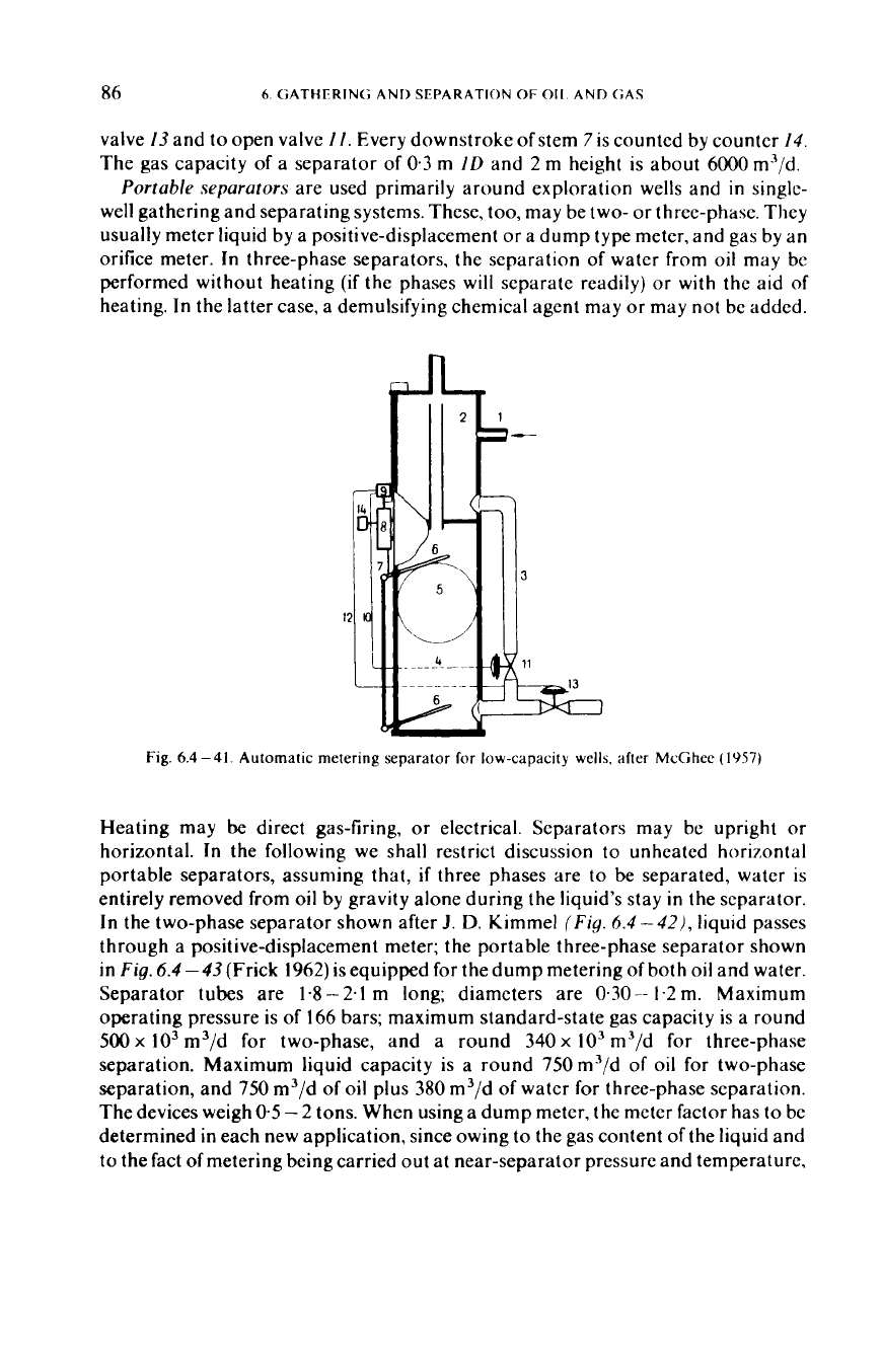
The separator in
Fig.
6.4-41
permits the automatic metering of low-capacity
wells (McGhee
1957).
The wellstream enters separator compartment
2
through inlet
1.
When discharge is inoperative, degassed oil drains through conduit
3
into
metering chamber
4.
The rising oil level lifts steel-ball float into the position shown
in the Figure. The ball
in
turn lifts lever pair 6-6 and pulls down stem
7.
This
actuates pilot
8,
which makes supply-gas distributor feed gas through line
10
in
order
to
close motor valve
11.
At the same time, pressure is reduced in line
12,
so
that
valve
13
will open. On discharge, the ball, sinking to the bottom of the chamber,
depresses the lower lever
6,
and the pilot commands the gas distributor to close
86
6.
GATHERIN(; AND SEPARATION
OF
011.
AND <;AS
valve
13
and to open valve
11.
Every downstroke of stem
7
is counted by counter
14.
The gas capacity of a separator of
0.3
m
ID
and
2
m height is about
6000
m3/d.
P
ortab/e separators
are used primarily around exploration wells and in single-
well gathering and separating systems. These, too, may be two-
or
three-phase. They
usually meter liquid by a positive-displacement
or
a dump type meter, and gas by an
orifice meter.
In
three-phase separators, the separation of water from oil may
bc
performed without heating
(if
the phases will separate readily)
or
with
the aid of
heating. In the latter case, a demulsifying chemical agent may
or
may not be added.
Fig.
6.4 -41. Automatic metering separator
for
low-capacity wells. after
McGhee
(1957)
Heating may be direct gas-firing,
or
electrical. Separators may be upright
or
horizontal. In the following we shall restrict discussion to unheated horizontal
portable separators, assuming that,
if
three phases are to be separated, water is
entirely removed from
oil
by gravity alone during the liquid’s stay
in
the separator.
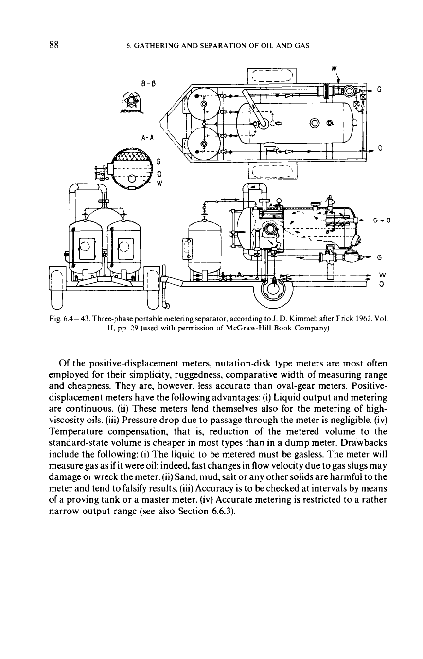
In the two-phase separator shown after
J.
D.
Kimmel
(Fig.
6.4-42),
liquid passes
through a positive-displacement meter; the portable three-phase separator shown
in
Fig.
6.4
-
43
(Frick
1962)
is equipped for the dump metering of both oil and water.
Separator tubes are
1.8-2.1
m long; diameters are
0.30--
1-2m. Maximum
operating pressure is of
166
bars; maximum standard-state gas capacity is a round
500
x
lo3
m3/d for two-phase, and a round
340
x
lo3
m3/d for three-phase
separation. Maximum liquid capacity is a round 750m3/d of oil for two-phase
separation, and
750
m3/d of oil
plus
380
m3/d of water for three-phase separation.
The devices weigh
0.5
-
2
tons. When using a dump meter, the meter factor has to be
determined in each new application, since owing to the gas content of the liquid and
to the fact
of
metering being carried out at near-separator pressure and temperature,
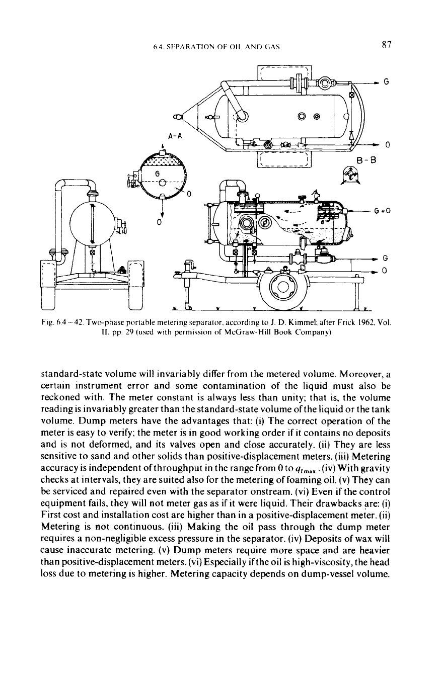
Fig.
6.4-42.
Two-phase portable metering separator. according
to
J.
D.
Kimmel; after
Frick
1962,
Vol.
11,
pp.
29
(used with permission
of
McGraw-Hill
Book
Company)
standard-state volume
will
invariably differ from the metered volume. Moreover, a
certain instrument error and some contamination of the liquid must also be
reckoned with. The meter constant is always less than unity; that is, the volume
reading is invariably greater than the standard-state volume of the liquid
or
the tank
volume. Dump meters have the advantages that:
(i)
The correct operation of the
meter is easy to verify; the meter is in good working order
if
it
contains no deposits
and is not deformed, and its valves open and close accurately.
(ii)
They are less
sensitive
to
sand and other solids than positive-displacement meters.
(iii)
Metering
accuracy is independent of throughput
in
the range from
0
to
qlmax .
(iv)
With gravity
checks at intervals, they are suited also for the metering
of
foaming oil.
(v)
They can
be
serviced and repaired even with the separator onstream.
(vi)
Even
if
the control
equipment fails, they will not meter gas as
if
it
were liquid. Their drawbacks are:
(i)
First cost and installation cost are higher than in a positive-displacement meter.
(ii)
Metering is not continuous.
(iii)
Making the oil pass through the dump meter
requires a non-negligible excess pressure in the separator.
(iv)
Deposits of wax will
cause inaccurate metering.
(v)
Dump meters require more space and are heavier
than positive-displacement meters. (vi) Especially
if
the oil is high-viscosity, the head
loss
due to metering
is
higher. Metering capacity depends on dump-vessel volume.
88
6.
GATHERING AND SEPARATION
OF
OIL
AND GAS
W
\
/-
--
--
Fig.
6.4-43. Three-phase portable metering separator, according
to
J.
D.
Kimmel; after Frick 1962, Vol.
11,
pp. 29 (used with permission of McGraw-Hill
Book
Company)
Of
the positive-displacement meters, nutation-disk type meters are most often
employed for their simplicity, ruggedness, comparative width of measuring range
and cheapness. They are, however, less accurate than oval-gear meters. Positive-
displacement meters have the following advantages:
(i)
Liquid output and metering
are continuous.
(ii)
These meters lend themselves also for the metering of high-
viscosity oils. (iii) Pressure drop due to passage through the meter is negligible.
(iv)
Temperature compensation, that is, reduction of the metered volume to the
standard-state volume is cheaper in most types than in a dump meter. Drawbacks
include the following:
(i)
The liquid to be metered must be gasless. The meter will
measure gas as
if
it were oil: indeed, fast changes in flow velocity due to gas slugs may
damage
or
wreck the meter.
(ii)
Sand, mud, salt
or
any other solids are harmful to the
meter and tend to falsify results. (iii) Accuracy is
to
be checked at intervals by means
of a proving tank
or
a master meter. (iv) Accurate metering is restricted to a rather
narrow output range (see also Section
6.6.3).
6.4
SEPARATION
OF
OIL
AND
GAS
89
6.4.6.
Low-temperature separation
If
the wellstream is cooled to a low temperature before entry into the separator,
separation will produce dry gas and a liquid rich in low-boiling-point hydrocarbons
(condensate). The dew point of dry gas is lower, which makes
it
better suited for
transportation in pipelines.
If
the liquid in the wellstream is
of
low boiling point
in
its entirety, then the liquid recovered will be raw gasoline rich in propane and
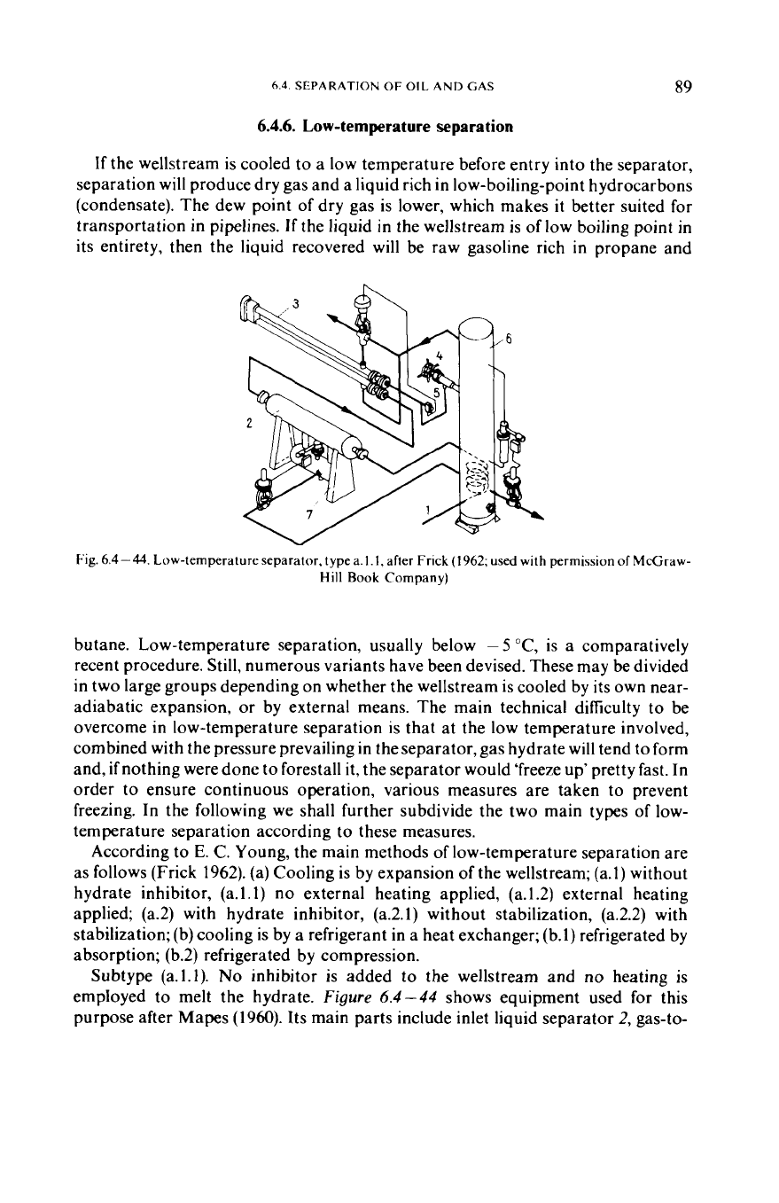
Fig.
6.4-44.
Low-temperatureseparator. typea.l.l,after Frick(1962; used
with
permissionofMcGraw-
Hill Book
Company)
butane. Low-temperature separation, usually below
-
5
"C,
is a comparatively
recent procedure. Still, numerous variants have been devised. These may be divided
in two large groups depending on whether the wellstream is cooled by its own near-
adiabatic expansion,
or
by external means. The main technical difficulty to be
overcome in low-temperature separation is that at the low temperature involved,
combined with the pressure prevailing in the separator, gas hydrate will tend to form
and,
if
nothing were done to forestall it, the separator would 'freeze up' pretty fast. In
order to ensure continuous operation, various measures are taken to prevent
freezing. In the following we shall further subdivide the two main types of low-
temperature separation according
to these measures.
According to
E.
C. Young, the main methods of low-temperature separation are
as follows (Frick 1962). (a) Cooling is by expansion of the wellstream; (a.1) without
hydrate inhibitor, (a.l.1) no external heating applied, (a.1.2) external heating
applied; (a.2) with hydrate inhibitor, (a.2.1) without stabilization, (a.2.2) with
stabilization; (b) cooling is by a refrigerant in a heat exchanger; (b.1) refrigerated by
absorption; (b.2) refrigerated by compression.
Subtype (a.l.1).
No
inhibitor is added
to
the wellstream and
no
heating is
employed to melt the hydrate.
Figure
6.4-44
shows equipment used for this
purpose after Mapes (1960). Its main parts include inlet liquid separator
2,
gas-to-