Szilas A.P. Production and transport of oil and gas, Gathering and Transportation
Подождите немного. Документ загружается.

I10
h
GATHERING
AND
SEPARATIOW
OF.
OIL
AND
GAS
p), while for the calculation of standard volumetric flow rate,
q,
,four
(pl
,
Ap,
M
and
3.
This is one reason of spreading
of
the method of mass flow measurement. The
condition of the application of this method is that the actual flow density should be
measured with proper accuracy (Szeredai
1981).
For the continuous measurement
of the density of flowing medium
with
proper accuracy adequate methods
developed only in the past decade. Such a solution is published
in
the Solatron
Catalogue
(1977).
The essence of this method is that a small. transversally
oscillating, body is immersed into the flowing fluid to be measured, the frequcncy of
its oscillation changing with the density of the environment:
where the density of the measured fluid is p..f'is the frequency of the oscillation, and
A,
B
and
C
are constants. The obtainable accuracy of measurement is
0.1
-0.3
percents, where the smaller value
is
relevant for liquids, and the greater onc
characterizes gases.
Each of the physical parameters may change during the measurement. The
change of the pressure difference
Ap
may be significantly large and rapid. The mass
or
volume of the gas throughput during
At
time may be calculated both on the basis
of recorded charts and digitally measured values. though the calculation must be
fulfilled at relatively short
At
time steps. The value of
At
must
be
chosen
so
that the
change
in
the measured physical parameters during this time should be negligible.
On
the basis of these considerations Eqs 6.6
-
2
and 6.6
-
6 can be written as
and
6.6
-
I
6.6
-
8
where
n
stands for the number of time steps.
According to the measuring methods
of
the physical parameters, their recording
and the calculation methods using the above data, several types of flow meters and
measuring systems have been developed that can be classified into groups as follows:
(i)
Individual instruments that record at least the pressure difference on chart. The
gas volume must be manually computed on the basis of these charts. Pressure
difference is measured with aneroid or with mercury type devices.
(ii)
Individual instruments measuring the basic parameters at time intervals
At.
On
the basis of the obtained results the flow rate during
t
is calculated and the
quantities for the period of
t=n.At
are summarized. The computing and
summarizing device may be
of
mechanical, pneumatic and electric-electronic
character.
6.6.
FLUII)
VOLllME
MI:ASIJKI~MI:Nl
I11
(iii)
Systems applying a joint computer-controlled unit by which the data groups
belonging to several meter runs, are reported to a central computer,
in
intervals of
At
periods and all the computing work is done by the computer centre. The computer
may be a single-purpose machine of relatively small capacity, or a large capacity
general unit that performs the gas volume calculation
in
part time.
For solving the quantity measurement problem of automated petroleum
production and transport systems first of all units described
in
paragraph
(iii)
are
suitable, while certain instruments of paragraph
(ii)
can be also applied; instruments
described
in
paragraph (i), however, cannot be used for this purpose.
It
should be noted that the inaccuracy of the measurement by applying orifice
metering, in case
of
small Reynolds numbers, is comparatively high. According to
Figure
6.6
-5
the greater the value of is the greater the Reynolds number, where
the
a
curves are crossed by boundary curve, and the greater the slope of the curves is.
That is why
it
is recommended that the diameter ratio should fall
in
the range of
0.2
-0.7 and the pressure ratio
p2/p,
should be higher than 0.75.
A
frequent case is that for gas sales the heating value of the gas is considered and
no gas mass, or standard volume of gas is sold but heat energy.
In
these cases, beside
the parameters characterizing the gas mass, the heating value of the gas should be
also constantly measured. For the measurement of the heating value several
methods are applied (Yoho 1978).
According to a survey of the Gas Transport Committee of the World Gas
Conference the accuracy of measurement ranges between
0.1
-
0.5
percents
(Report
.
. .
1976). Errors of more than
3
percent are reported from countries where
pneumatic and mechanic equipments of average size are used. Errors of
0.1
percent
magnitude were reported from certain West-European countries where at large
export-purpose stations digital utilities are available. According to the same
Committee for the measurement of gas volumes, the use of orifice meters is
dominant all over the world. Several efforts are made
to
increase the measuring
accuracy.
It
appears that there are means
to
increase the accuracy of even the
individual measuring instruments, i.e. to improve several decades old methods
(Laird 1981). Experience of the British Gas Corporation is reported by Rabone
(1979) when he sums up the reasons for the widespread application of the orifice
metering: the primary device is simple; great volumes may be measured
with
a
relative good accuracy; its repeatability is good; no calibration
is
needed
if
the
prescriptions are carefully followed; the instrument's changing is possible without
stopping the gas flow; the slightly higher-than-designed gas rates can be measured
without damaging the unit. Some of the main disadvantages
of
this type are that the
measurement range, without changing the orifice plate, is comparatively small (cca.
1
:
10) and the pressure drop, occurring through the meter, may be relatively
significant.
112
6.
GATHERING AND SEPARATION
OF
011.
AND
GAS
6.6.4.
Critical
flow
power
A
peculiar version of the orifice meter for gas volume measurement is the
so-
called critical flow prover. The measurement is based upon the principle that a lower
than critical pressure ratio is developed by the orifice; the pressure and temperature
of the gas stream passing through the device with sound velocity is measured and
the actual gas flow rate is calculated using the above parameters. The basis of the
relation used for the calculation is Eq.
1.4-
122 valid for flow through a choke
If
the pressure ratio
p2/pI
is smaller than the critical value then, considering Section
1.4.3
(a), the above equation can be simplified as follows:
6.6
-
9
where
k,
at the given orifice type, practically depends on the choke size. The pressure
upstream of the choke is
pl
;
TI
is the temperature before the choke, and
M
is the
molar mass of the gas.
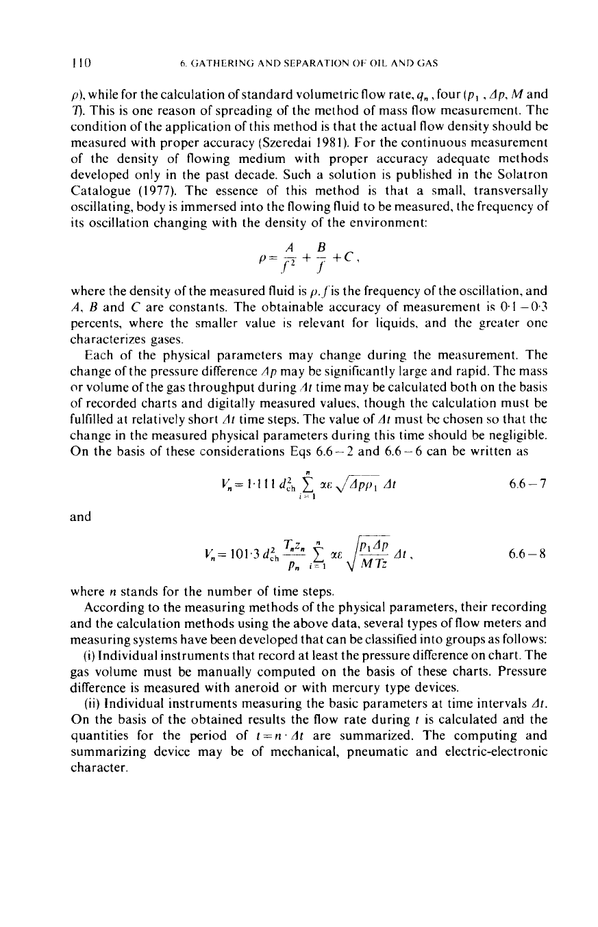
The critical flow prover is used, first of all, for the calibration of other, industrial
gas flow meters and for the testing
of
flow rates of new gas wells.
Figure
6.6
-6
shows
3
2
6
5
Section
A-A
Fig
66-6
Rawlins
and Schellhardt's critical
flow
prover
the critical flow prover designed by Rawlins-Schellhardt and used for this latter
purpose, in dismantled pieces (Szilas 1967). The measuring body
1
is mounted on the
pipe end open
to
the atmosphere. To this the orifice plate
2
is fixed by cover
3.
The
thermometer is placed in case
4
while the pressure gage is mounted
in
bore
5.
Hole
marked
6
is closed by a valve.
6.6.5.
Positive-displacement meters
In positive displacement meters, the liquid
or
gas enters a metering space of
known capacity, confined by pistons
or
plungers of various design and performing
motions
of
various types, and is then expelled therefrom. These meters may be
6.6
FLUID
VOLUME
MEASIJRFMENT
113
considered as hydraulic motors of high volumetric efficiency that adsorb energy
from the passing fluid as is required to keep in motion the moving parts of the
instrument. The effective volume of fluid is proportional to the number of strokes
if
the piston is reciprocating,
or
of revolutions
if
it
is of the rotating type. The effective
volume is, then, transformed in standard volume
or
mass. The parameters required
to this procedure (pressure, temperature and density, respectively) are measured
separately, similarly to the orifice metering, and the
PD
meters give automatically
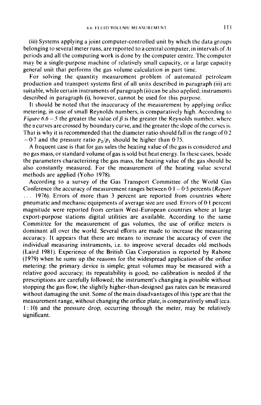
Fig.
6.6
-
7.
Principle
of
oval-gear positive-displacement meter, after Reppisch
(
19SX)
the corrected data. About
700
types of positive displacement meters are known.
In
the case of production and transport of oil and gas they are used first of all for oil
quantity measurement, and the oval-gear meter is the most popular, the principle of
which is shown
in
Fig.
6.6
-
7
(Reppisch
1958).
Every revolution of the pair of oval
wheels provided
with
spur gears lets pass theoretically constant amount of liquid.
Between the engaging gear-teeth
of
the two wheels, on the one hand, and the
gearbox and the wheel sweeping by it, on the other hand, there are gaps of a few
hundredths of millimeter width. Some of the liquid will pass unmetered through
these gaps.
At
higher flow rates, pressure difference due to friction and flow
resistance across the meter will increase, and
so
will leakage through the gaps, as an
almost linear function
of
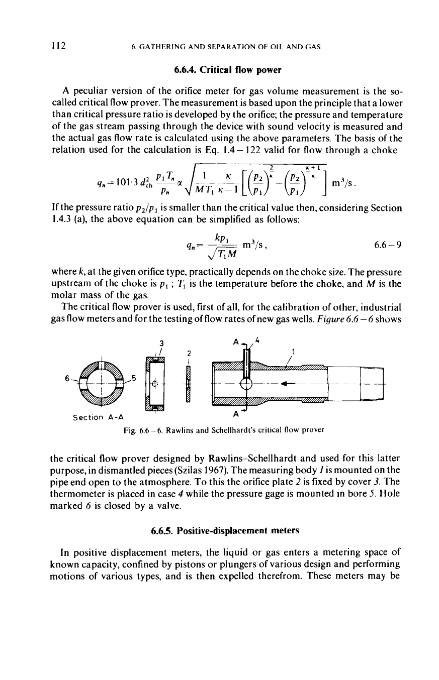
the pressure difference. Accurate metering requires
knowledge of the relative leakage
loss.
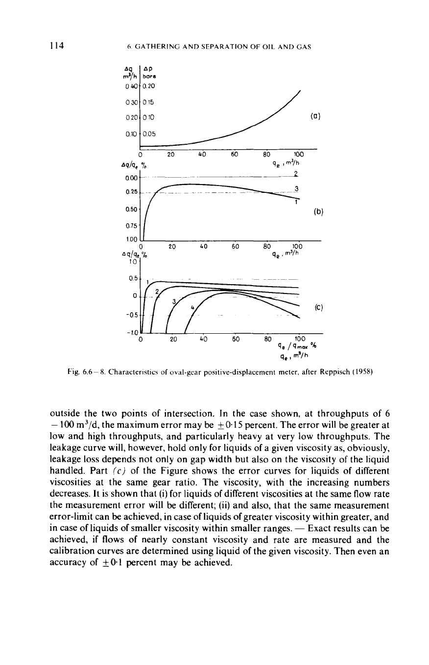
The upper part
(a)
of
Fig.
6.6-8
shows
pressure difference Ap across an oval-gear meter, and leakage dq, assumed to be
proportional to Ap,
v.
the effective flow rate qe through the instrument. Part
(b)
of
the Figure shows Aq/q,
v.
q,curve
(1)
(the percentage error ofmetering). In the ideal
case of no leakage, the instrument will indicate the actual throughput (line
2).
In
effect, however, actual throughput invariably exceeds by the leakage
loss
the volume
indicated by the meter,
if
no measures to the contrary are taken.
By
suitable
adjusting the variable gear ratio between oval gears and counter, however,
displacing line
2
into the position
of
line
3,
so
as to make the counter consistently
indicate more oil by
0.25
percent than
it
would in the ideal case; the error is made
zero where line
3
and curve
1
intersect, positive between the two points of
intersection (that is, the indicated throughput will exceed the actual), and negative
X
1
I4
6
GATHERING AND SEPARATION
OF OIL
AND GAS
030
015
020
L----/
010
(0)
010
005
0
20
40
60
80
100
Ad9,
000
0
25
0
50
0
75
100
1
n
an
t.n
.cn
an
Inn
."
0
20
40
60 80
100
Fig.
6.6-
8.
Characteristics
of
oval-gear positive-displacement meter. after Reppisch
(
1958)
outside the two points of intersection. In the case shown, at throughputs of
6
-
100
m3/d, the maximum error may be
iO.15
percent. The error will be greater at
low and high throughputs, and particularly heavy at very low throughputs. The
leakage curve will, however, hold only for liquids of a given viscosity as, obviously,
leakage
loss
depends not only on gap width but also on the viscosity of the liquid
handled. Part
(c)
of
the Figure shows the error curves for liquids of different
viscosities at the same gear ratio. The viscosity, with the increasing numbers
decreases. It is shown that
(i)
for liquids of different viscosities at the same flow rate
the measurement error will be different;
(ii)
and also, that the same measurement
error-limit can
be
achieved, in case of liquids of greater viscosity within greater, and
in case
of
liquids of smaller viscosity within smaller ranges.
-
Exact results can be
achieved,
if
flows of nearly constant viscosity and rate are measured and the
calibration curves are determined using liquid of the given viscosity. Then even an
accuracy
of
kO.1
percent may be achieved.
60
1
I
[Ill)
VOI
llMl
MI
ASliKI
MI
Nl
I
IS
There are instruments that continuously sense the flowing tcmpcrature and
correct the volume to standard temperature. The
Bopp
Reuther-typc instrumcnt
(FRG), a positive displacement meter compensating for temperature
is
a device of
this kind.
The accuracy of the net oil measurement may be significantly decreascd,
if
water
or gas bubbles, respectively, can be found
in
the measured oil. That is
why
thc watcr
content should be precisely measured, and getting of gas bubbles into thc
instruments should be prevented (see also Section
6.7.3
-
(b)).
1
10
a
Fig
66-9
Shell Pipe Line
Co'\
bdll-type
meter plover
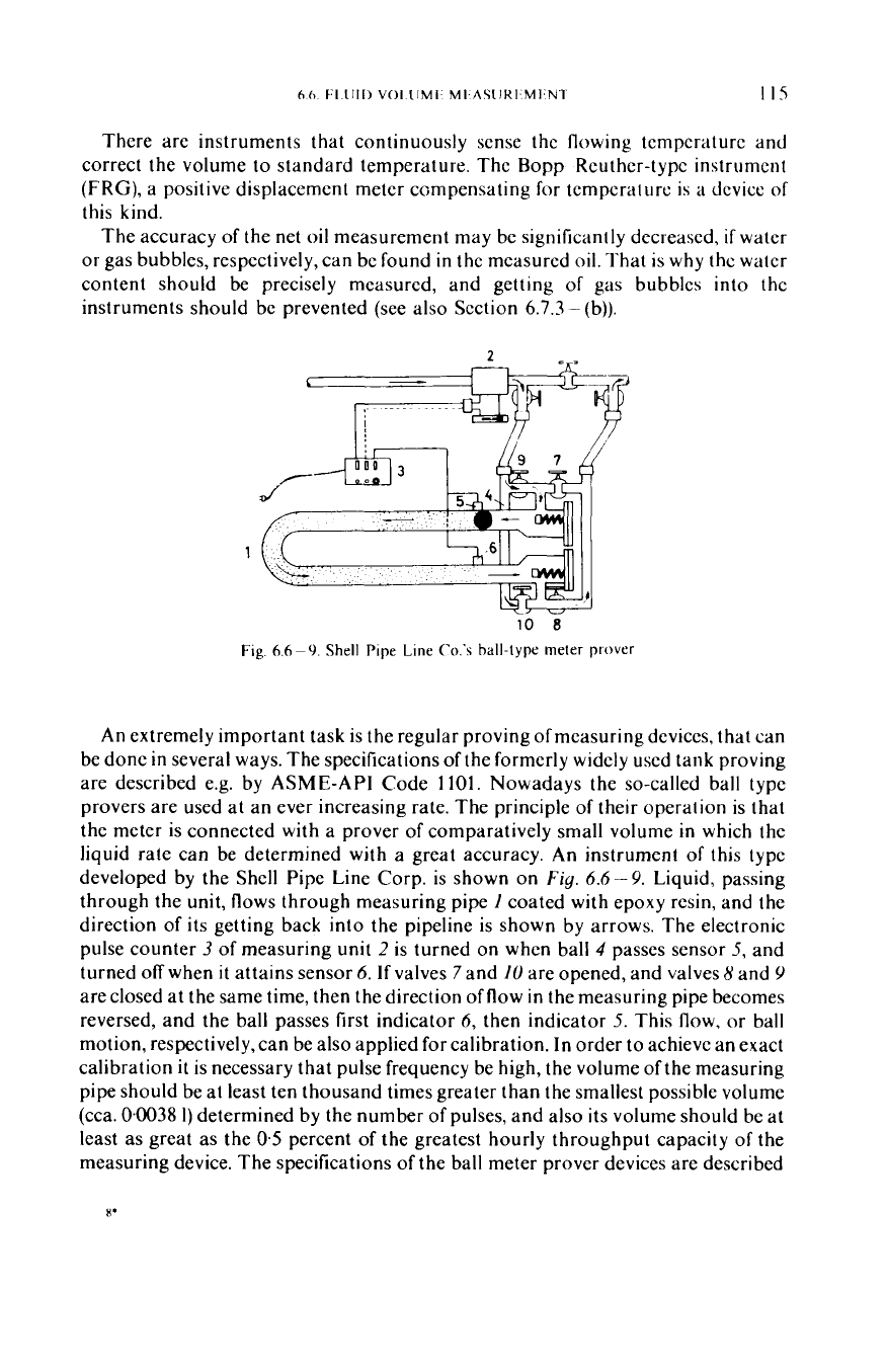
An
extremely important task is the regular proving
of
measuring devices, that can
be done
in
several ways. The specifications of the formerly widely used tank proving
are described e.g. by ASME-API Code
1101.
Nowadays the so-called ball type
provers are used at an ever increasing rate. The principle of their operation is that
the meter is connected with a prover of comparatively small volume
in
which the
liquid rate can be determined with a great accuracy.
An
instrument
of
this type
developed by the Shell Pipe Line Corp. is shown on
Fig.
6.6
-
9.
Liquid, passing
through the unit, flows through measuring pipe
1
coated with epoxy resin, and the
direction of its getting back into the pipeline is shown by arrows. The electronic
pulse counter
3
of measuring
unit
2
is turned on when ball
4
passes sensor
5,
and
turned
off
when
it
attains sensor
6.
If
valves
7
and
10
are opened, and valves 8 and
Y
are closed at the same time, then the direction offlow in the measuring pipe becomes
reversed, and the ball passes first indicator
6,
then indicator
5.
This flow, or ball
motion, respectively,can be also applied for calibration.
In
order to achieve an exact
calibration
it
is necessary that pulse frequency be high, the volume of the measuring
pipe should be at least ten thousand times greater than the smallest possible volume
(cca.
0.0038
1)
determined by the number of pulses, and also its volume should be at
least as great as the
0.5
percent
of
the greatest hourly throughput capacity
of
the
measuring device. The specifications
of
the ball meter prover devices are described
1
I6
h
(;ATHERING
AND
SEPARATION
OF
011.
AND
<;AS
in
API
Code 2531 (Komich 1973). Since these instruments are rather expcnsive.
in
order
to
decrease their costs, versions including no valves were
also
developed
(O'Donnell 1973).
Beside its several advantages the positive displacement meter is liablc to several
errors as well, i.e.
it
is very sensitive as for the solid contaminations are concerned.
It
can cause the rapid wear of the instrument that may result in a rapid decrcasc
in
the
accuracy of the measurement, in the stopping of the wheels. and even
in
their
fracture.
In
these latter cases the liquid transport through the measuring instrument
also ceases.
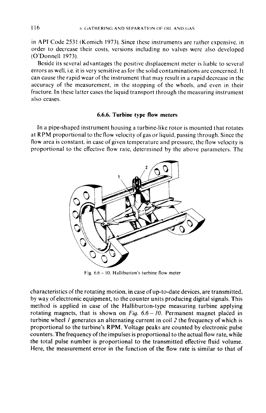
6.6.6.
Turbine type
flow
meters
In a pipe-shaped instrument housing a turbine-like rotor is mounted that rotates
at
RPM
proportional to the flow velocity ofgas or liquid. passing through. Since the
flow area is constant,
in
case of given temperature and pressure, the flow velocity is
proportional to the effective flow rate, determined by the
-
above parameters. The
Fig.
6.6-
10.
Halliburton's turbine
flow
meter
characteristics
of
the rotating motion, in case of up-to-date devices, are transmitted,
by way
of
electronic equipment, to the counter units producing digital signals. This
method is applied
in
case of the Halliburton-type measuring turbine applying
rotating magnets, that is shown on
Fig.
6.6-
10.
Permanent magnet plated
in
turbine wheel
I
generates an alternating current in coil
2
the frequency
of
which is
proportional to the turbine's
RPM.
Voltage peaks are counted by electronic pulse
counters. The frequency of the impulses is proportional to the actual flow rate, while
the total pulse number is proportional to the transmitted effective fluid volume.
Here, the measurement error in the function of the flow rate is similar to that
of
66
I-LUII)
VOLIJME
MLASIIR1,Ml
Nl
1
I7
t
7)
961
I
I,
r7-T
r
T
1
T-T-77
I1
I
0
10
20
30
40
50
60
70
80
90
100
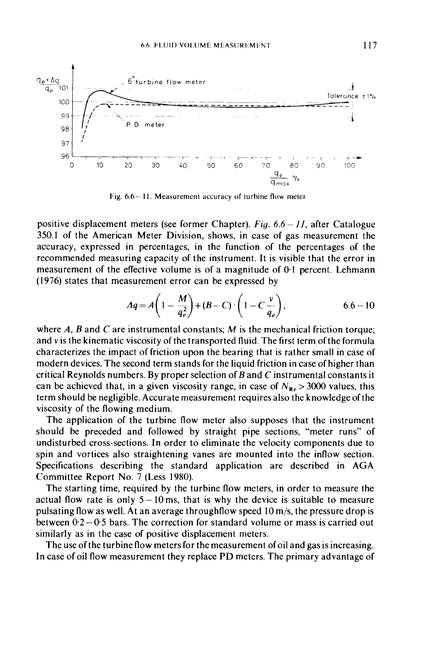
Fig.
6.6-
11.
Measurement accuracy
of
turbine
flow
meter
positive displacement meters (see former Chapter).
Fig.
6.6
-
I I,
after Catalogue
350.1
of the American Meter Division, shows,
in
case of gas measurement the
accuracy, expressed
in
percentages, in the function of the percentages of the
recommended measuring capacity
of
the instrument.
It
is visible that the error
in
measurement of the effective volume is of
a
magnitude of
0.1
percent. Lehmann
(1976)
states that measurement error can be expressed by
6.6-
10
where
A,
B
and
C
are instrumental constants;
M
is the mechanical friction torque;
and
v
is the kinematic viscosity of the transported fluid. The first term of the formula
characterizes the impact of friction upon the bearing that is rather small
in
case of
modern devices. The second term stands for the liquid friction
in
case of higher than
critical Reynolds numbers. By proper selection
of
B
and
C
instrumental constants
it
can be achieved that, in a given viscosity range,
in
case of
N,,
>
3000
values, this
term should be negligible. Accurate measurement requires also the knowledge of the
viscosity of the flowing medium.
The application of the turbine flow meter also supposes that the instrument
should be preceded and followed by straight pipe sections, “meter runs” of
undisturbed cross-sections. In order to eliminate the velocity components due to
spin and vortices also straightening vanes are mounted into the inflow section.
Specifications describing the standard application are described
in
AGA
Committee Report
No.
7
(Less
1980).
The starting time, required by the turbine flow meters, in order to measure the
actual flow rate is only
5-
lOms, that is why the device is suitable to measure
pulsating flow as well.
At
an average throughflow speed
10
m/s, the pressure drop is
between
0.2-0.5
bars. The correction for standard volume or mass is carried out
similarly as in the case
of
positive displacement meters.
The use of the turbine flow meters for the measurement of oil and gas is increasing.
In case of oil flow measurement they replace PD meters. The primary advantage of
118
6.
GATHERING AND SEPARATION
OF
OIL
AND
GAS
turbine flow meter is, that
it
is less sensitive to the solid contaminations, its wear is
slower, and even
if
the rotor stops,
it
does not hinder the flow. Morse (1976)
summarizes the results of experiments, carried out at seven oil fields for years, by
which the aim was to determine which ofthe two measuring instruments can be used
more efficiently for oils containing emulsion
or
solid contamination. The test result
showed
that, during the operating period, the repeatability of the positive
displacement meters was
f0.81
percent, while the same value for turbine meters is
kO.41.
The life of turbine flow meters proved to be eleven times longer, and the
change of the meter factor during the testing period was half as much as that of the
positive displacement meters.
Turbine flow meters are increasingly applied also for the measurement of large
gas flow rates.
An
advantage as compared
to
orifice metering is that
it
rapidly adapts
itself to the fluctuating flow rates and the measurement accuracy,
in
case of modern
devices, may even reach
0.25
percent,
if
calibration is carried out at approximately
the same pressure as that of the measurement. Several methods are applied for
calibration. Wager (1977) is for the application of the critical flow prover equipped
with a Venturi tube, since by this deviceeven a measurement accuracy of0.2 percent
can be obtained. Most frequently, however, the series-connected master meters are
used.
For
the calibration of oil measuring turbine flow meters, similarly to the
positive displacement meters, ball provers are widely used. The largest device of this
kind was developed
in Japan,
in
1974. Its capacity is 8000m3/h while its
repeatability is
kO.02
percent. The meter proving process may be significantly
simplified by applying the so-called European method, the essence of which is that
calibration needs not be carried out for oils of each possible viscosity since one
calibration is enough. Here, in the function of
q/v,
proportional to the Reynolds
number, an universal error function is determined. The tests were carried out by
using Sereg turbine meters (Sereg-Schlumberger 1978).
6.6.7.
Other measurements
Measuring oil flow by any instruments
it
can occur that the stream contains water
too, and the net oil flow rate can be determined only
if
the water content is also
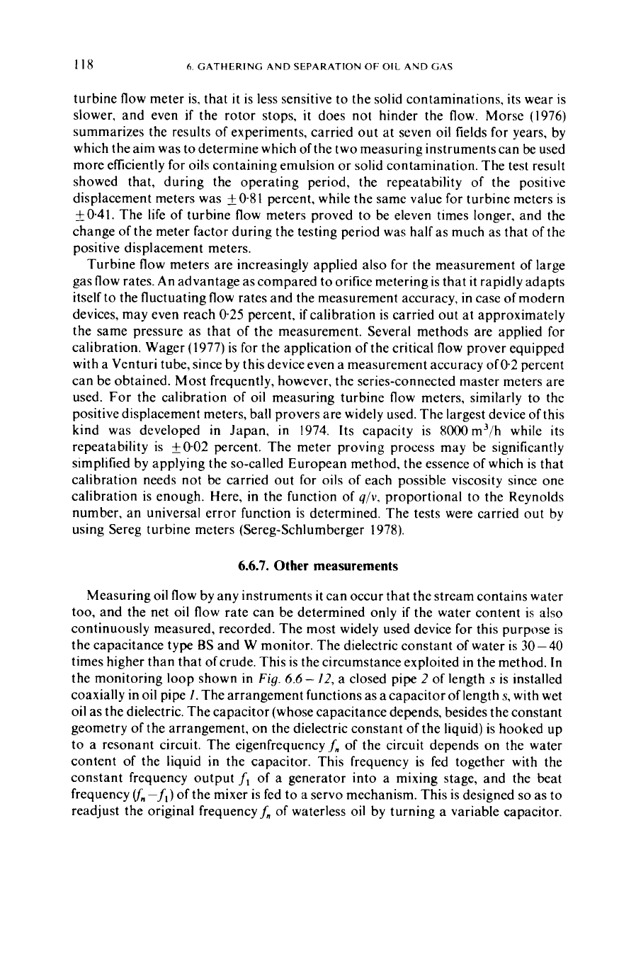
continuously measured, recorded. The most widely used device for this purpose is
the capacitance type
BS
and W monitor. The dielectric constant of water is 30-40
times higher than that ofcrude. This is the circumstance exploited in the method.
In
the monitoring loop shown in
Fig.
6.6
-
12, a closed pipe
2
of
length
s
is installed
coaxially in oil pipe
I.
The arrangement functions as a capacitor of length
s,
with
wet
oil as the dielectric. The capacitor (whose capacitance depends, besides the constant
geometry of the arrangement, on the dielectric constant of the liquid) is hooked up
to a resonant circuit. The eigenfrequencyf, of the circuit depends on the water
content of the liquid in the capacitor. This frequency is fed together with the
constant frequency output
fi
of a generator into a mixing stage, and the beat
frequency
rm-f,)
of the mixer is fed to a servo mechanism. This is designed
so
as to
readjust the original frequencyf, of waterless oil by turning a variable capacitor.
6.6
FLUID
VOLlJME
MEASUREMENT
I19
This turning, suitably amplified, serves as a measure of water content against an
experimentally calibrated dial. Experience has shown this instrument to operate to
about
50
percent water only.
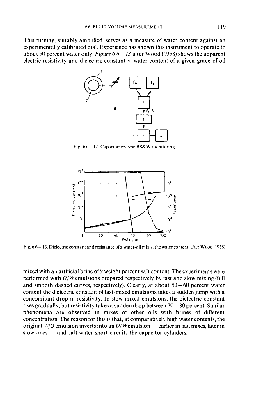
Figure
6.6
-
13
after Wood
(1958)
shows the apparent
electric resistivity and dielectric constant
v.
water content of a given grade of oil
Fig
6
6
-
I2
Capacitance-type
RS&W
monitoring
10
'
c
0
lo*
'0
lo3
p
107
+
9
L
c
u
n
10
lo6
105
:
C
0
c
loc
:
u
n
10'
1
20
40
60
80
100"
Fig.
6.6-
13.
Dielectric constant and resistance
of
a water-oil mix
v.
the water content. after
Wood
(1958)
Water,
%
mixed with an artificial brine
of
9
weight percent salt content. The experiments were
performed with
O/
Wemulsions prepared respectively by fast and slow mixing (full
and smooth dashed curves, respectively). Clearly, at about
50-
60
percent water
content the dielectric constant
of
fast-mixed emulsions takes a sudden jump
with
a
concomitant drop in resistivity. In slow-mixed emulsions, the dielectric constant
rises gradually, but resistivity takes a sudden drop between
70-
80
percent. Similar
phenomena are observed in mixes of other oils with brines of different
concentration. The reason for this is that, at comparatively high water contents, the
original
W/O
emulsion inverts into an O/Wemulsion -earlier in fast mixes, later in
slow ones
-
and salt water short circuits the capacitor cylinders.