Satas D., Tracton A.A. (ed.). Coatings Technology Handbook
Подождите немного. Документ загружается.

52
250
200
Separation
in
Angstrom
Units
100
50
20
1
DAHLQUIST
10
100
Force
Constant
l000
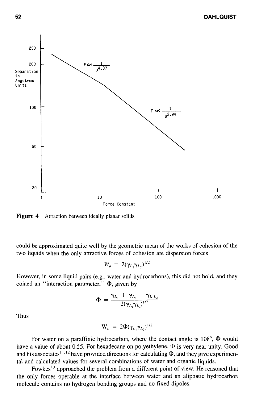
Figure
4
Attraction between ideally planar
solids.
could be approximated quite well by the geometric mean of the works of cohesion
of
the
two liquids when the only attractive forces of cohesion are dispersion forces:
W,,
=
2(YIJl,J
I
l2
However, in some liquid pairs (e.g., water and hydrocarbons), this did not hold, and they
coined an “interaction parameter,”
Q,
given by
For water on
a
paraffinic hydrocarbon, where the contact angle is log”,
Q,
would
have a value of about
0.55.
For hexadecane on polyethylene,
Q,
is very near unity. Good
and his associates”.” have provided directions for calculating
Q,
and they give experimen-
tal and calculated values for several combinations
of
water and organic liquids.
FowkesI3 approached the problem from
a
different point of view. He reasoned that
the only forces operable at the interface between water and an aliphatic hydrocarbon
molecule contains no hydrogen bonding groups and no fixed dipoles.
THE THEORY
OF
ADHESION
53
Fowkes also assumed that the work of adhesion would be given by twice the geomet-
ric mean
of
the surface energies of the two liquids on either side of the interface, but now
taking into consideration only the dispersion force components of the surface energies.
For the work of adhesion between water
(LI)
and n-octane
(L2).
we have
W,,
=
2(Y;,Y:j,)”’
=
YL,
+
YL,
-
YL,L,
where the superscript
D
stands for the dispersion energy component of the total surface
energy. Accepted values for the surface energies and interfacial energies are:
yr.,
=
72.8 ergdcm’;
yL.
=
$!,
=
21.8 ergdcm’; y12,r.2
=
50.8 ergs/cm’
If these values are substituted into the equation above to solve for
YE,”,
we get 22.0 ergs/
cm’. Fowkes evaluated several water-aliphatic hydrocarbon systems and found that they
all yielded essentially the same value for the dispersion energy component of the surface
energy of water, 21.8
*
0.7 ergdcm’.
Turning now to the work
of
adhesion and the interfacial energy between mercury
and aliphatic hydrocarbon, Fowkes calculated the dispersion energy component of the
surface energy
of
mercury.
Using n-octane as the hydrocarbon liquid having
a
surface energy of 21.8 ergdcm’
(all
of
it attributed to dispersion forces), the surface energy of mercury, 484 ergskm’, and
the interfacial energy, 375 ergskm’, we have
W,,
=
2(Y~gY~-oct)”’
=
YH,s
+
Y,IPOCt
-
Y(H,S.,l
-<)cl)
W,,
=
2($$
X
21.8)”’
=
484
+
21
.8
-
375
=
196.2
The average for
a
series of mercury-aliphatic hydrocarbon systems yielded 200
2
7
ergs/cm’ for the dispersion energy component of the surface energy of mercury.
Since the remaining forces that contribute
to
the surface energy of mercury are
metallic forces, the only interacting forces at the water-mercury interface are the dispersion
forces, and the work of adhesion is given by:
W,,
=
2(200
X
21.8)”’
=
484
+
72.8
-
Y(H,,
H,())
from which
Y,~,,
f.l,O)
=
424.7 ergs/cm’
This compares very favorably with the measured value of 426 ergskm’.
The work of adhesion due to dispersion forces is numerically small in work or
energy units. For example, the work of adhesion of methylene iodide on polyethylene is
82 ergskm’
(0
=
52”). This small value is not, however, indicative
of
a
small force of
attraction across the interface. Keep in mind that the work is the product of force and
displacement, and that the attractive force, at separation distances less than
50
A
(5
X
10”
cm) increases
as
the inverse of displacement raised
to
the third power (Fig.
4).
The molecules at the interface are at an equilibrium distance of separation where
attractive forces and repulsive forces balance. The variation
in
the repulsive forces with
distance
of
separation has a dependence several orders of magnitude higher than the attrac-
tive forces (of the order of
10”
for atom pairs and
10’
for repulsion forces across a
hypothetical plane). We can calculate the maximum force
of
attraction by equating the
work of adhesion
to
the work of separation.
54
DAHLQUIST
Let
F,,
indicate the attractive force,
F,
the repulsive force, x the distance separation,
and d the equilibrium distance. We cannot measure d directly, but we can estimate it from
calculations
of
the distance between molecular centers in
a
liquid of known specific gravity
and molecular weight. In the case
of
methylene iodide (sp
g
3.325, mol wt
267.9)
we
calculate the separation to be about
5
X
lov8
cm between the centers of adjacent mole-
cules.
If we take
5
X
lo-’ cm
as
a
reasonable distance of separation across the interface
between methylene iodide and polyethylene, and we accept the force versus distance
relationships for attraction
(a)
and repulsion
(r)
we can write:
where the subscript
e
stands for “equilibrium.” At equilibrium we have the condition
that
(F(,)(,
=
(F,.)<..
We can then express the work of adhesion as
The solution is
For methylene iodide on polyethylene,
W,,
is 82 ergdcm’. Taking
d
as
5
X
IO-’
cm,
F,,
=
F
=
F,.
=
4.92
x
lo9
dyneskm’.
The maximum attractive force is encountered where the difference between the
attractive forces and the repulsive forces maximizes
as
separation proceeds. This occurs
where (d/x)3
-
(d/~)~ maximizes, at about x
=
1.22d.
At this displacement
F
=
0.347F,.,
or, in the case of methylene iodide and polyethyl-
ene, at
1.71
X
lo9
dyneskm’ (about 25,000 psi). This would be the maximum attractive
force experienced when separation of the materials is attempted; it far exceeds the average
stresses that are typically observed when adhesive bonds are broken.
Others have calculated theoretical forces of adhesion by other approaches. All yield
results that predict breaking strengths
far
exceeding the measured breaking strengths.
3.0
REAL AND IDEAL ADHESIVE BOND STRENGTHS
How, then, does one account for the fact that theoretical or ideal bond strengths do not
seem to be attainable? The measured cohesive strengths of solids
also
fall far short
of
theoretical values. Only whisker crystals of silicon, graphite, iron, and the like have mea-
sured tensile strengths approaching their theoretical tensile strengths.
J.
J.
Bikerman contended that all adhesive bonds are flawed and contain weak bound-
ary layers, hence always fall short
of
their theoretical strengths. Undoubtedly this is often
the case; but flaws, at least gross flaws, can be minimized, and fracture in weak boundary
layers, which can be detected, is not always observed.
All destructive tests, whether done in tension, shear, or peel, involve stress concentra-
tions. Unless the stress is uniformly distributed over
a
very small area, as in the tensile
THE THEORY
OF
ADHESION
55
25
20
X
W
E
V
\
a,
S
V
z1
v)
a,
v)
.W
L
v)
a,
L
3
15
10
0
0.1
0.2
0.3
0.4
Thickness
of
adhesive
layer,
cm.
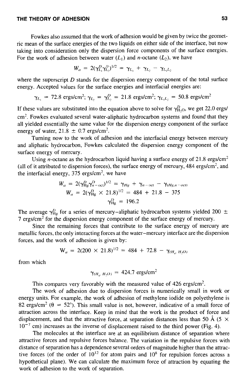
Figure
5
Adhesive layer thickness
and
strength
of
butt joints.
strength tests on the “whiskers,” there will be localized stresses that far exceed the average
stress. It is well known that the measured average breaking strengths of adhesive bonds
broken in tension decrease
as
the adhesive thickness increases (Fig.
5),
and it can be shown
that tensile stresses at the periphery
of
the bond are higher than interior stresses. If
a
flaw
leads to highly localized stress, cleavage may be initiated and proceed catastrophically.
Bonds pulled in shear not only experience shearing stress concentrations but also
tearing stresses.’4.’s Peeling is a deliberate application of stress concentration.
Deformation and flow also contribute to stress concentrations and failure. It would
be advantageous to match the mechanical properties of the adhesive to the mechanical
properties of the adherend, but this is rarely feasible. Instead, the adhesive designer resorts
to the expedient of toughening the adhesive and incorporating materials that arrest crack
propagation, thereby maximizing the work necessary to destroy the bond.
In many instances the adhesive-adherend interface is more accurately described as
an “interphase.” A case in point is the bonding
of
aluminum to aluminum with structural
adhesive. The surface
of
aluminum is really aluminum oxide, which, depending on the
manner in which it was formed, will vary in strength and porosity. The adhesive penetrates
and locks into the oxide film, and the bond strength can be greatly enhanced by use
of
a
surface treatment that produces a strong, well-bonded oxide layer.
Adhesive-adherend bond strengths are often enhanced by priming. A classic exam-
ple is the bonding of vulcanized rubber to steel, in which the steel is first electroplated
with a thin coat of copper and the rubber compound is cured on the copper surface under
heat and pressure. It is believed that the sulfur in the vulcanizate bridges to the copper
by chemical bonding to give
a
strong bond, and the copper in turn is strongly bonded to
the steel.
56
DAHLQUIST
Priming is often used on bonding adhesives to plastic films. For example, the first
transparent pressure-sensitive tape, which comprised a cellophane film and a natural rubber
rosin adhesive, would undergo separation of the adhesive from the film under humid
conditions. The problem was solved by first applying to the cellophane,
a
thin prime coat,
a
blend of natural rubber and casein, then coating the adhesive over the primer.
Surfaces notoriously difficult to bond to, such
as
polyethylene, polypropylene, and
Teflon, are modified by treatments that make the surfaces more polar and possible chemi-
cally active, for example, by corona, plasma, or chemical treatments. These treatments
may also remove weak boundary layers.
Though strong, durable adhesive bonds are usually the goal of adhesive technology,
there is also a need for bonds that are deliberately made weak. This need arises in the
pressure-sensitive tape industry, where it is desirable to have tape that unwinds easily
from the roll, and especially where pressure-sensitive adhesives are to be transferred from
a
carrier film to another surface. The surfaces that provide easy release typically have low
critical surface energies, almost totally dominated by the “dispersion energy” component.
Also,
for release coatings to function well, there must be no mutual solubility between
them and the adhesives. Silicone release coatings, which consist mainly
of
polydimethyl
siloxane, provide the easiest release. They have low critical surface energies, though not
as low
as
certain fluorocarbon polymers. They
also
have
a
high degree of incompatibility
with the pressure-sensitive adhesives that release well from them, but these criteria alone
do not explain the low level of adhesion. In addition, they differ from other release coatings
by being soft and elastic rather than hard. This feature may serve to enhance the stress
concentration when the adhesive is separated from the release liner.
In conclusion, adhesive bond strengths measured by destructive tests will never
approach theoretical values, but the intrinsic attractive forces can be manipulated by the
choice of materials and surface treatments
to
produce a wide range of practical bond
strengths.
REFERENCES
1. T. Young,
Phil.
Trcrns.
R.
Soc.
London,
95,
65 (1805).
2.
W.
D.
Harkins and
H.
K.
Livingston,
J.
Chern.
Phys.,
10,
342 (1942).
3.
A.
DuprC,
ThPorie MPcnnique
de
Icr
Chleur,
Paris,
1869.
p.
393.
4.
W.
A.
Zisman,
lnd.
Eng.
Chetn.,
55.
18 (1963).
5.
E.
G. Shafrin, in
Polymer
Handbook,
J.
Brandrup and E.
M.
Irnrnergut, Eds. New York: Wiley-
6.
F. London,
Trcrns. Ftrrcrelay
Soc..
33.
8
(1936).
7.
R.
S.
Drago, L. B. Parr, and C.
S.
Chamberlain,
J.
Anr.
Chetn.
Soc.,
99,
3203 (1977).
8.
F.
M.
Fowkes,
J.
Ar1ke.s.
Sci.
Techno/..
1.
7 (1987).
9.
H.
B.
C.
Casirnir
and
D.
Polder,
Phvs.
Ret,..
73,
360 (1948).
10.
E.
M.
Lifshitz,
C.
R.
Acnd.
Sci.
USSR,
97,
643
(
1954).
11.
D.
Tabor and R.
N.
S.
Winterton,
Nature,
219,
1120 (1968).
12.
L.
A.
Girifalco and R.
J.
Good,
J.
Phys.
Chetn.,
61,
904 (1957).
13.
F.
M.
Fowkes,
J.
Phys.
Chem.,
66,
382 (1962).
14.
0.
Volkersen,
Luftfirhrforschung,
15,
41 (1938).
15.
M.
Goland and
E.
Reissner,
J.
Appl.
Mech.,
Trcrns.
ASME.
66,
17 (1944).
Interscience,
1966,
pp.
1 1
1-1
13.

Adhesion Testing
Ulrich
Zorll
Forschung.sinstitut fir Pigmente
und
Lrrcke,
Stuttprt, Germanv
1
.O
FUNDAMENTALS OF ADHESION
Without sufficient adhesion,
a
coating
of
otherwise excellent properties in terms
of
resis-
tance to weather, chemicals, scratches, or impact would be rather worthless. It is therefore
necessary to provide for good adhesion features when paint materials
are
formulated.
There must also be adequate means for controlling the level of adhesion strength after the
coating has been spread and cured
on
the substrate. Moreover, methods should be available
that allow for the detection of any failure in the case of the dissolution of the bond between
coating and substrate, under any circumstances whatsoever.
1
.l
Components at the Interface
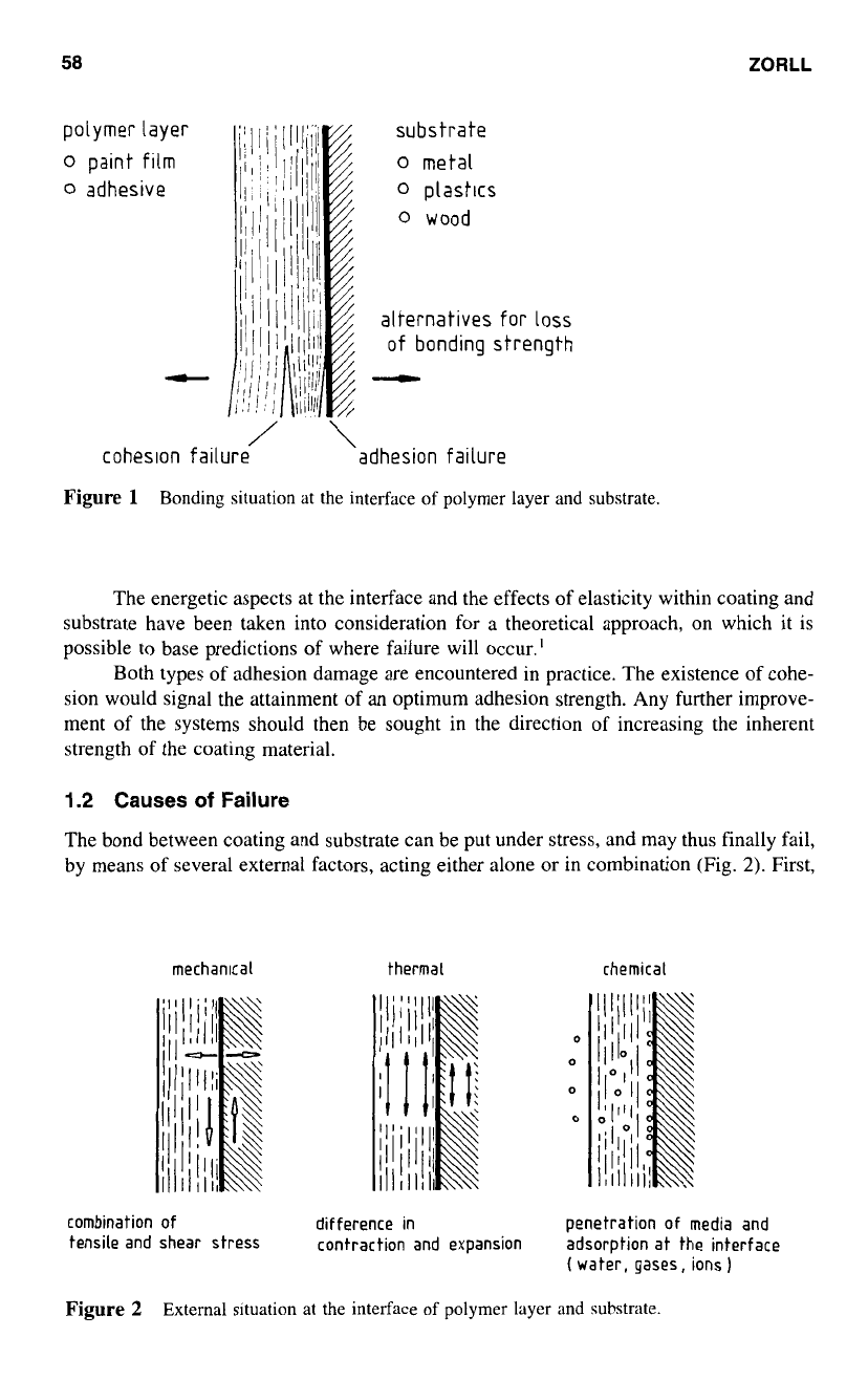
In chemical terms, there is
a
considerable similarity between paints on one side and adhe-
sives or glues on the other (Fig.
1).
Both materials appear in the
form
of organic coatings;
thus it is appropriate in this chapter to concentrate on the behavior of paint materials.
Adhesion is the property requested in either case, though perhaps with different emphasis
on its intensity, according to the intended use.
Such a coating is, in essence,
a
polymer consisting of more or less cross-linked
macromolecules, and
a
certain amount of pigments and fillers. Metals, woods, plastics,
paper, leather, concrete, or masonry, to name only the most important materials can form
the substrate for the coating.
It is, however, important to keep in mind that these substrate materials may inhibit
a
rigidity higher than that of the coating. Under such conditions, fracture will occur within
the coating, if the system experiences external force of sufficient intensity. Cohesive failure
will be the consequence, however, if the adhesion at the interface surpasses the cohesion
of the paint layer. Otherwise, adhesive failure is obtained, indicating
a
definite separation
between coating and substrate.
57
58
ZORLL
The energetic aspects at the interface and the effects of elasticity within coating and
substrate have been taken into consideration for
a
theoretical approach, on which it is
possible to base predictions
of
where failure will occur.'
Both types of adhesion damage are encountered in practice. The existence of cohe-
sion would signal the attainment of an optimum adhesion strength. Any further improve-
ment of the systems should then be sought in the direction of increasing the inherent
strength
of
the coating material.
1.2
Causes
of
Failure
The bond between coating and substrate can be put under stress, and may thus finally fail,
by means of several external factors, acting either alone
or
in combination (Fig.
2).
First,
mechanlcal thermal chemical
combination of
difference
in
penetration
of
media and
tensile and shear stress
contraction and expansion
adsorption at the interface
(
water, gases, ions
1
Figure 2
External situation at the interface
of
polymer layer and substrate.
ADHESION TESTING
59
there may be regular mechanical stress, affecting not only the bulk of the materials but
also the bond strength at the interface. It is useful here
to
distinguish between the two
most common types of stress: tensile stress, effective perpendicularly to the interface, and
shear stress, appearing along the plane
of
contact.
Moreover, since coatings may undergo changes in temperature, sometimes even
rather rapidly, any difference in the coefficient
of
expansion can cause at the interface
stress conditions of such high intensity that the paint film becomes detached from the
substrate. This event may be especially disadvantageous because the temperature effects
tend to be less obvious than the mechanical and chemical factors.
There may be, of course, an effect of
a
chemical, which penetrates through the
coating and becomes absorbed at the interface, causing
loss
of adhesion here.
It is always useful to take these effects into consideration when adhesion must
be measured, because the method of testing the coating should reproduce the end-use
conditions.
1.3
Measures
of
Adhesion
There are various possibilities for characterizing the results obtained in an adhesion test.
If it is necessary to evaluate the bonding strength at the interface, the quantity to be
measured
is
obviously the maximum mechanical stress that can be attained at the interface.
This is adhesion strength in the strict sense, expressed
as
force per unit area, and specified
as
either tensile or shear stress. Consequently, in several test methods, the result is obtained
in that form.
The energy that must be provided for breaking the bond at the interface can
also
be an informative quantity. It is expressed
as
work
of
adhesion and is formally equivalent to
the product of adhesion strength,
as
defined earlier, and the distance between the separated
surfaces of coating and substrate immediately after detachment. Thus, that quantity has
the dimensions
of
force per unit length, and this is exactly the value obtained with some
other test methods e.g., the peeling test.
2.0
STANDARDIZATION
OF
ADHESION TESTS
Since
a
specification for the degree of adhesion must be provided in nearly each paint
formulation, it is not surprising that methods for routine measurement of that key quantity
have been established in the field of quality testing. This is true for the cross-cut test. the
paint technicians’ first choice when adhesion must be estimated. However, the cross-cut
test is nowadays more and more complemented by the pull-off methods.
Both methods have been the subject of national standardization. However, the differ-
ences in the documents of various countries are of minor importance, and it was relatively
easy to formulate international standards, ensuring that these fundamental tests can be
carried out in a uniform manner.
2.1
Cross-Cut Test
Scope and procedure of practical and instructive method have been laid down by the
International Organization for Standardization
(ISO).’
To obtain an idea of the adhesion
of the coating,
a
lattice pattern is cut into it, penetrating through the film and into the
substrate. Various cutting tools can be used either manually or mechanically for this

60
ZORLL
appearance of
cross-cut area
percentage
of
flaking
0%
<
5
O/O
<
15
‘/o
35%
<
65
‘10
classification
0
1
2
3
4
Figure 3
Principle of classifying paint film adhesion in the cross-cut test.
purpose. A good choice is the multiple cutting tool,
a
set of six “knives,”
1
or
2
mm
apart, yielding
a
uniform pattern.
The test results are evaluated according
to
the scheme indicated in Figure
3.
The
classification is based on estimating the amount of paint flakes separated from the substrate.
If in doubt about the real percentage of detachment, one may brush off the loose parts,
or remove them by means
of
an adhesive tape.
It is not always necessary to base the judgment about the degree of adhesion on the
whole six-step classification. The
IS0
recommends standard considering the test for “go-
no go” statements. In such case, class
“0”
would indicate perfect adhesion, whereas class
“2.”
or even class
“
1
,”
should be interpreted as an objectionable result. All higher classes
would then signal, although with different distinctness, that something must be done to
improve the coating’s adhesion.
2.2
Tensile Methods
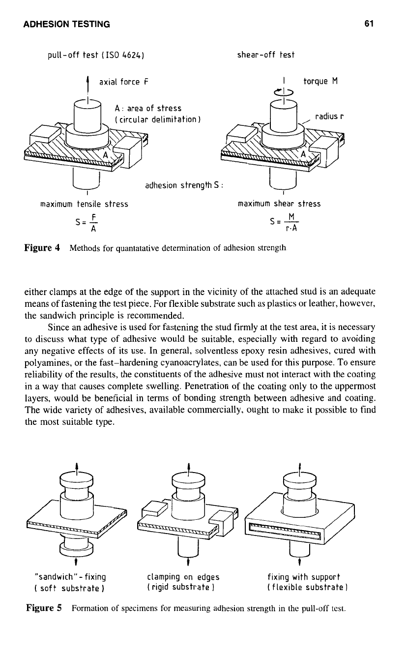
The typical stress patterns at the interface, caused by loads acting predominantly either
normal or parallel to the plane of contact, have been used as the basis for pertinent test
methods (Fig.
4).
The pull-off method is the most widely used procedure and has already
been standardized internationally.’
As
a
preparation for the test,
a
stud, normally made
of steel. is glued with the coating and is subjected
to
axial tension until detachment of
the paint film occurs. The result i.e., the adhesion strength is the maximum tensile stress
that is possible at the interface.
If, however, a torque is applied about the axis
of
the stud, the process of detachment
reveals the maximum shear stress that can be attained at the interface, thus also leading
to
a
characteristic measure of adhesion.
It has been shown‘ that the value
of
adhesion strength obtained from either method
are of the same order
of
magnitude. However, there is a tendency to obtain results with
the torque principle in the case of cohesive failure, but lower results for adhesive failure.
The accuracy, with which the tests can be carried out, and the existence
of
a
well-
defined mechanical principle for them, must not, however, lead
to
the idea that the values
obtained in this way can be considered to be material constants for the bonding components.
There is, instead, an additional influence
of
several parameters, such
as
temperature, speed
of
deformation, and even form and size of the stud.
Also of importance are the rigidity
of
the test piece and the possibility of securing
it for measurement.’ As shown in Figure
5,
for coatings on undeformable substrates, using
ADHESION TESTING
61
pull-off test
(IS0
46241
shear-off test
1
axial force
F
I
torque
M
CI,
A:
area of stress
(
circular delimitation
1
radius
r
adhesion strength
S
:
I
I
maximum tensile stress maximum shear stress
F
M
S=-
A
S=
-
r.A
Figure
4
Methods
for
quantatative determination
of
adhesion strength.
either clamps at the edge of the support in the vicinity of the attached stud is an adequate
means of fastening the test piece. For flexible substrate such as plastics or leather, however,
the sandwich principle is recommended.
Since an adhesive is used for fastening the stud firmly at the test area, it is necessary
to
discuss what type
of
adhesive would be suitable, especially with regard
to
avoiding
any negative effects
of
its use. In general, solventless epoxy resin adhesives, cured with
polyamines, or the fast-hardening cyanoacrylates, can be used for this purpose.
To
ensure
reliability
of
the results, the constituents of the adhesive must not interact with the coating
in a way that causes complete swelling. Penetration of the coating only to the uppermost
layers, would be beneficial in terms of bonding strength between adhesive and coating.
The wide variety of adhesives, available commercially, ought to make it possible to find
the most suitable type.
t
"sandwich"- fixing
clamping on edges fixing with support
(
soft substrate
1
(rigid substrate
) (
flexible substrate
1
Figure
5
Formation
of
specimens
for
measuring adhesion strength in the
pull-off
tcst.