Sandau R. Digital Airborne Camera: Introduction and Technology
Подождите немного. Документ загружается.

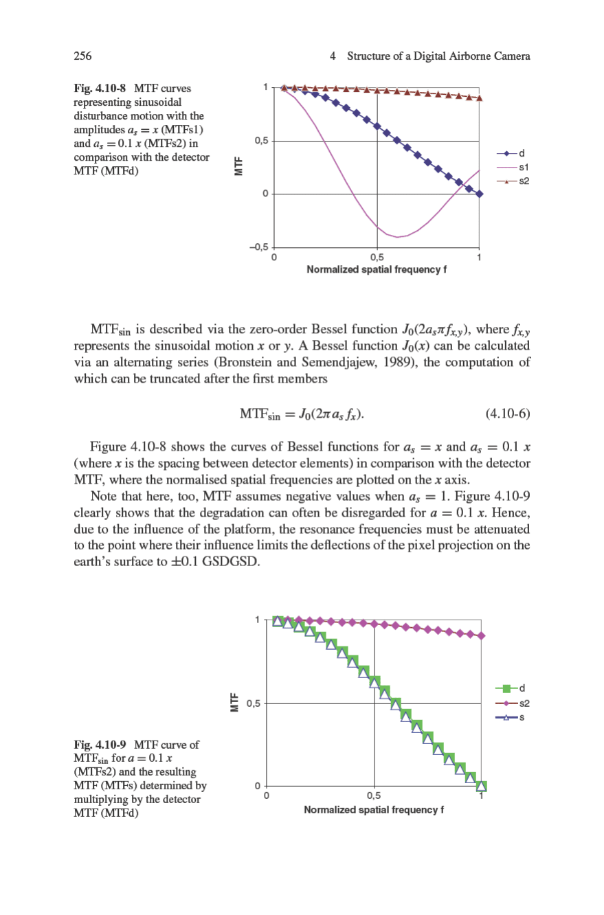
258 4 Structure of a Digital Airborne Camera
–6°
–3°
0°
3°
6°
Original strip
Rectified strip
Roll
Pitch
Yaw
Fig. 4.10-11 Uncontrolled camera mount
and yaw were relatively severe. Image distortion could be rectified with the aid of
data from a POS (position and orientation system). The high correlation between
the roll values and the attitude variations in the distortion-corrected image can be
clearly seen. Positional variations are significantly reduced by using a controlled
mount, so that only small lateral overlaps of the flight strip are required.
4.10.4 Controlled Camera Mount
Controlled mounts with automatic image stabilisation and automatic attitude control
meet two requirements. Image stabilisation has the same requirements and charac-
teristics for both analogue and digital airborne cameras. The input values to the
control loop are the angular velocities of the three axes, which are measured by
gyros, and the objective is to keep the residual angular velocities as low as possible.
It is expected that when a controlled mount is used, the residual angular velocity for
the remaining maximum image smear remains below 0.3
◦
/s.
Attitude control supports the control loop of the image stabilisation system. In
analogue film cameras, the mount must be controlled in such a way that deviations
4.10 Camera Mount 259
from the nadir caused by roll and pitch and from the true track caused by yaw stay
within the range of a few tenths of one degree.
The input values for attitude control often come from the two attitude sensors
affected by inertia, which means that this control loop is strongly influenced by
flight behaviour. A value of approximately 0.2
◦
will not be achieved if directional
corrections are made by “pushing” instead of rolling, if the mount is situated too far
from the aircraft’s axis of rotation and if there is a large amount of translation dis-
turbance. External reference is required for control with regard to yaw, because the
mounts cannot measure the values required for determining the difference between
heading and true track. For this reason, external reference for yaw needs to be deter-
mined manually by the operator, or the input magnitude is transmitted from external
devices by an interface.
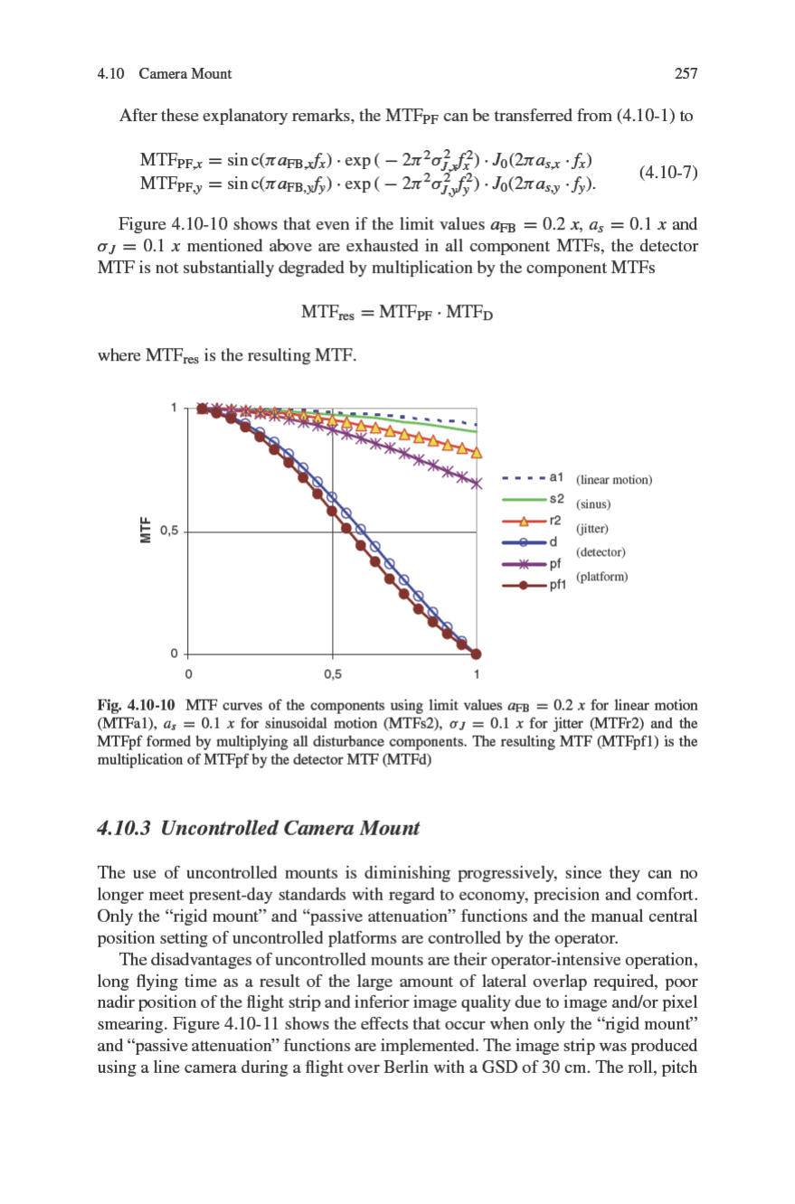
Attitude control can be dramatically improved with a digital airborne camera,
since it normally has an integrated POS, which can supply the mountwith attitude
values for all three axes and improve the attitude control by at least a factor of 10.
Image stabilisation is also improved, since the gyros provide much better interpo-
lation values. It can be seen in Fig. 4.10-12 that the “frayed” edges that occur with
uncontrolled platforms are absent in the corrected image strips (see Fig. 4.10-11).
Fig. 4.10-12 Rectified strips made with a controlled mounting platform
Chapter 5
Calibration
Since the effective resolution of classical airborne cameras and even more so
their radiometric performance were determined to a large extent by the film, these
cameras were calibrated with regard only to image geometry and the limit of res-
olution of the lens. In the case of digital cameras, however, a complete calibration
can be carried out at the system level, including effective resolution and spectral
responsivity.
Depending on the application of the camera, a calibration of various parame-
ters and quality standards is required, depending on not only users’ requirements
but also the guidelines of the certification authorities of the country concerned.
Whereas in the past, certification was required only for geometric calibration to
obtain an approval for a camera for surveying purposes, current requirements have
been extended to include radiometric parameters. The type of certification is also
undergoing changes. In the past, many countries relied on an accredited calibration
laboratory or set up their own calibration office for this purpose. A camera’s imag-
ing geometry was determined by measuring its essential components (lens, fiducial
marks, pressure plate).
Owing to the multitude of digital cameras and their complex internal struc-
tures, the classical procedure is seldom permitted anymore. The result is that in
most cases the entire system is calibrated. This is done in a laboratory, or by using
self-calibration after test flights in typical working conditions, or a combination
of the two. The situation concerning certification of camera systems is similar.
Increasingly, the requirement here is that the practical performance of a camera
be demonstrated on a flight over a test field.
5.1 Geometric Calibration
The purpose of geometric camera calibration is to establish an unequivocal relation-
ship between points on an image plane and the object space. Since in the case of an
aerial photograph, the position of the projection centre on the object side is virtu-
ally invariable, a much more simplified model than in the close-range case can be
used. It is only necessary to determine the position of the projection centre on the
261
R. Sandau (ed.), Digital Airborne Camera, DOI 10.1007/978-1-4020-8878-0_5,
C
Springer Science+Business Media B.V. 2010
262 5 Calibration
object side and the relationship between the point position in the image space and
the direction in the object space. For all other aerial image objects, this relationship
is unequivocal.
The model currently used to describe this relationship is that of a pinhole camera,
together with a method for correcting distortions in the image plane. But this is by
no means the most efficient representation for today’s digital evaluation, in which
a tabulation of the imaging directions, or at least of distortion corrections, is more
sensible for implementing optimum real-time transformations.
The development of classical airborne cameras and of the associated calibration
technology was closely linked to the capabilities of the devices used for restitu-
tion. In designing mechanical and optical analogue devices for restitution, it was
reasonable to implement the simplest possible model, namely that of the pinhole
camera. Every deviation from this model necessitated costly auxiliary constructions.
Consequently, great efforts were made to achieve an optimum geometric quality of
the imaging array. This related to the planeness of both the imaging medium − ini-
tially photographic plates and then a combination of a perfectly plane pressure plate
and plane film − and the lens, which, should have no worse defects than radially
symmetric distortion. In the final generation of airborne cameras, this objective was
achieved to perfection. Distortion was reduced to less than 2 μm and the pressure
plates ensured that the same degree of precision was achieved with respect to the
support plate of the film.
The calibration of a classical airborne camera comprises three parts, namely
ensuring the quality of the plane position, determination of the position of 4−8
fiducial marks and the main part, which is the determination of the imaging geom-
etry of the lens. This last requirement was usually limited to measuring the image
diagonals with the aid of goniometers (Bormann, 1975).
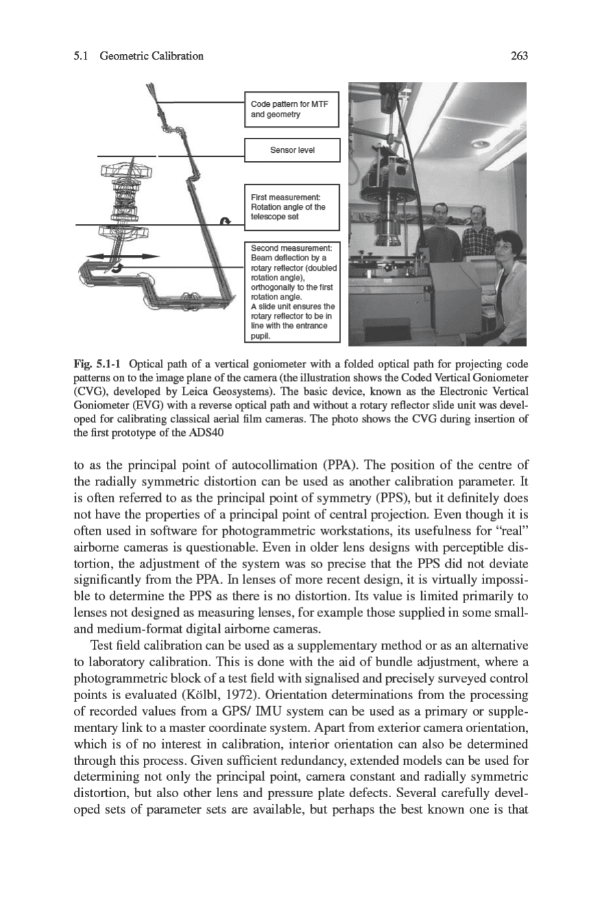
The optical path is reversed when measuring the lens, i.e., a measuring piece (a
pane of glass illuminated from behind) with a calibrated test pattern is used instead
of a system consisting of a pressure plate and film. A telescope set to infinity is
aimed at the patterns on the glass pane through the lens. The measured variable
is the angle of the telescope when pointing at the pattern element in question. An
example is shown in Fig. 5.1-1.
The horizontal goniometer − mechanically the simplest form of this device, in
which the camera lens is in a horizontal position and the axis of rotation in the
pupil on the object side in a vertical position − subsequently gave rise to vertical
goniometer systems in which the lens is tested in its operating position to avoid
deformations in the lens assembly. In addition, the type of measurement and its
evaluation were increasingly automated and improved.
The result of the measurement of a classical aerial film camera consists of the
camera constant and a radially symmetrical distortion. The camera constant is
selected to minimise the residual distortion.
The principal image point defined by a vertical line from the projection centre
on the image side to the image plane is designated as the reference point for image
evaluation. In practice, this point is determined through autocollimation of a reflec-
tion from the surface of the measuring piece and is consequently usually referred