Robertson C.R. Fundamental electrical and electronic principles
Подождите немного. Документ загружается.

Semiconductor Theory and Devices
271
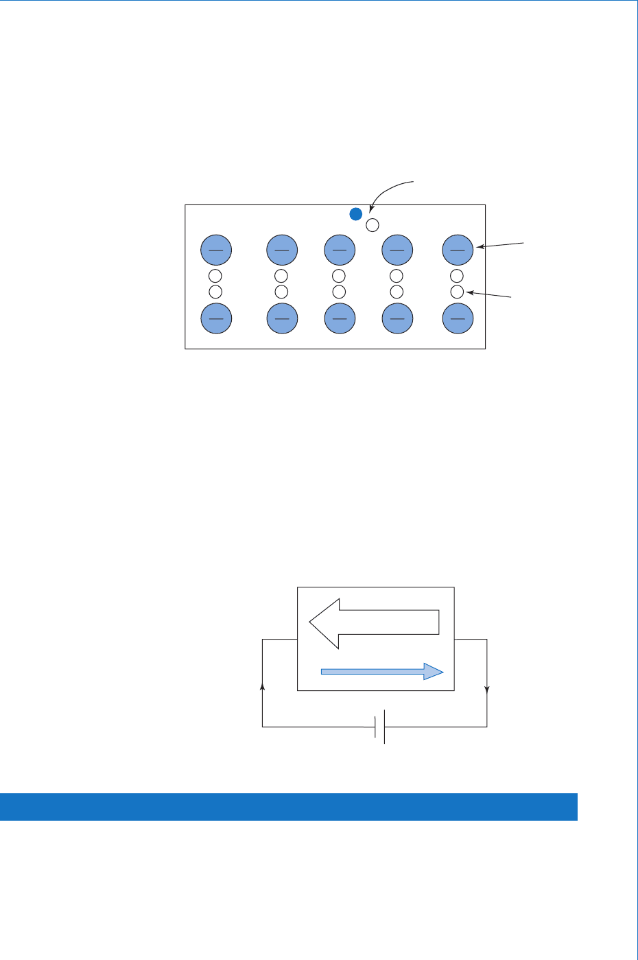
We now have the situation whereby there will be more mobile holes
than there are free electrons. Since holes are positive charge carriers,
and they will be in the majority, the doped material is called p-type
semiconductor, and it may be considered as consisting of a number
of fi xed negative ions and a corresponding number of mobile holes as
shown in Fig. 9.8 .
e–h pair
fixed
negative
ion
mobile
hole
Fig. 9.8
holes
electrons
I
Fig. 9.9
The circuit action when a battery is connected across the material is
shown in Fig. 9.9 . As the holes approach the left-hand end they are
fi lled by incoming electrons from the battery. At the same time, fresh
electron-hole pairs are generated; the electrons being swept to and
out of the right-hand end, and the holes drift to the left-hand end to
be fi lled. Once more, the current fl ow in the semiconductor is due to
the movement of holes and electrons in opposite directions, and only
electrons in the external circuit. As with the n-type material, p-type is
also electrically neutral.
9.8 The p-n Junction
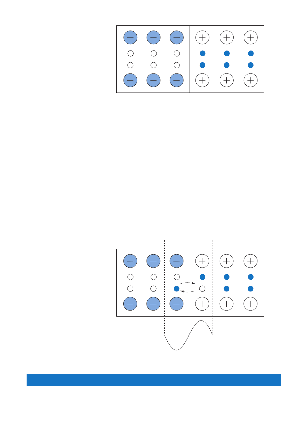
When a sample of silicon is doped with both donor and acceptor
impurities so as to form a region of p-type and a second region of
n-type material in the same crystal lattice , the boundary where the two
regions meet is called a p-n junction. This is illustrated in Fig. 9.10 .
272
Fundamental Electrical and Electronic Principles
Due to their random movement some of the electrons will diffuse
across the junction into the p-type, and similarly some of the holes will
diffuse across into the n-type. This effect is illustrated in Fig. 9.11 , and
from this fi gure it may be seen that region x acquires a net negative
charge whilst region y acquires an equal but positive net charge.
The region between the dotted lines is only about 1 m wide, and the
negative charge on x prevents further diffusion on electrons from the n-
type. Similarly the positive charge on y prevents further diffusion of holes
from the p-type. This redistribution of charge results in a potential barrier
across the junction. In the case of silicon this barrier potential will be
in the order of 0.6 to 0.7 V, and for germanium about 0.2 to 0.3 V. Once
again note that although there has been some redistribution of charge, the
sample of material as a whole is still electrically neutral (count up the
numbers of positive and negative charges shown in Fig. 9.11 ).
pn
Fig. 9.10
np
Charge
y
x
Fig. 9.11
9.9 The p-n Junction Diode
A diode is so called because it has two terminals: the anode, which
is the positive terminal, and the cathode, which is the negative
Semiconductor Theory and Devices
273
terminal. In the case of a p-n junction diode the anode is the p-type
and the cathode is the n-type. In Chapter 6 it was stated that a diode
will conduct in one direction but not in the other. This behaviour is
explained as follows.
9.10 Forward-biased Diode
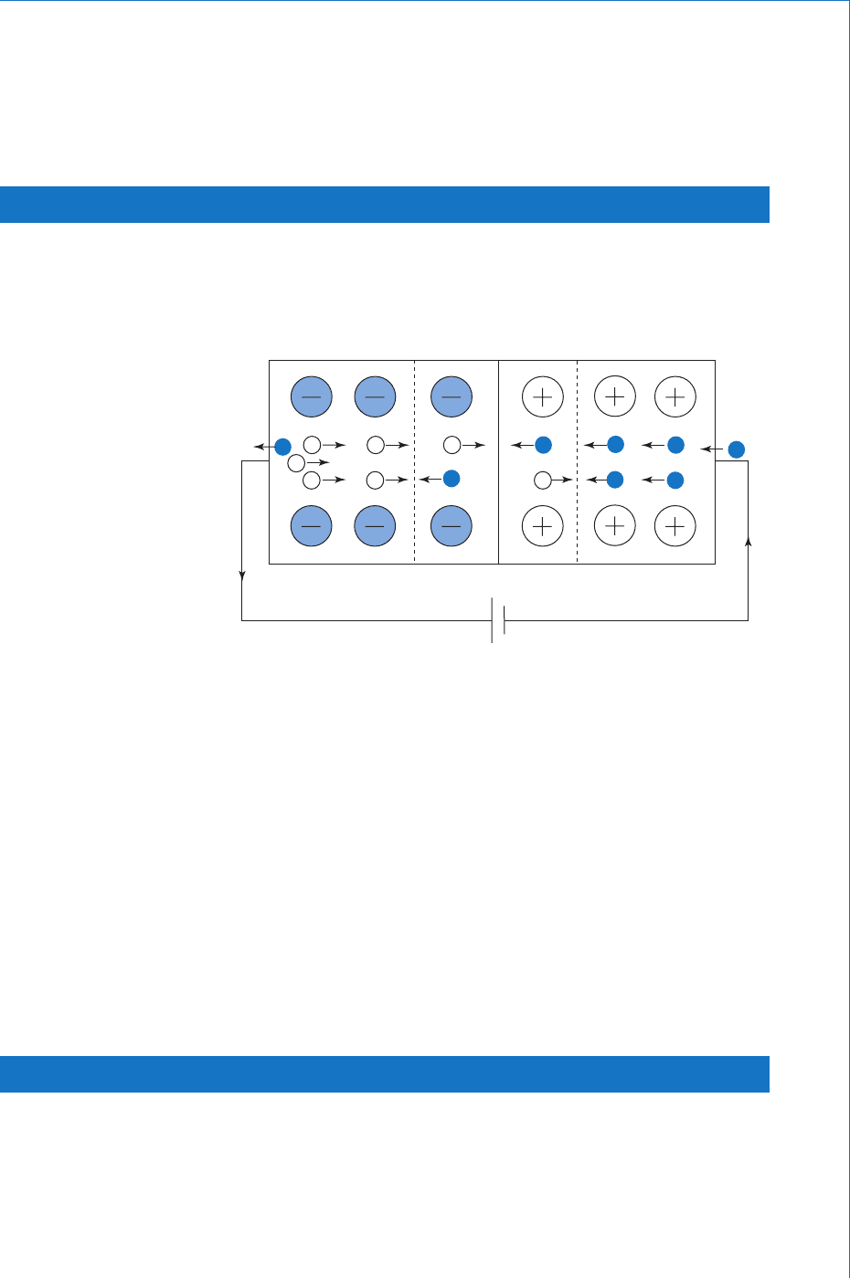
Figure 9.12 shows a battery connected across a diode such that the
positive terminal is connected to the anode and the negative terminal to
the cathode.
p n
Fig. 9.12
The electric fi eld produced by the battery will cause holes and
electrons to be swept toward the junction, where recombinations will
take place. For each of these an electron from the battery will enter the
cathode. This would have the effect of disturbing the charge balance
within the semicoductor, so to counterbalance this a fresh electron-hole
pair will be created in the p-type. This newly freed electron will then
be attracted to the positive plate of the battery, whilst the hole will be
swept towards the junction. Thus the circuit is complete, with electrons
moving through the external circuit, and a movement of holes and
electrons in the semiconductor. Hence, when the anode of the diode is
made positive with respect to the cathode it will conduct, and it is said
to be forward biased.
9.11 Reverse-biased Diode
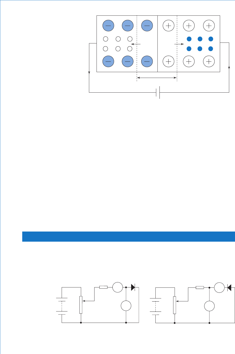
Consider what now happens when the battery connections are reversed
( Fig. 9.13 ). The electric fi eld of the battery will now sweep all the
mobile holes into the p-type and all the free electrons into the
n-type. This leaves a region on either side of the junction which has
been depleted of all of its mobile charge carriers. This layer thus acts
274
Fundamental Electrical and Electronic Principles
as an insulator, and is called the depletion layer. There has been a
redistribution of charge within the semiconductor, but since the circuit
has an insulating layer in it, current cannot fl ow. The diode is said to be
in its blocking mode.
However, there is no such thing as a perfect insulator, and the depletion
layer is no exception. Although all the mobile charge carriers provided
by the doping process have been swept to opposite ends of the
semiconductor, there will still be some thermally generated electron-hole
pairs. If such a pair is generated in the p-type region, the electron will be
swept across the junction by the electric fi eld of the battery. Similarly,
if the pair is generated in the n-type, the hole will be swept across the
junction. Thus a very small reverse current (in the order of microamps)
will fl ow, and is known as the reverse leakage current. Since this leakge
current is the result of thermally generated electron-hole pairs, then as
the temperature is increased so too will the leakage current.
9.12 Diode Characteristics
The characteristics of a device such as a diode can be best illustrated
by means of a graph (or graphs) of the current fl ow through it versus
applied voltage. Circuits for determining both the forward and reverse
characteristics are shown in Fig. 9.14 .
depletion
layer
pn
Fig. 9.13
A
R
RV1
(a) Forward bias
V
Fig. 9.14
A
R
RV1
(b) Reverse bias
V
Semiconductor Theory and Devices
275
Note the change of position of the voltmeter for the two different
tests. In (a) the voltmeter measures only the small p.d. across the
diode itself, and not any p.d. across the ammeter. In (b) the ammeter
measures only the leakage current of the diode, and does not include
any current drawn by the voltmeter. Ideally the voltmeter should not
draw any current at all, so it is recommended that a DVM is used rather
than a moving coil instrument such as an AVOmeter. The procedure
in each case is to vary the applied voltage, in steps, by means of RV1
and record the corresponding current values. When these results
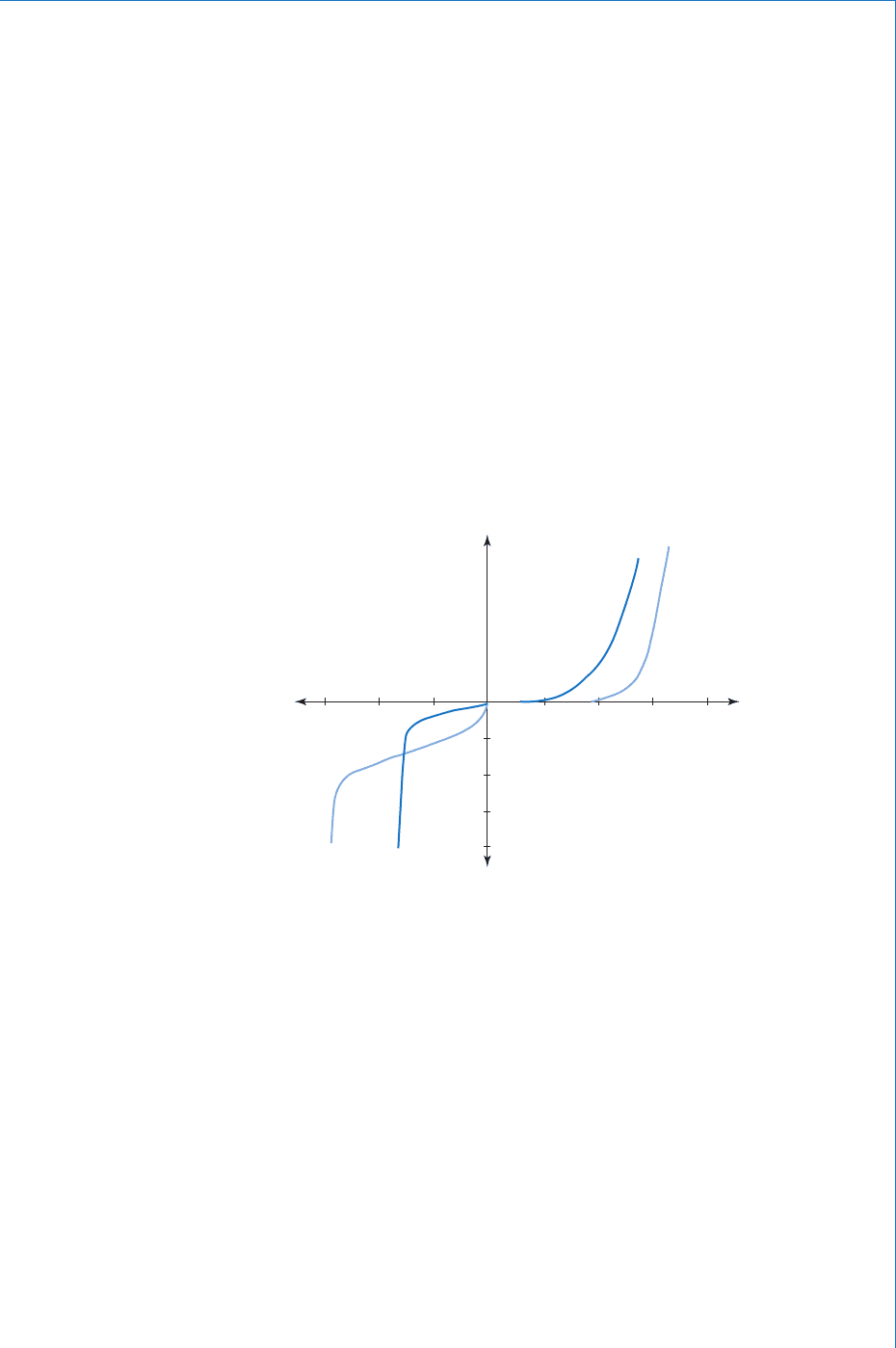
are plotted, for both silicon and germanium diodes, the graphs will
typically be as shown in Fig. 9.15 . The very different scales for both
current and voltage for the forward and reverse bias conditions should
be noted. Also, the actual values shown for the forward current scale
and the reverse voltage scale can vary considerably from those shown,
depending upon the type of diode being tested, i.e. whether it be a
small signal diode or a power rectifying diode. In the case of the latter,
the forward current would usually be in amperes rather than milliamps.
300
V
A
(V)
V
A
(V)
I
A
(μA)
I
A
(mA)
Si
Si
Forward
Ge
Ge
200 100
0
5
10
15
20
0.25 0.5 0.75 1.0
Fig. 9.15
The sudden increase in reverse current occurs at a reverse voltage
known as the reverse breakdown voltage. The effect occurs because the
intensity of the applied electric fi eld causes an increase in electron-hole
pair generation. These electron-hole pairs are not due to temperature,
but the result of electrons being torn from bonds by the electric fi eld.
This same fi eld will rapidly accelerate the resulting charge carriers and
as they cross the junction they will collide with atoms. These collisions
will free more charge carriers, and the whole process builds up very
rapidly. For this reason the effect is known as avalanche breakdown,
and will usually result in the destruction of the diode.
When the impurity doping of the semiconductor is heavier than ‘ normal ’ ,
the depletion layer produced is much thinner. In this case, when
breakdown occurs, the charge carriers can pass through the depletion
276
Fundamental Electrical and Electronic Principles
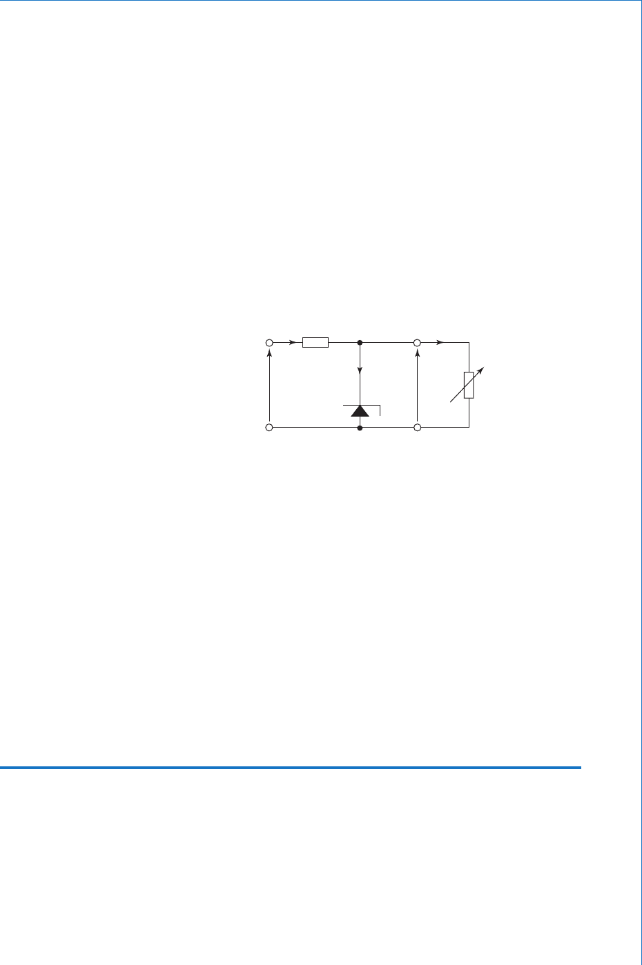
In Fig. 9.17 , V
Z
represents the zener breakdown voltage, and if it were
an ideal device, this p.d. across it would remain constant, regardless
of the value of current, I
Z
, fl owing through it. In practice the graph
will have a fairly steep slope as shown. The inverse of the slope of the
graph is defi ned as the diode slope resistance, r
Z
, as follows
r
V
I
Z
D
Z
ohm (9.1)
with very little chance of collisions taking place. This type of breakdown
is known as zener breakdown and such diodes are called zener diodes.
9.13 The Zener Diode
The main feature of the zener diode is its ability to operate in the
reverse breakdown mode without sustaining permanent damage. In
addition, during manufacture, the precise breakdown voltage (zener
voltage) for a given diode can be predetermined. For this reason they
are also known as voltage reference diodes. The major application for
these devices is to limit or stabilise a voltage between two points in a
circuit. Diodes are available with zener voltages from 2.6 V to about
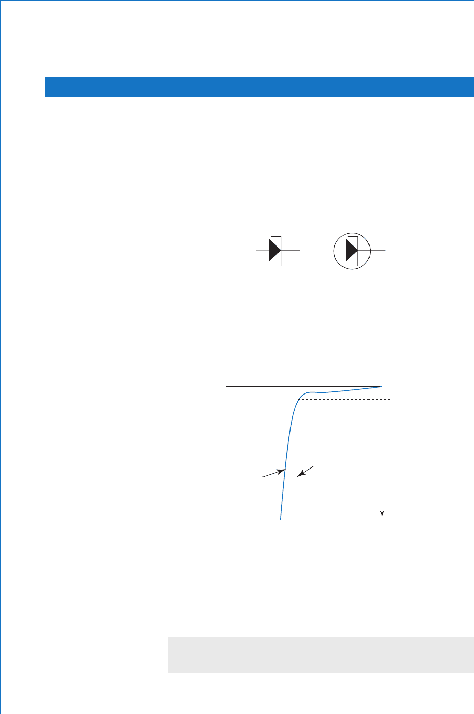
200 V. The circuit symbol for a zener diode is shown in Fig. 9.16 .
or
Fig. 9.16
The forward characteristic for a zener diode will be the same as for any
other p-n junction diode, and also, since the device is always used in its
reverse bias mode, only its reverse characteristic need be considered.
Such a characteristic is shown in Fig. 9.17 .
V
D
(V)
I
Z
(min)
I
Z
(mA)
V
Z O
ideal
actual
Fig. 9.17
Semiconductor Theory and Devices
277
Typical values for r
Z
range from 0.5 to about 150 . For satisfactory
operation the current through the diode must be at least equal to I
Z(min)
.
Due to the diode slope resistance, the p.d. across the diode will vary by
a small amount from the ideal of V
Z
volt as the diode current changes.
For example, if r
Z
1 and V
Z
15 V, a change in diode current of
30 mA would cause only a 0.02% change in the diode p.d. This fi gure
may be verifi ed by applying equation (9.1).
The value of current that may be allowed to fl ow through the device
must be limited so as not to exceed the diode power rating. This power
rating is always quoted by the manufacturer, and zener diodes are
available with power ratings up to about 75 W .
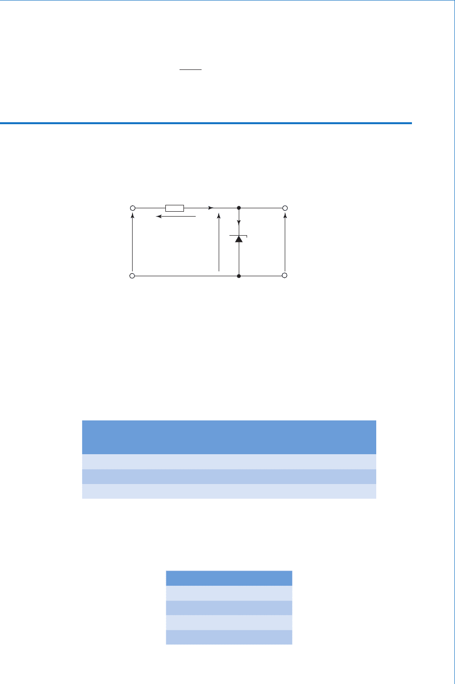
Consider now the application of a zener diode to provide simple
voltage stabilisation to a load. A circuit is shown in Fig. 9.18 .
R
S
R
L
I
L
I
S
I
Z
V
Z
V
o
V
Fig. 9.18
In order for satisfactory operation the supply voltage, V
S
, needs to be
considerably greater than the voltage required at the load. The purpose
of the series resistor R
S
is to limit the maximum diode current to a
safe value, bearing in mind the diode ’ s power rating. Considering
Fig. 9.18 , the diode current will be at its maximum when the load is
disconnected, because under this condition all of the current from
the supply will fl ow through the diode, i.e. I
Z
I
S
. When the load is
connected it will draw a current I
L
, and since I
Z
I
S
– I
L
, then under
this condition the diode current will decrease, since it must divert
current to the load. The output voltage, however, will remain virtually
unchanged. Knowing the diode power rating a suitable value for R
S
may be calculated as shown in the following worked example. This
example also demonstrates the stabilising action of the circuit.
Worked Example 9.1
Q A 9 . 1 V, 500 mW zener diode is used in the circuit of Fig. 9.18 to supply a 2.5 k load. The diode has a
slope resistance of 1. 5 , and the input supply has a nominal value of 12 V .
(a) Calculate a suitable value for the series resistor R
s
.
(b) Calculate the value of diode current when the load resistor is connected to the circuit.
(c) If the input supply voltage decreases by 10%, calculate the percentage change in the p.d. across
the load.

278
Fundamental Electrical and Electronic Principles
A
V
Z
9.1 V ; P
Z
0.5 W; r
Z
1. 5 ; V 12 V ; R
L
2500
(a)
PV
P
V
ZZZ
Z
Z
Z
ZS
I
I
II
watt
amp
so, mA
05
9
54 95
.
.
.
1
( I
S
I
Z
because for this condition the load is disconnected)
VVV
V
R
V
R
SZ
S
S
S
S
S
volt
V
ohm
11
1
29
29
29
54 95 0
52 78
3
.
.
.
.
.
I
A resistor of this precise value would not be readily available, so the nearest
preferred value resistor would be chosen. However, to ensure that the
diode power rating cannot be exceeded, the nearest preferred value greater
than 52.78 would be chosen. Thus a 56 resistor would be chosen.
In order to protect the resistor, its own power rating must be taken into
account. In this circuit, the maximum power dissipated by R
S
is:
P
max
I
S
2
R
S
watt (54.95 10
3
)
2
56
P
max
0 . 169 W, so a 0.25 W resistor would be chosen,
and the complete answer to part (a) is:
R
S
should be a 56 , 0.25 W resistor Ans
(b) With R
L
2500 and V
o
9.1 V
I
I
III
I
L
o
L
L
ZSL
Z
V
R
amp
mA
amp ( ) mA
9
25 10
364
55 3 64
5
3
.
.
.
.
1
11.36 mA Ans
(c) When V falls by 10% from its nominal value, then
V
V
VV
R
S
Z
S
12 0 2 2 2
08
08 9
56
()
hence, V
amp
..
.
..
11 1 1
1
11
I
I
SS
30 36.mA
The current for the load must still be diverted from the diode, so
III
ZSL
amp ( ) mA mA30 36 3 64 26 72.. .
therefore, ( ) mA mA, and from equation I
Z
5 36 2672 24641.. . (():
volt
V
11
11
0
24 64 0 5
0 037
3
.
..
.
Vr
V
ZZZ
Z
I
Semiconductor Theory and Devices
279
Thus the voltage applied to the load changes by 0.037 V, which expressed
as a percentage change is:
change
change % (compared with a % c
0 037
9
00
04 0
.
.
.
1
1
11Ans hhange in suppl
y
)
Worked Example 9.2
Q A d.c. voltage of 15 V 5% is required to be supplied from a 24 V unstabilised source. This is to be
achieved by the simple regulator circuit of Fig. 9.19 .
R
S
V
S
V
Z
I
Z
I
S
V
o
24 V
0 V
V
Fig. 9.19
The available diodes and resistors are listed below.
(a) For each diode listed determine the appropriate resistor required and hence determine the total
unit cost for each circuit.
(b) In order to satisfy the speci ed output voltage tolerance of 5%, determine which of the three
circuits will meet the speci cation at lowest cost.
Diode
No.
V
Z
(V) Slope
resistance ( )
Max power
(W)
Unit
cost (£)
1 15 30 0.5 0.07
2 15 15 1.3 0.20
3 15 2.5 5.0 0.67
Resistors are available in the following values and unit costs
18, 27, 56, 100, 120, 150, 220, 270, and 330
0.25 W £0.026
0.5 W £0.038
1.0 W £0.055
2.5 W £0.260
7.5 W £0.280

280
Fundamental Electrical and Electronic Principles
A
(a)
For all three diodes:
V
S
( V V
Z
) volt 24 15 9 V
Diode :
amp
mA
1
1
I
I
Z
Z
Z
Z
P
V
05
5
33 3
.
.
R
V
R
S
S
Z
S
I
ohm
9
33 3 0
270
3
. 1
P
V
R
P
S
S
S
S
2
8
270
03
watt
W
1
.
and, R
S
270 , 0.5 W Ans
total unit cost £(0.07 0.038) £0.045 Ans
Diode 2:
I
Z
1
1
.
.
3
5
86 7 amp mA
R
P
S
S
9
86 7 0
03 85
8
2
3
.
.
1
11
1
1
, so choose the 20 resistor
00
0 675 . W, so choose .0 W rating1
hence, R
S
12 0 , 1.0 W Ans
total unit cost £(0.20 0.055) £0.26 Ans
Diode 3:
I
Z
5
5
333 3
1
. mA
R
P
S
S
9
333 3 0
27
8
27
375
3
.
.
1
1
W so choose W resistor
hencee, , W R
S
27 7 5 . Ans
total unit cost £ (0.67 0.28) £0.95 Ans
(b)
Allowable VV
Z
55
00
075
1
1
.
Diode : volt V, which is unaccept11V
Zzrz
I 30 0 30 0 9
3
.aable
Diode : V, which is acceptable
Dio
23005045
3
V
Z
11.
dde : V, which is acceptable3 30 0 25 0075
3
V
Z
1 ..
Thus to meet the speci cation at lowest cost, circuit 2 would be adopted Ans
