Robertson C.R. Fundamental electrical and electronic principles
Подождите немного. Документ загружается.

D.C. Machines
241
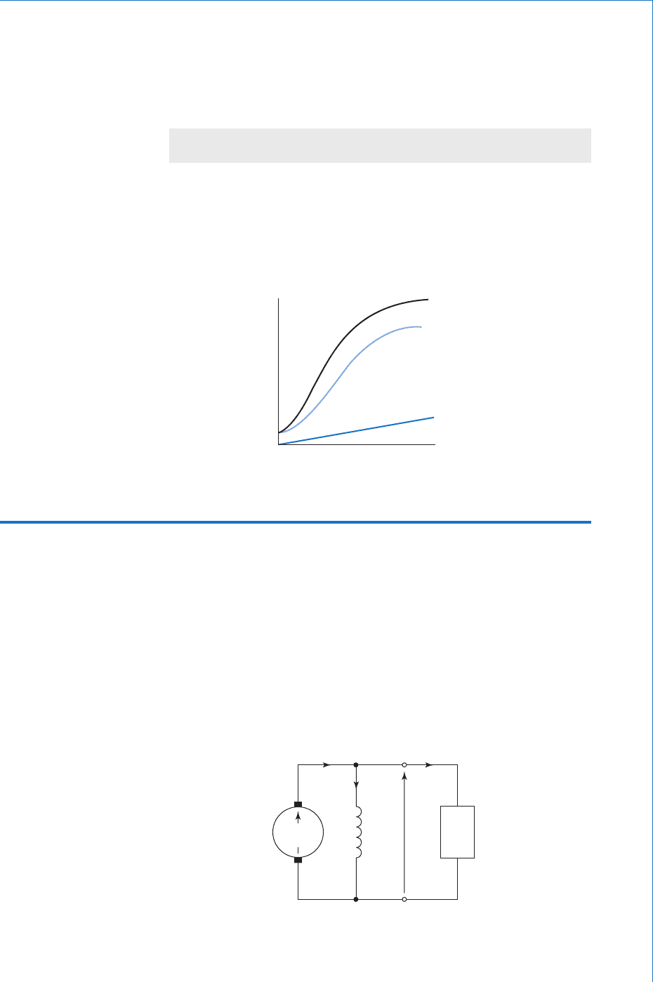
shown in Fig. 7.12 , and from this it may be seen that the armature has
to supply current to both the load and the fi eld, such that:
III
aLf
amp
(7.2)
I
a
I
f
I
L
R
a
R
f
R
L
EV
S
Fig. 7.12
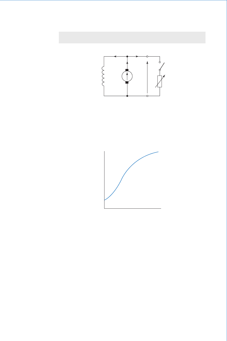
This self-excitation process can take place only if there is some
residual fl ux in the poles, and if the resistance of the fi eld circuit is
less than some critical value. The open-circuit characteristic is
illustrated in Fig. 7.13 .
0
E
I
f
Fig. 7.13
The resistance of the fi eld winding, R
f
, is constant and of a relatively
high value compared with R
a
. Typically, I
f
will be in the order of 1A
to 10A, and will remain reasonably constant. The shunt machine is
therefore considered to be a constant-fl ux machine. When switch
S is closed, the armature current will increase in order to supply the
demanded load current, I
L
. Thus I
a
I
L
, and as the load current is
increased, so the terminal voltage will fall, according to the equation,
V E I
a
R
a
volt. The output characteristic will therefore follow
much the same shape as that for the separately excited generator and
is shown in Fig. 7.14 . This condition applies until the machine is
providing its rated full-load output. If the load should now demand
even more current, i.e. the machine is overloaded, the result is that the
generator simply stops generating. This effect is shown by the dotted
lines in the output characteristics.

242
Fundamental Electrical and Electronic Principles
The shunt generator is the most commonly used d.c. generator, since it
provides a reasonably constant output voltage over its normal operating
range. Its other obvious advantage is the fact that it is self-exciting,
and therefore requires only some mechanical means of driving the
armature.
7.7 Series Generator
In this machine the fi eld winding is connected in series with the
armature winding and the load, as shown in Fig. 7.15 . In this case,
I
L
I
a
I
f
, so this is a variable-fl ux machine. Since the fi eld winding
must be capable of carrying the full-load current (which could be
in hundreds of amps for a large machine), it is usually made from a
few turns of heavy gauge wire or even copper strip. This also has the
advantage of offering a very low resistance. This generator is a self-
excited machine, provided that it is connected to a load when started.
Note that a shunt generator will self-excite only when disconnected
from its load.
When the load on a series generator is increased, the fl ux produced will
increase, in almost direct proportion. The generated emf will therefore
voltage
E
V
0
I
L
I
a
R
a
full-load
Fig. 7.14
I
a
R
a
R
L
I
L
R
f
I
f
I
a
I
f
I
L
V
E
Fig. 7.15
D.C. Machines
243
increase with the demanded load. The increase of fl ux, and hence
voltage, will continue until the onset of magnetic saturation, as shown
in the output characteristic of Fig. 7.16 . The terminal voltage is related
to the emf by the equation:
VEIR R
aa f
( )volt
(7.3)
The variation of terminal voltage with load is not normally a
requirement for a generator, so this form of machine is seldom used.
However, the rising voltage characteristic of a series-connected
fi eld winding is put to good use in the compound machine, which is
described in Further Electrical and Electronic Principles .
I
a
P
o
R
a
I
L
I
f
R
f
200 Ω
V
450V
80
kW
E
475V
Fig. 7.17
emf
0 I
L
I
a
(R
a
R
f
)
E
V
Fig. 7.16
Worked Example 7.1
Q The resistance of the eld winding of a shunt generator is 200 . When the machine is delivering
80 kW the generated emf and terminal voltage are 475 V and 450 V respectively. Calculate (a) the
armature resistance, and (b) the value of generated emf when the output is 50 kW, the terminal
voltage then being 460 V.
A
R
f
200 ; P
o
80 10
3
watt; V 450 V; E 475 V
The circuit diagram is shown in Fig. 7.17 . It is always good practice to sketch the
appropriate circuit diagram when solving machine problems.

244
Fundamental Electrical and Electronic Principles
(a)
PV
P
V
V
R
oL L
o
L
f
II
I
I
watt; so amp
therefore A
80 0
450
77 8
3
1
1 .
ff
aLf
aa
REV
amp A
amp A
volt
450
200
225
80 05
475 450
.
.III
I
1
225
25
80 05
0 139
V
therefore ohmR
a
1 .
. Ans
(b)
When W, V
thus A
PV
V
R
o
L
f
f
50 0 460
50 0
460
08 7
460
2
3
3
1
1
1I
I
.
000
23
08 7 2 3
460 0 13
.
..
.
A
hence, A
volt (
I
I
a
aa
EV R
1 111
111 99
475 4
)
therefore V E . Ans
Note : Although the load had changed by about 60%, the eld current has
changed by only about 2.2%. This justi es the statement that a shunt generator
is considered to be a constant- ux machine.
7.8 D.C. Motors
All of the d.c. generators so far described could be operated as motors,
provided that they were connected to an appropriate d.c. supply. When
the machine is used as a motor, the armature generated emf is referred
to as the back-emf, E
b
, which is directly proportional to the speed of
rotation. However, the speed is inversely proportional to the fi eld fl ux .
In addition, the torque produced by the machine is proportional to both
the fl ux and the armature current. Bearing these points in mind, we can
say that:
Speed,
E
b
(7.4)
and torque, TI
a
(7.5)
7.9 Shunt Motor
When the machine reaches its normal operating temperature, R
f
will
remain constant. Since the fi eld winding is connected directly to a
D.C. Machines
245
fi xed supply voltage, V volt, then I
f
will be fi xed. Thus, the shunt
motor ( Fig. 7.18 ) is a constant-fl ux machine.
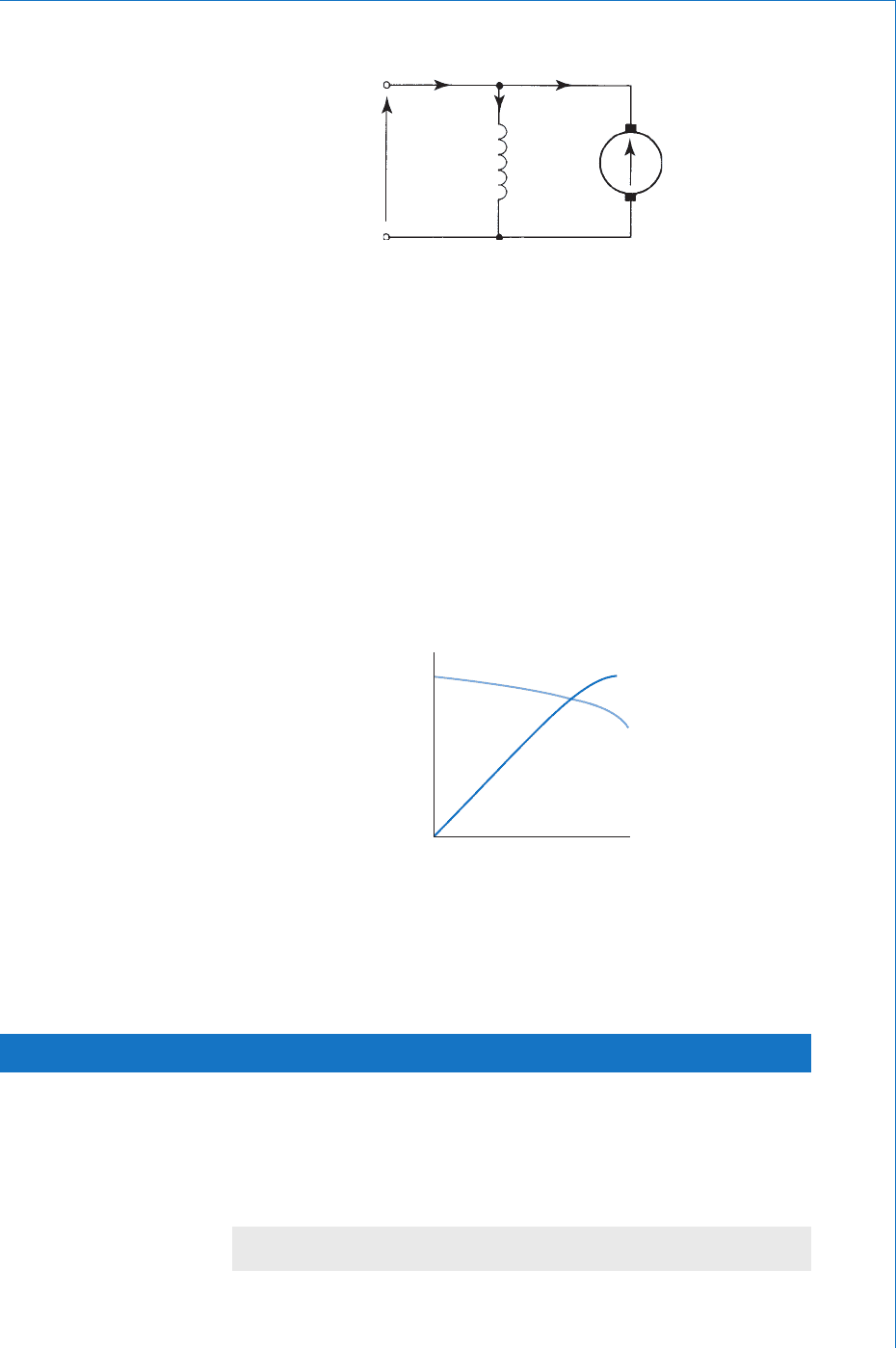
As the back-emf will have the same shape graph as that for the
generator emf, and using (7.4) and (7.5) the graphs of speed and torque
versus current will be as in Fig. 7.19 . Note that when the machine
is used as a motor, the supply current is identifi ed as I
L
. In this case,
the subscript ‘ L ’ represents the word ‘ line ’ . Thus I
L
identifi es the line
current drawn from the supply, and I
a
is directly proportional to I
L
.
I
f
R
f
R
a
I
a
I
L
E
b
V
Fig. 7.18
speed or
torque
0 I
L
T
ω
Fig. 7.19
Shunt motors are used for applications where a reasonably constant
speed is required, between no-load and full-load conditions.
7.10 Series Motor
Like the series generator, this machine is a variable-fl ux machine.
Despite this, the back-emf of this motor remains almost constant,
from light-load to full-load conditions. This fact is best illustrated by
considering the circuit diagram ( Fig. 7.20 ), with some typical values.
EVIRR
baaf
( ) volt
(7.6)
246
Fundamental Electrical and Electronic Principles
Let us assume the following: V 200 V; R
a
0.15 ; R
f
0.03 ;
I
a
5 A on light-load; I
a
50 A on full-load
Light-load: ( ) V
Full-load:
E
E
b
b
200 5 0 15 0 03 199 1
200 50
.. .
(()V0 15 0 03 191..
From the above fi gures, it may be seen that although the armature
current has increased tenfold, the back-emf has decreased by only 4%.
Hence, E
b
remains sensibly constant.
Since E
b
/ , and E
b
is constant, then:
1
1...............[ ]
Similarly, T I
a
, and since I
a
until the onset of magnetic
saturation,
then ............................ .....[2]
and after s
TI
a
2
.
aaturation, ................[ ]TI
a
3
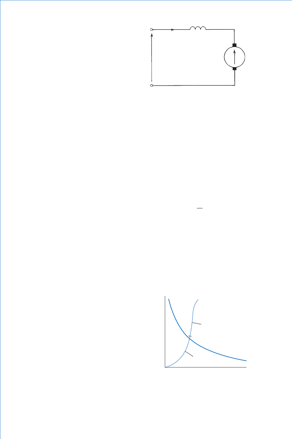
Using [1] to [3] above, the speed and torque characteristics shown in
Fig. 7.21 may be deduced.
V
R
a
E
b
R
f
I
L
I
a
Fig. 7.20
speed or
torque
T
ω
T I
2
a
T I
a
0
I
L
Fig. 7.21
Note: From the speed characteristic it is clear that, on very light loads,
the motor speed would be excessive. Theoretically, the no-load speed

D.C. Machines
247
would be infi nite! For this reason a series motor must NEVER be
started unless it is connected to a mechanical load suffi cient to prevent
a dangerously high speed. Similarly, a series motor must not be used to
operate belt-driven machinery, lifting cranes etc., due to the possibility
of the load being suddenly disconnected. If a series motor is allowed
to run on a very light load, its speed builds up very quickly. The
probable outcome of this is the distintegration of the machine, with the
consequent dangers to personnel and plant.
The series motor has a high starting torque due to the ‘ square-law ’
response of the torque characteristic. For this reason, it tends to be
used mainly for traction purposes. For example, an electric train engine
requires a very large starting torque in order to overcome the massive
inertia of a stationary train.
Summary of Equations
Generators:
Shunt generator: I
a
I
L
I
f
amp
VEIR
aa
volt
Series generator: I
a
I
L
I
f
amp
VEIR R
aa f
( ) volt
Motors:
Shunt motor: E
b
V I
a
R
a
volt
Series motor: E
b
V I
a
(R
a
R
f
) volt
Speed equation:
n
EE
bb
rev/second; or rad/second
Torque equation: T I
a
newton metre

248 Fundamental Electrical and Electronic Principles
Assignment Questions
1 A shunt generator supplies a current of
85 A at a terminal p.d. of 380 V. Calculate
the generated emf if the armature and eld
resistances are 0.4 . and 95 respectively.
2 A generator produces an armature current of
50 A when generating an emf of 400 V. If the
terminal p.d. is 390 V, calculate (a) the value
of the armature resistance, and (b) the power
loss in the armature circuit.
3 A d.c. shunt generator supplies a 50 kW load
at a terminal voltage of 250 V. The armature
and eld circuit resistances are 0.15 and
5 0 respectively. Calculate the generated
emf.

D.C. Transients
Chapter 8
Learning Outcomes
This chapter explains the response of capacitor-resistor, and inductor-resistor circuits, when
they are connected to and disconnected from, a d.c. supply.
On completion of this chapter you should be able to:
1 Show how the current and capacitor voltage in a series C-R circuit varies with time, when
connected to/disconnected from a d.c. supply.
2 Show how the current through, and p.d. across an inductor in a series L-R circuit varies with
time, when connected to/disconnected from a d.c. supply.
3 D e fi ne the term time constant for both types of above circuits.
249
8.1 Capacitor-Resistor Series Circuit (Charging)
Before dealing with the charging process for a C-R circuit, let us
fi rstly consider an analogous situation. Imagine that you need to infl ate
a ‘ fl at ’ tyre with a foot pump. Initially it is fairly easy to pump air
into the tyre. However, as the air pressure inside the tyre builds up,
it becomes progressively more diffi cult to force more air in. Also, as
the internal pressure builds up, the rate at which air can be pumped
in decreases. Comparing the two situations, the capacitor (which is to
be charged) is analogous to the tyre; the d.c. supply behaves like the
pump; the charging current compares to the air fl ow rate; and the p.d.
developed between the plates of the capacitor has the same effect as
the tyre pressure. From these comparisons we can conclude that as the
capacitor voltage builds up, it reacts against the emf of the supply, so
slowing down the charging rate. Thus, the capacitor will charge at a
non-uniform rate, and will continue to charge until the p.d. between its
plates is equal to the supply emf. This last point would also apply to
tyre infl ation, when the tyre pressure reaches the maximum pressure
available from the pump. At this point the air fl ow into the tyre would
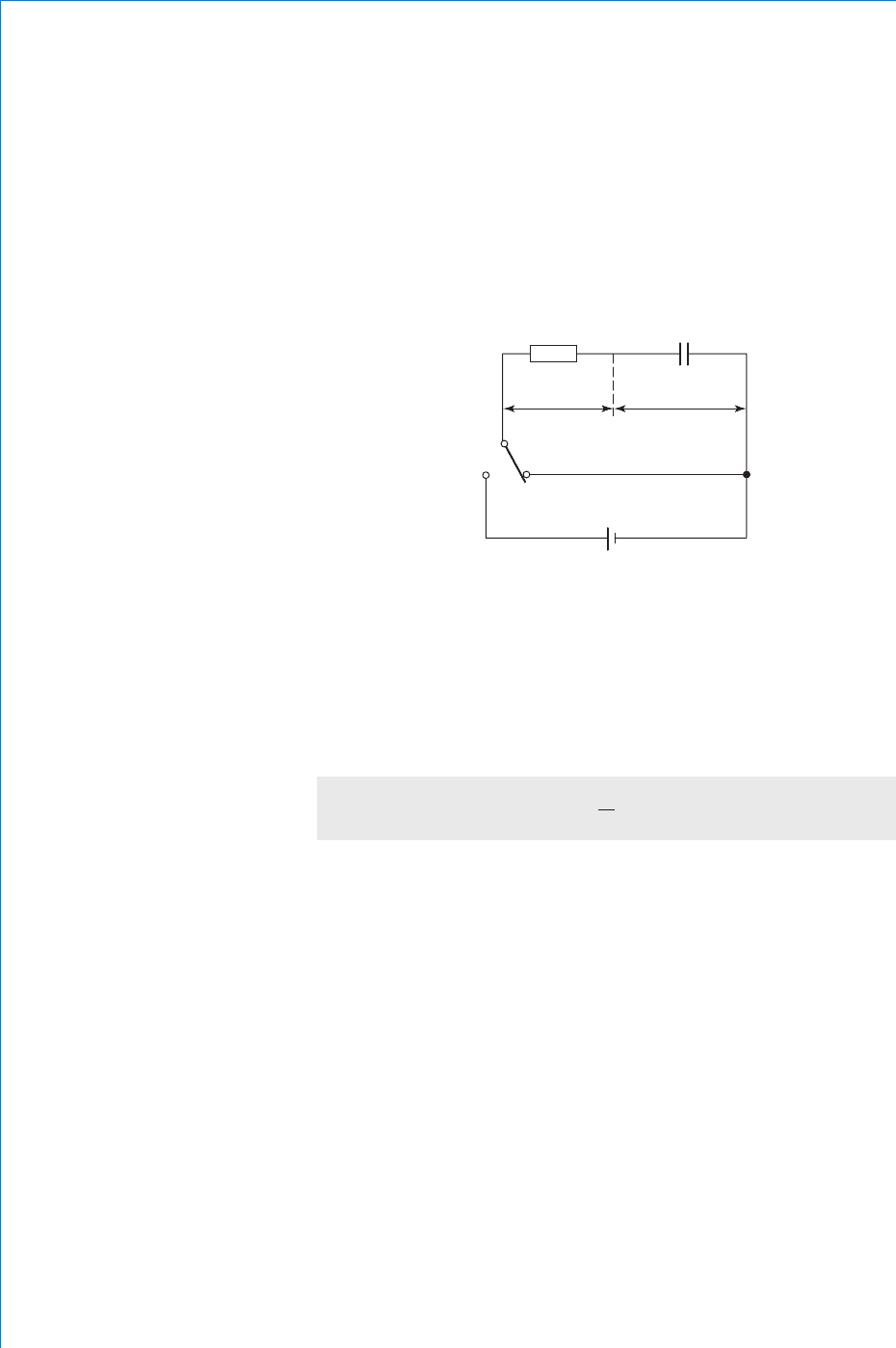
250
Fundamental Electrical and Electronic Principles
cease. Similarly, when the capacitor has been fully charged, the
charging current will cease.
Let us now consider the C-R charging circuit in more detail. Such a
circuit is shown in Fig. 8.1 . Let us assume that the capacitor is initially
fully discharged, i.e. the p.d. between its plates ( v
C
) is zero, as will be
the charge, q. Note that the lowercase letters v and q are used because,
during the charging sequence, they will have continuously changing
values, as will the p.d. across the resistor (v
R
) and the charging current,
i. Thus these quantities are said to have transient values.
RC
V
R
V
C
‘B’ ‘A’
E
i
Fig. 8.1
At some time t 0, let the switch be moved from position ‘ A ’ to
position ‘ B ’ . At this instant the charging current will start to fl ow.
Since there will be no opposition offered by capacitor p.d. (v
C
0),
then only the resistor, R, will offer any opposition. Consequently, the
initial charging current ( I
0
) will have the maximum possible value for
the circuit. This initial charging current is therefore given by:
I
E
R
0
amp
(8.1)
Since we are dealing with a series d.c. circuit, then the following
equation must apply at all times:
Ev v
RC
volt...............[ ]1
thus, at time t 0
Ev
R
0
i.e. the full emf of E volt is developed across the resistor at the instant
the supply is connected to the circuit. Since v
R
iR, and at time t 0,
i I
0
, this confi rms equation (8.1) above.
Let us now consider the situation when the capacitor has reached its
fully-charged state. In this case, it will have a p.d. of E volt, a charge of
Q coulomb, and the charging current, i 0. If there is no current fl ow
then the p.d. across the resistor, v
R
0, and eqn [1] is:
Ev
C
0
