Pumping Station Desing - Second Edition by Robert L. Sanks, George Tchobahoglous, Garr M. Jones
Подождите немного. Документ загружается.

Admittance
Probes
The
admittance system
is a
modern improved version
of
the
older capacitance probe.
It
consists
of a
slender,
usually
Teflon®-coated
rod
that extends into
the
mon-
itored liquid.
The rod is
excited with
a
low-power,
high-frequency
voltage.
An
electrical
current
flows
between
the rod and a
ground reference, which
may
be
either
the fluid
itself
(if it is a
conductor)
or a
ground plane
on the
wall
of the
tank
(if the fluid is
essentially
a
nonconductor).
The
current
flow
varies
as
the fluid
level changes
and
provides
a
measurement
of
the
tank level.
The
system
is
totally solid state, which
produces neither motion
nor
mechanical
force.
Solid-
state systems
are
most
useful
where
a
transmitted sig-
nal is
required. They
do not
produce
a
direct mechani-
cal
readout,
but
they
can be fitted
with
a
local
electronic
indicator
to
display
the
level.
Ultrasonic
Measurement
The
ultrasonic level measurement system consists
of a
transducer (suspended above
the fluid) and
associated
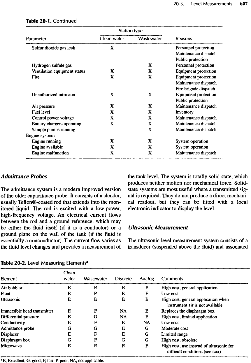
Table
20-1.
Continued
Station
type
Parameter
Clean
water
Wastewater
Reasons
Sulfur
dioxide
gas
leak
X
Personnel protection
Maintenance dispatch
Public protection
Hydrogen
sulfide
gas X
Personnel protection
Ventilation
equipment status
X X
Equipment protection
Fire
X X
Equipment protection
Maintenance dispatch
Fire brigade dispatch
Unauthorized intrusion
X X
Equipment protection
Public protection
Air
pressure
X X
Maintenance dispatch
Fuel level
X X
Inventory
Control power voltage
X X
Maintenance dispatch
Battery
chargers operating
X X
Maintenance dispatch
Sample pumps running
X
Maintenance dispatch
Engine systems
Engine
running
X X
System operation
Engine available
X X
System operation
Engine
malfunction
X X
Maintenance dispatch
Table
20-2.
Level
Measuring
Elements
3
Clean
Element
water
Wastewater
Discrete
Analog
Comments
Air
bubbler
EE
EE
High
cost,
general application
Float
EP
EF
Low
cost
Ultrasonic
EE
EE
High
cost,
general application when
instrument
air is not
available
Immersible
head transmitter
E F NA E
Replaces
the
diaphragm
box
Differential
pressure
E G NA E
High cost, limited application
Conductivity
EF
E NA
Low
cost
Admittance probe
GG
EG
Moderate cost
Displacer
EF
EG
Limited range
Diaphragm
box
GF
GG
High cost,
obsolete
Microwave
EE
EE
High cost,
use
instead
of
ultrasonic
for
difficult
conditions
(see
text)
a
E,
Excellent;
G.
good;
F,
fair;
P.
poor,
NA, not
applicable.
electronics.
The
transducer periodically emits
a
pulse
of
sonic energy toward
the
liquid,
and the
pulse
is
reflected
by the
liquid
surface
back
to the
transducer.
The
transit time
of
this pulse
is
approximately propor-
tional
to the
distance between
the
transducer
and the
liquid
surface.
The
speed
of the
sonic pulse
is
affected
by
the
density
of the gas
above
the
liquid and,
hence,
by
both barometric pressure
and
temperature. Good-qual-
ity
ultrasonic level systems
are
fully
compensated
and
provide very accurate level measurement.
But
many
systems
are
either uncompensated
or
only temperature
compensated
and
cannot measure with accuracy. Read-
ings
may
also
be
affected
by
foam,
which causes either
a
false
reflection
or a
loss
of
reflection. Discontinuities
in
the
vessel walls
may
also cause
false
reflections.
The
better quality ultrasonic level systems have
microprocessors that reject spurious reflections. Never-
theless, when applying ultrasonic level measuring
devices, check
the
angle
of the
emitted sonic pulse
to
ensure that
the
space within
the
transmission cone
is
clear
of
obstructions. Manufacturers rate ultrasonic
level transducers
for
operation
from
- 40 to
+9O
0
C
(-40
to
+20O
0
F),
but field
installations have
not
been satis-
factory
below
freezing
or in
windy
locations.
The
ultra-
sonic system
is
totally solid state
and
does
not
provide
a
direct mechanical indication
of
level.
Modern microprocessor-based ultrasonic level sys-
tems
are
accurate
and
reliable.
They have supplanted
bubbler systems
in
many facilities where maintenance
of
instrument
air
supply equipment
has
become
uneconomical
or
onerous.
Microwave
The
microwave level measurement system
is
similar
to the
ultrasonic, except that
a
microwave frequency
pulse
is
emitted toward
the
liquid surface. Microwave
pulses penetrate
foam,
and the
speed
of
microwaves
is
affected
very
little
by the
density
of the gas
above
the
liquid
or by
very
low or
high temperatures. Thus,
although
considerably more expensive than
the
ultra-
sonic system,
the
microwave system operates reliably
under
much more
difficult
conditions.
lmmersible
Head
Transmitter
Immersible electronic head transmitters
are
designed
to be
completely immersed
in the
liquid being moni-
tored.
A
cable containing both
the
signal leads
and a
pressure reference tube connects
the
transmitter
to a
junction
box
above
the
vessel
or
channel.
The
pressure
element
is
typically
the
strain gauge type
described
under pressure transmitter.
Immersible
head transmit-
ters were originally designed
for oil field
borehole
use. They
are
economical, rugged,
and
reliable.
They
are
cylindrical
in
shape,
and
some users drop them
into
the
liquid through
a
pipe such that
the
sensing
diaphragm, which
forms
the
bottom
end to the
trans-
mitter,
is flush
with
the
bottom
of the
pipe.
This con-
venient installation
protects
the
transmitter
from
gross
solids present
in
wastewater applications. These units
have
been used
as a
complete replacement
for air
bub-
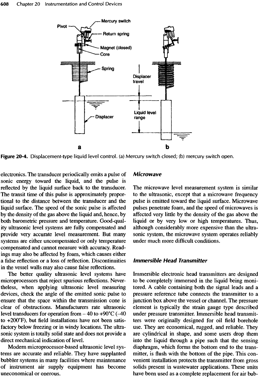
Figure
20-4.
Displacement-type
liquid
level
control,
(a)
Mercury
switch
closed;
(b)
mercury
switch
open.
biers in clean water applications. However, the typical
size
(25 mm or 1
in.)
is not
suitable
for
narrow spans
(less than
700 mm or 2.3
ft). With 75-mm (3-in.) dia-
phragms, they
can be
used
for
controlling
V/S
pumps
where
narrow spans
are
required. With reasonable fre-
quency
of
cleaning, they
are
suitable
for
wastewater
applications
if the
enclosing
pipe
is
extended below
LWL
to
protect
the
transmitter
from
scum.
Conductance
Probes
Conductance probes utilize
the
ability
of
virtually
all
liquids
to
conduct electricity. When
the
probe
is
immersed,
a
small electric current
flows
between
probes
or
between
a
probe
and the
tank ground,
and
this current
is
detected
by a
sensitive relay. Conduc-
tance probes
are
suitable only
for
discrete
measure-
ments. They
are
used primarily
in
clean water
applications.
In
wastewater applications, grease
deposits
and the
necessity
of
using
low
electrical
energy levels
to
prevent ignition
of
hazardous atmo-
spheres generally rule
out
these devices.
Air
Bubblers
The
bubbler
is
probably
the
most common liquid level
measurement device used
in
wastewater applications.
It
consists
of a dip
tube into which
a
small amount
of
air
is
metered.
The
back pressure produced
is a
mea-
sure
of the
liquid level above
the
tube outlet.
Any
pres-
sure-measuring
device
can
then
be
used
to
produce
either
an
analog
or a
discrete signal,
and a
pressure
gauge
can be
used
for a
direct readout.
The
bubbler
works
well with
any
liquid including sludge
and
scum.
Its
advantages also include
safety
in
explosive atmo-
spheres
and
longevity
in
corrosive environments.
The
perceived disadvantages
are the
complexities, contin-
ual
maintenance, problems with leaks,
and
high
cost.
But
if the
advice
in
this section
is
followed,
air
bubbler
systems
are
easily maintained, leaks
are
easily
fixed,
and
the
system
is the
most
reliable
of
all. Some bub-
bler systems have been replaced
by
tethered
floats
(sometimes
not the
best
of
choices),
by
ultrasonic
measurement systems,
or by
immersible head trans-
mitters. Consider
the
latter
two if the
bubbler
is the
only device requiring instrument air.
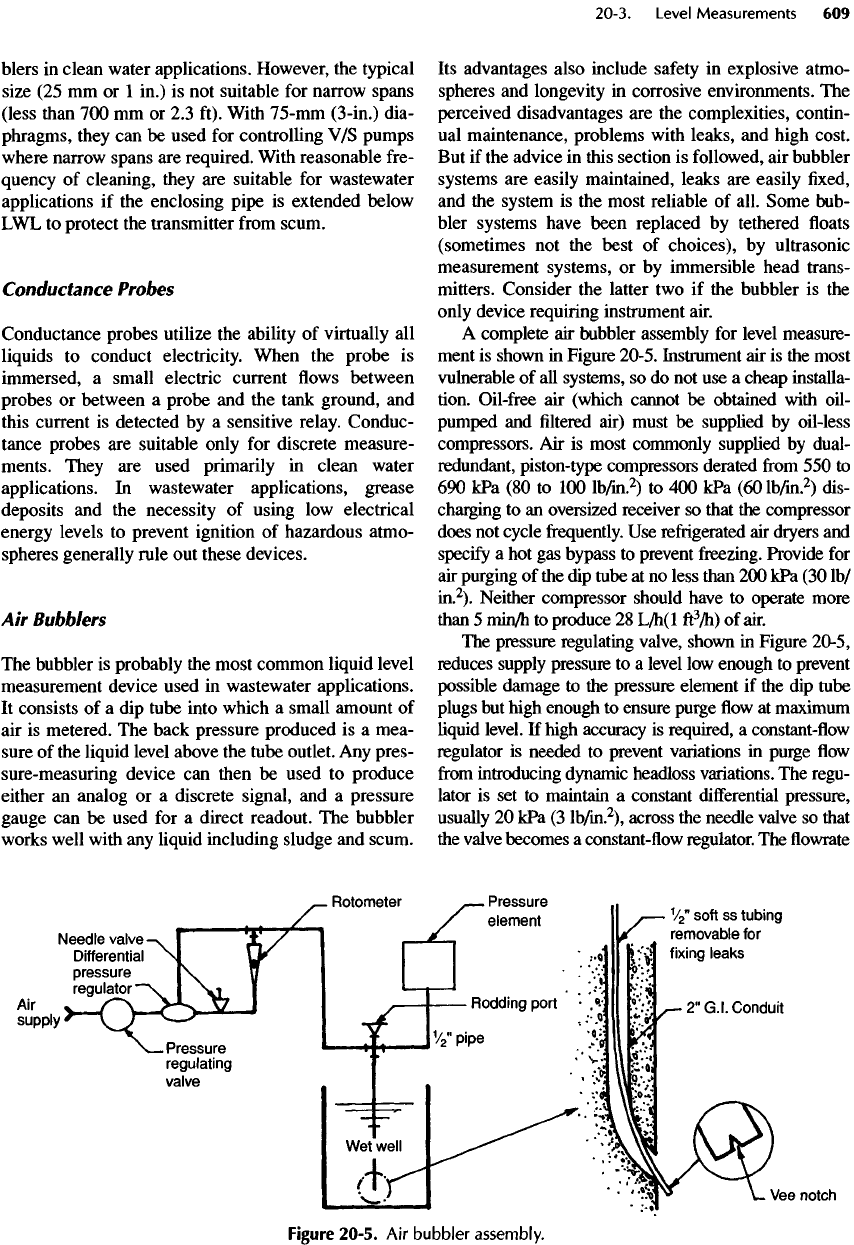
A
complete
air
bubbler assembly
for
level measure-
ment
is
shown
in
Figure 20-5. Instrument
air is the
most
vulnerable
of all
systems,
so do not use a
cheap installa-
tion. Oil-free
air
(which cannot
be
obtained with oil-
pumped
and filtered
air) must
be
supplied
by
oil-less
compressors.
Air is
most commonly supplied
by
dual-
redundant,
piston-type compressors derated
from 550 to
690
kPa
(80 to 100
lb/in.
2
)
to 400
kPa
(60
lb/in.
2
)
dis-
charging
to an
oversized receiver
so
that
the
compressor
does
not
cycle
frequently. Use
refrigerated
air
dryers
and
specify
a hot gas
bypass
to
prevent freezing. Provide
for
air
purging
of the dip
tube
at no
less than
200 kPa (30
Ib/
in.
2
).
Neither compressor should have
to
operate more
than
5
min/h
to
produce
28
L/h(l
ft
3
/h) of
air.
The
pressure regulating valve, shown
in
Figure 20-5,
reduces supply pressure
to a
level
low
enough
to
prevent
possible
damage
to the
pressure element
if the dip
tube
plugs
but
high enough
to
ensure purge
flow at
maximum
liquid
level.
If
high accuracy
is
required,
a
constant-flow
regulator
is
needed
to
prevent variations
in
purge
flow
from
introducing
dynamic headloss variations.
The
regu-
lator
is set to
maintain
a
constant
differential
pressure,
usually
20 kPa (3
lb/in.
2
),
across
the
needle valve
so
that
the
valve becomes
a
constant-flow
regulator.
The flowrate
Figure
20-5.
Air
bubbler
assembly.
is
measured
by the
rotameter.
Usually,
the
differential
pressure
regulator, needle valve,
and flow
indicator
are
furnished
as a
factory-assembled unit.
Ak flow is
typi-
cally
adjusted
to
about
0.025
m
3
/h
(1.0
ft
3
/h), but the
flowrates
are
sometimes
a
third
as
much.
Dip
tubes should always
be
installed
so
that they
can
be
easily rodded
out if
they become plugged.
The
bottom
of the dip
tube
is
notched
to
keep bubble size
as
small
as
possible
to
maintain
the
highest accuracy.
Some engineers (and owners) prefer straight
dip
tubes
(for
easy rodding) made
of
13-mm
(
l
/
2
-in.)
Schedule
40 PVC or
stainless-steel (ss) pipe attached
to the
wet-
well wall with pillow blocks. Others prefer
to
install
soft
ss
tubing
in
50-mm (2-in.) conduit
of
harder
ss or
galvanized
steel encased
in the
concrete.
The
conduit
must
be
bent
so
that
the dip
tube
can
enter
the
pool,
but
the
bends must have
a
long radius
to
make
it
easy
to
insert
the dip
tube. Rodding must
be
done with
a
flexible rod
(preferably
furnished
by the
contractor).
In
either installation, make
all
joints,
especially
the
rodding port, easily accessible
for
finding
and
fixing
leaks. Joints should never
be
encased
in
concrete.
Pressure instruments used with bubbler systems
should
be
installed adjacent
to the
bubble pipe (dip
tube)
to
keep tubing lengths
as
short
as
possible
because long tubing runs
(e.g.,
30 m or 100 ft) can add
significant
time delays
to the
measurement, increase
the
possibility
of
leaks that disable
a
bubbler system,
and,
in
closed-loop control systems, cause instability.
One
way to
eliminate these
problems
is to
mount
the
purge
panel
and
pressure instruments
on a
wall
or
hand
rail
adjacent
to the
bubble pipe
to
keep tubing
runs
to
less than about
3 m (10
ft).
High
accuracy
is not
usually
required
for
pump con-
trol—especially
if the
range
of wet
well levels
is 1 m
(3 ft) or
more
—
so the
high cost
can be
somewhat
reduced
by
simplifying
the
system.
The
differential
pressure regulator
is
often
omitted even though this
causes
the
purge
flow to
vary
with liquid level,
and
small
errors result
from
changes
in
system dynamic
pressure
losses
and
changes
in
bubble size.
If an
analog
signal
is
required,
a
bubbler with
an
electronic
change-
of-pressure transmitter
is
satisfactory. Providing
a
dif-
ferent
(or
even
an
additional) system
for
backup
is
good
practice,
so use a float
switch
for the
high-level alarm.
Diaphragm
Boxes
A
diaphragm
box
consists
of a
closed
box
with
an
elastomer diaphragm
forming
one
wall.
The
system
is
obsolete
and has
been supplanted
by
immersible
elec-
tronic pressure elements, which
may be
installed
in
the
same
fashion
and are
much more accurate.
Differential
Pressure Elements
Differential
pressure units
may be flange
mounted
to
a
tank
to
expose
the
pressure element directly
to the
fluid.This
approach
is
practical only when
(1)
freez-
ing
does
not
occur
or can be
prevented
and (2)
access
to the
side
of the
tank
is
readily available.
If the
tank
is not at
atmospheric pressure,
a
second connection
must
be
made above
the
maximum
fluid
level.
The
pressure exerted
on the
pressure element
is
then
a
direct indication
of the fluid
head above
the
connec-
tion point. This system, which
is
simple
and
very
accurate,
is the
favored
level measuring system
in
industrial applications,
but it
does
not
work
if the
spe-
cific
gravity
of the fluid in the
tank
is
unpredictable.
An
isolating valve
can be
placed between
the
pressure
unit
and the
tank
to
facilitate instrument maintenance
without emptying
the
tank,
but
this modification
entails
a
length
of
piping between
the
pressure ele-
ment
and the
tank that
is
subject
to
clogging
in
dirty
water applications.
Install
a
water connection
for
convenient
flushing
of
any
pipe
used between
the
vessel
and the
dia-
phragm. Flushing
can
done
be at
regular intervals
or a
continuous small
flow can be
used
to
isolate
the
pres-
sure cell
from
contaminated
fluid.
20-4. Pressure Measurements
Pressure
is a
basic measurement that
is
made
not
only
for
itself
but
also
for
converting many other measure-
ments into readable parameters.
For
example,
many
level
and flow
measurement systems produce
a
pres-
sure that
can
infer
a
value
for
another parameter.
Pres-
sure
is, in
fact,
almost always measured
as a
differential
pressure. Atmospheric pressure
is
nor-
mally
the
reference,
but
virtually
all
pressure-measur-
ing
elements
can be
arranged
for
connection
of an
independent reference pressure.
The
various types
of
pressure elements
are
summarized
in
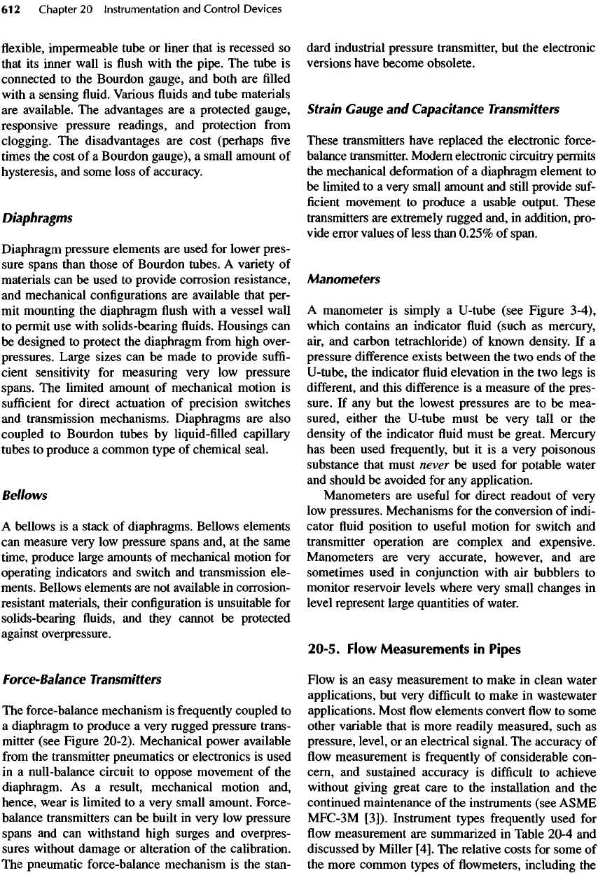
Table 20-3.
Pressure gauges should
be
installed
on
both
the
suction
and
discharge
spools
(short
pipe
section)
of
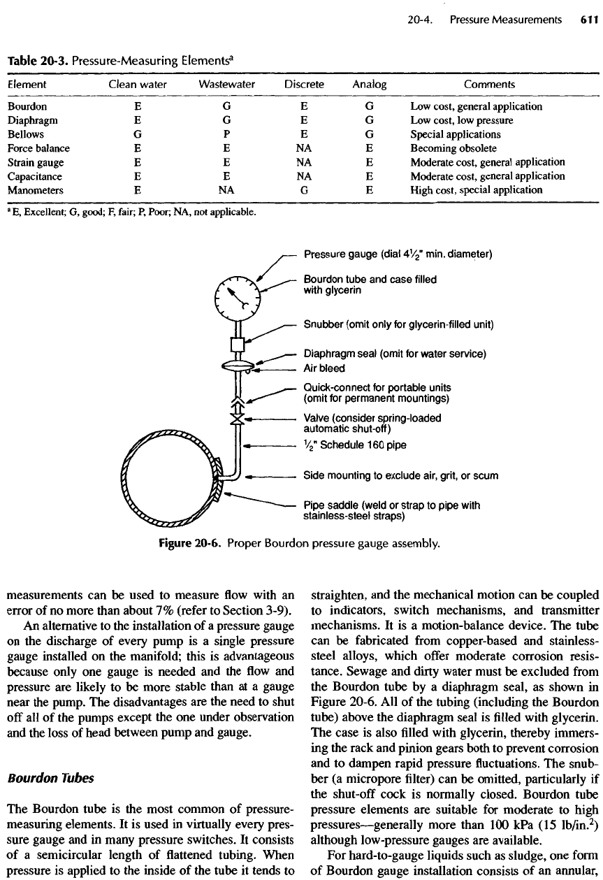
every pump (see Figure
20-6).
Instead
of fixed
gauges,
however, pressure taps with short,
12-mm
(
l
/
2
-in.)
pipes terminating
in
shut-off
cocks
and
quick-con-
nects allow more accurate portable gauges
to be
used.
Portable gauges
are
advantageous because only
two
are
required
and
they
can be
kept
in
calibrated condi-
tion. Suction
and
discharge pressures
are
valuable
checks
on the
condition
of the
station because they
can
be
used
to
diagnose such
troubles
as
blockages,
deposits
in the
pipe,
and
worn impellers.
In
conjunc-
tion with
the
manufacturer's pump curve, pressure
measurements
can be
used
to
measure
flow
with
an
error
of no
more than about
7%
(refer
to
Section 3-9).
An
alternative
to the
installation
of a
pressure gauge
on
the
discharge
of
every pump
is a
single pressure
gauge
installed
on the
manifold; this
is
advantageous
because only
one
gauge
is
needed
and the flow and
pressure
are
likely
to be
more stable than
at a
gauge
near
the
pump.
The
disadvantages
are the
need
to
shut
off
all of the
pumps except
the one
under observation
and
the
loss
of
head between pump
and
gauge.
Bourdon Tubes
The
Bourdon tube
is the
most common
of
pressure-
measuring elements.
It is
used
in
virtually every pres-
sure gauge
and in
many pressure
switches.
It
consists
of
a
semicircular length
of flattened
tubing. When
pressure
is
applied
to the
inside
of the
tube
it
tends
to
straighten,
and the
mechanical motion
can be
coupled
to
indicators, switch mechanisms,
and
transmitter
mechanisms.
It is a
motion-balance device.
The
tube
can be
fabricated
from
copper-based
and
stainless-
steel alloys, which
offer
moderate corrosion resis-
tance. Sewage
and
dirty water must
be
excluded
from
the
Bourdon tube
by a
diaphragm seal,
as
shown
in
Figure 20-6.
All of the
tubing (including
the
Bourdon
tube)
above
the
diaphragm seal
is filled
with glycerin.
The
case
is
also
filled
with glycerin, thereby immers-
ing
the
rack
and
pinion gears both
to
prevent corrosion
and
to
dampen rapid pressure
fluctuations. The
snub-
ber
(a
micropore
filter) can be
omitted, particularly
if
the
shut-off
cock
is
normally closed. Bourdon tube
pressure elements
are
suitable
for
moderate
to
high
pressures
—
generally
more than
100
kPa
(15
lb/in.
2
)
although low-pressure gauges
are
available.
For
hard-to-gauge liquids such
as
sludge,
one
form
of
Bourdon gauge installation consists
of an
annular,
Figure
20-6.
Proper
Bourdon
pressure
gauge
assembly.
Table
20-3.
Pressure-Measuring
Elements
3
Element
Clean
water Wastewater
Discrete
Analog
Comments
Bourdon
E
GEG
Low
cost,
general
application
Diaphragm
E
GEG
Low
cost,
low
pressure
Bellows
G
PEG
Special
applications
Force
balance
E E NA E
Becoming
obsolete
Strain
gauge
E E NA E
Moderate
cost,
general
application
Capacitance
E E NA E
Moderate
cost,
general
application
Manometers
E NA G E
High
cost,
special
application
a
E,
Excellent;
G,
good;
F,
fair;
P,
Poor;
NA, not
applicable.
flexible,
impermeable tube
or
liner that
is
recessed
so
that
its
inner wall
is flush
with
the
pipe.
The
tube
is
connected
to the
Bourdon gauge,
and
both
are
filled
with
a
sensing
fluid.
Various
fluids and
tube materials
are
available.
The
advantages
are a
protected
gauge,
responsive pressure readings,
and
protection
from
clogging.
The
disadvantages
are
cost (perhaps
five
times
the
cost
of a
Bourdon gauge),
a
small amount
of
hysteresis,
and
some loss
of
accuracy.
Diaphragms
Diaphragm pressure elements
are
used
for
lower pres-
sure
spans than those
of
Bourdon tubes.
A
variety
of
materials
can be
used
to
provide corrosion resistance,
and
mechanical
configurations
are
available that per-
mit
mounting
the
diaphragm
flush
with
a
vessel wall
to
permit
use
with
solids-bearing
fluids.
Housings
can
be
designed
to
protect
the
diaphragm
from
high over-
pressures. Large sizes
can be
made
to
provide
suffi-
cient sensitivity
for
measuring very
low
pressure
spans.
The
limited amount
of
mechanical motion
is
sufficient
for
direct actuation
of
precision switches
and
transmission mechanisms. Diaphragms
are
also
coupled
to
Bourdon tubes
by
liquid-filled
capillary
tubes
to
produce
a
common type
of
chemical
seal.
Bellows
A
bellows
is a
stack
of
diaphragms. Bellows elements
can
measure very
low
pressure spans and,
at the
same
time, produce large amounts
of
mechanical motion
for
operating indicators
and
switch
and
transmission ele-
ments. Bellows elements
are not
available
in
corrosion-
resistant
materials, their
configuration
is
unsuitable
for
solids-bearing
fluids, and
they cannot
be
protected
against
overpressure.
Force-Balance Transmitters
The
force-balance mechanism
is
frequently
coupled
to
a
diaphragm
to
produce
a
very rugged pressure trans-
mitter
(see Figure
20-2).
Mechanical power available
from
the
transmitter pneumatics
or
electronics
is
used
in
a
null-balance circuit
to
oppose
movement
of the
diaphragm.
As a
result, mechanical motion and,
hence, wear
is
limited
to a
very small amount. Force-
balance transmitters
can be
built
in
very
low
pressure
spans
and can
withstand high surges
and
overpres-
sures
without
damage
or
alteration
of the
calibration.
The
pneumatic force-balance mechanism
is the
stan-
dard industrial pressure transmitter,
but the
electronic
versions
have become
obsolete.
Strain Gauge
and
Capacitance Transmitters
These transmitters have replaced
the
electronic force-
balance transmitter. Modern
electronic
circuitry permits
the
mechanical deformation
of a
diaphragm element
to
be
limited
to a
very small amount
and
still provide suf-
ficient
movement
to
produce
a
usable output. These
transmitters
are
extremely rugged and,
in
addition, pro-
vide error values
of
less than 0.25%
of
span.
Manometers
A
manometer
is
simply
a
U-tube
(see Figure 3-4),
which
contains
an
indicator
fluid
(such
as
mercury,
air,
and
carbon
tetrachloride)
of
known density.
If a
pressure
difference
exists between
the two
ends
of the
U-tube,
the
indicator
fluid
elevation
in the two
legs
is
different,
and
this
difference
is a
measure
of the
pres-
sure.
If any but the
lowest pressures
are to be
mea-
sured, either
the
U-tube must
be
very tall
or the
density
of the
indicator
fluid
must
be
great. Mercury
has
been
used frequently,
but it is a
very poisonous
substance that must never
be
used
for
potable water
and
should
be
avoided
for any
application.
Manometers
are
useful
for
direct readout
of
very
low
pressures. Mechanisms
for the
conversion
of
indi-
cator
fluid
position
to
useful
motion
for
switch
and
transmitter
operation
are
complex
and
expensive.
Manometers
are
very accurate, however,
and are
sometimes used
in
conjunction with
air
bubblers
to
monitor reservoir levels where very small changes
in
level represent large quantities
of
water.
20-5. Flow
Measurements
in
Pipes
Flow
is an
easy measurement
to
make
in
clean water
applications,
but
very
difficult
to
make
in
wastewater
applications. Most
flow
elements convert
flow to
some
other variable that
is
more readily measured, such
as
pressure, level,
or an
electrical signal.
The
accuracy
of
flow
measurement
is
frequently
of
considerable con-
cern,
and
sustained accuracy
is
difficult
to
achieve
without
giving great care
to the
installation
and the
continued maintenance
of the
instruments (see ASME
MFC-3M
[3]).
Instrument types frequently used
for
flow
measurement
are
summarized
in
Table 20-4
and
discussed
by
Miller
[4].
The
relative costs
for
some
of
the
more common types
of flowmeters,
including
the
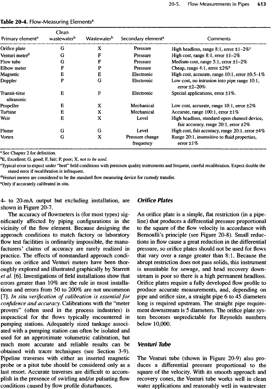
4- to
20-mA
output
but
excluding installation,
are
shown
in
Figure 20-7.
The
accuracy
of flowmeters is
(for most types)
sig-
nificantly
affected
by
piping configurations
in the
vicinity
of the flow
element. Because designing
the
approach conditions
to
match factory
or
laboratory
flow
test
facilities
is
ordinarily impossible,
the
manu-
facturers'
claims
of
accuracy
are
rarely realized
in
practice.
The
effects
of
nonstandard approach condi-
tions
on
orifice
and
Venturi meters have been thor-
oughly
explored
and
illustrated graphically
by
Starrett
et
al.
[6].
Investigations
of field
installations show that
errors greater than
10% are the
rule
in
most installa-
tions
and
errors
from
50 to
200%
are not
uncommon
[7].
In
situ
verification
of
calibration
is
essential
for
confidence
and
accuracy. Calibrations with
the
"meter
provers"
(often
used
in the
process industries)
is
impractical
for the flows
typically encountered
in
pumping
stations. Adequately sized tankage associ-
ated with
a
pumping station
can
often
be
isolated
and
used
for an
approximate volumetric calibration,
but
much
more accurate
and
reliable results
can be
obtained
with tracer techniques
(see
Section
3-9).
Pipeline traverses with either
an
inserted magnetic
probe
or a
pitot tube should
be
considered only
as a
last resort. Accurate traverses
are
difficult
to
accom-
plish
in the
presence
of
swirling and/or pulsating
flow
conditions caused
by flow
profile
disturbances.
Orifice
Plates
An
orifice
plate
is a
simple,
flat
restriction
(in a
pipe-
line) that produces
a
differential pressure proportional
to the
square
of the flow
velocity
in
accordance with
Bernoulli's principle
(see
Figure 20-8). Small reduc-
tions
in flow
cause
a
great reduction
in the
differential
pressure,
so
orifice
plates should
not be
used
for flows
that
vary over
a
range greater than
8:1.
Because
the
abrupt
restriction does
not
pass solids, this instrument
is
unsuitable
for
sewage,
and
head recovery down-
stream
is
poor
so
there
is a
high permanent headloss.
Orifice
plates require
a
fully
developed
flow
profile
to
produce accurate measurements,
and,
depending
on
pipe
and
orifice size,
a
straight pipe
6 to 45
diameters
long
is
required upstream.
The
straight pipe require-
ment
downstream
is 5
diameters.
The
orifice plate sys-
tem
becomes unpredictable
for
Reynolds numbers
below
10,000.
Venturi Tube
The
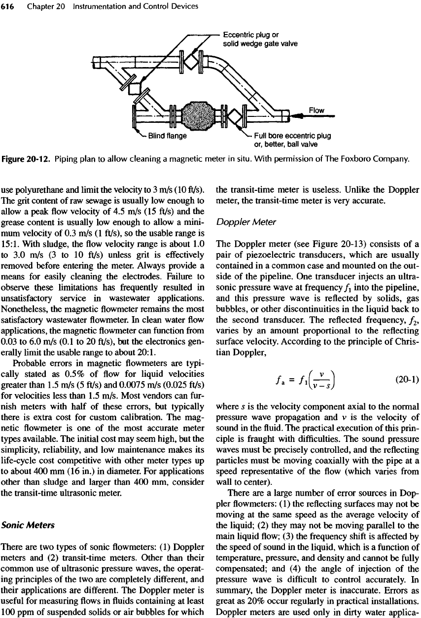
Venturi tube (shown
in
Figure
20-9)
also
pro-
duces
a
differential
pressure proportional
to the
square
of the
velocity. With
its
smooth approach
and
recovery cones,
the
Venturi tube works well
in
clean
water
applications
and
reasonably well
in
wastewater
Table
20-4. Flow-Measuring
Elements
3
Clean
Primary
element
3
wastewater
b
Wastewater
b
Secondary
element
3
Comments
Orifice
plate
G X
Pressure
High
headless,
range
8:1,
error
±1-2%
C
Venturi
meter*
1
G F
Pressure
High
cost,
range
8:
!,error
±1-2%
Flow
tube
G F
Pressure
Medium
cost,
range
5:1,
error
±1-2%
Elbow
meter
F P
Pressure
Cheap,
range
4:
!,error
±2%
e
Magnetic
E E
Electronic
High
cost,
accurate,
range
10:
!,error
±0.5-1%
Doppler
P G
Electronic
Low
cost,
no
intrusion
into
pipe
range
10:1,
error
±2-20%
Transit-time
E F
Electronic
Special
applications,
error
±1%.
ultrasonic
Propeller
E X
Mechanical
Low
cost,
accurate,
range
10:
!,error
±2%
Turbine
E X
Mechanical
Accurate,
range
100:1,
error
±1%
Weir
E X
Level
High
headloss,
standard
open
channel
device,
fair
accuracy,
range
20:1,
error
±2%
Flume
G G
Level
High
cost,
fair
accuracy,
range
20:
!,error
±4%
Vortex
G X
Pressure
change
Range
20:1,
insensitive
to fluid
properties,
frequency
error
±
1
%
a
See
Chapter
2 for
definition.
5
E,
Excellent;
G,
good;
F,
fair;
P,
poor;
X, not to be
used.
c
Typical
error
to
expect
under
"best"
field
conditions with premium quality instruments
and
frequent, careful
recalibration.
Expect
double
the
stated error
if
recalibration
is
infrequent.
d
Venturi
meters
are
considered
to be the
standard
flow
measuring device
for
custody transfer.
6
OnIy
if
accurately calibrated
in
situ.
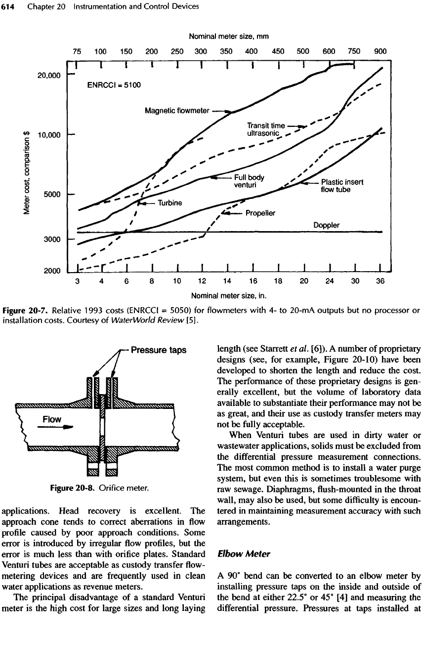
Figure
20-8.
Orifice
meter.
applications. Head recovery
is
excellent.
The
approach cone tends
to
correct aberrations
in flow
profile
caused
by
poor approach conditions. Some
error
is
introduced
by
irregular
flow
profiles,
but the
error
is
much less than
with
orifice
plates. Standard
Venturi
tubes
are
acceptable
as
custody
transfer
flow-
metering devices
and are
frequently
used
in
clean
water applications
as
revenue meters.
The
principal disadvantage
of a
standard
Venturi
meter
is the
high cost
for
large sizes
and
long laying
length (see
Starrett
et
al.
[6]).
A
number
of
proprietary
designs (see,
for
example, Figure 20-10) have been
developed
to
shorten
the
length
and
reduce
the
cost.
The
performance
of
these proprietary designs
is
gen-
erally excellent,
but the
volume
of
laboratory data
available
to
substantiate their performance
may not be
as
great,
and
their
use as
custody
transfer
meters
may
not be
fully
acceptable.
When
Venturi
tubes
are
used
in
dirty water
or
wastewater
applications,
solids
must
be
excluded
from
the
differential
pressure measurement connections.
The
most common method
is to
install
a
water purge
system,
but
even this
is
sometimes troublesome with
raw
sewage. Diaphragms,
flush-mounted in the
throat
wall,
may
also
be
used,
but
some
difficulty
is
encoun-
tered
in
maintaining measurement accuracy
with
such
arrangements.
Elbow Meter
A
90°
bend
can be
converted
to an
elbow meter
by
installing pressure taps
on the
inside
and
outside
of
the
bend
at
either 22.5°
or 45° [4] and
measuring
the
differential
pressure. Pressures
at
taps installed
at
Figure 20-7. Relative
1993
costs (ENRCCI
=
5050)
for
flowmeters
with
4- to
20-mA
outputs
but no
processor
or
installation
costs. Courtesy
of
WaterWorld Review
[5].
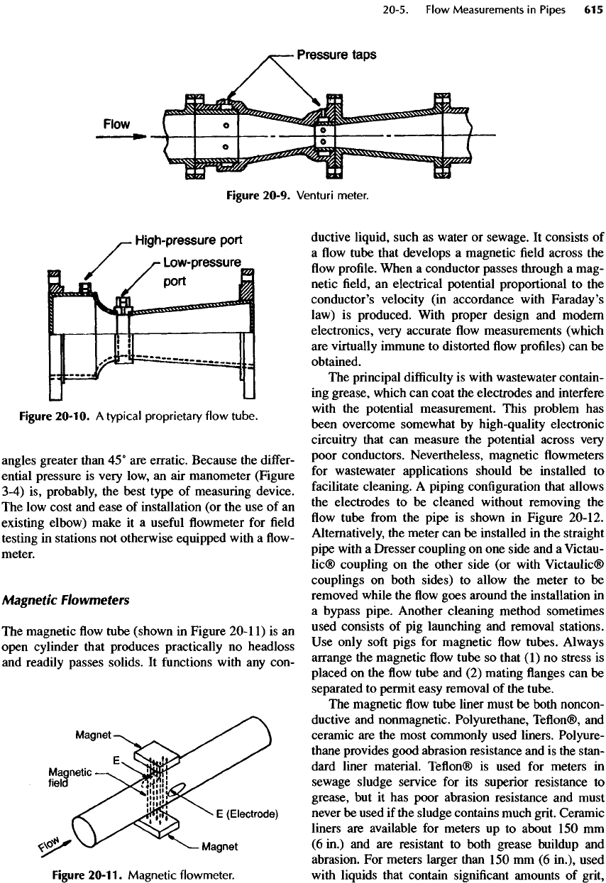
Figure
20-10.
A
typical
proprietary
flow
tube.
angles greater than
45°
are
erratic. Because
the
differ-
ential pressure
is
very
low,
an air
manometer (Figure
3-4)
is,
probably,
the
best type
of
measuring device.
The low
cost
and
ease
of
installation
(or the use of an
existing elbow) make
it a
useful
flowmeter for field
testing
in
stations
not
otherwise equipped with
a flow-
meter.
Magnetic
Flowmeters
The
magnetic
flow
tube (shown
in
Figure
20-1
1)
is an
open cylinder that produces practically
no
headloss
and
readily passes solids.
It
functions
with
any
con-
Figure
20-11.
Magnetic
flowmeter.
ductive
liquid, such
as
water
or
sewage.
It
consists
of
a
flow
tube that develops
a
magnetic
field
across
the
flow
profile.
When
a
conductor passes through
a
mag-
netic
field, an
electrical
potential
proportional
to the
conductor's velocity
(in
accordance with Faraday's
law)
is
produced. With proper design
and
modern
electronics,
very accurate
flow
measurements (which
are
virtually immune
to
distorted
flow
profiles)
can be
obtained.
The
principal
difficulty
is
with wastewater contain-
ing
grease, which
can
coat
the
electrodes
and
interfere
with
the
potential measurement. This problem
has
been overcome somewhat
by
high-quality electronic
circuitry that
can
measure
the
potential
across very
poor conductors. Nevertheless, magnetic
flowmeters
for
wastewater applications should
be
installed
to
facilitate
cleaning.
A
piping configuration that allows
the
electrodes
to be
cleaned
without removing
the
flow
tube
from
the
pipe
is
shown
in
Figure 20-12.
Alternatively,
the
meter
can be
installed
in the
straight
pipe with
a
Dresser coupling
on one
side
and a
Victau-
lic®
coupling
on the
other side
(or
with
Victaulic®
couplings
on
both sides)
to
allow
the
meter
to be
removed while
the flow
goes around
the
installation
in
a
bypass pipe. Another cleaning method sometimes
used consists
of pig
launching
and
removal
stations.
Use
only
soft
pigs
for
magnetic
flow
tubes. Always
arrange
the
magnetic
flow
tube
so
that
(1) no
stress
is
placed
on the flow
tube
and (2)
mating
flanges can be
separated
to
permit easy removal
of the
tube.
The
magnetic
flow
tube liner must
be
both noncon-
ductive
and
nonmagnetic.
Polyurethane,
Teflon®,
and
ceramic
are the
most commonly used
liners.
Polyure-
thane
provides good abrasion resistance
and is the
stan-
dard
liner material.
Teflon®
is
used
for
meters
in
sewage sludge service
for its
superior resistance
to
grease,
but it has
poor abrasion resistance
and
must
never
be
used
if the
sludge contains much grit. Ceramic
liners
are
available
for
meters
up to
about
150 mm
(6
in.)
and are
resistant
to
both
grease
buildup
and
abrasion.
For
meters larger than
150
mm (6
in.),
used
with
liquids that contain
significant
amounts
of
grit,
Figure
20-9. Venturi meter.
use
polyurethane
and
limit
the
velocity
to 3
m/s
(10
ft/s).
The
grit content
of raw
sewage
is
usually
low
enough
to
allow
a
peak
flow
velocity
of 4.5
m/s
(15
ft/s)
and the
grease content
is
usually
low
enough
to
allow
a
mini-
mum
velocity
of 0.3
m/s
(1
ft/s),
so the
usable range
is
15:1.
With
sludge,
the flow
velocity range
is
about
1.0
to 3.0
m/s
(3 to 10
ft/s)
unless grit
is
effectively
removed
before entering
the
meter. Always provide
a
means
for
easily cleaning
the
electrodes. Failure
to
observe these limitations
has
frequently
resulted
in
unsatisfactory
service
in
wastewater applications.
Nonetheless,
the
magnetic
flowmeter
remains
the
most
satisfactory
wastewater
flowmeter. In
clean water
flow
applications,
the
magnetic
flowmeter can
function
from
0.03
to 6.0
m/s
(0.1
to 20
ft/s),
but the
electronics
gen-
erally
limit
the
usable range
to
about
20:1.
Probable errors
in
magnetic
flowmeters are
typi-
cally
stated
as
0.5%
of flow for
liquid velocities
greater than
1.5
m/s (5
ft/s)
and
0.0075
m/s
(0.025
ft/s)
for
velocities less than
1.5
m/s. Most vendors
can
fur-
nish
meters with half
of
these errors,
but
typically
there
is
extra cost
for
custom calibration.
The
mag-
netic
flowmeter is one of the
most accurate meter
types
available.
The
initial cost
may
seem high,
but the
simplicity,
reliability,
and low
maintenance makes
its
life-cycle
cost competitive with other meter types
up
to
about
400 mm (16
in.)
in
diameter.
For
applications
other than sludge
and
larger than
400 mm,
consider
the
transit-time ultrasonic meter.
Sonic
Meters
There
are two
types
of
sonic
flowmeters: (1)
Doppler
meters
and (2)
transit-time meters. Other than their
common
use of
ultrasonic pressure waves,
the
operat-
ing
principles
of the two are
completely
different,
and
their applications
are
different.
The
Doppler meter
is
useful
for
measuring
flows in fluids
containing
at
least
100
ppm
of
suspended
solids
or air
bubbles
for
which
the
transit-time meter
is
useless.
Unlike
the
Doppler
meter,
the
transit-time meter
is
very accurate.
Doppler
Meter
The
Doppler meter (see Figure
20-13)
consists
of a
pair
of
piezoelectric transducers, which
are
usually
contained
in a
common case
and
mounted
on the
out-
side
of the
pipeline.
One
transducer injects
an
ultra-
sonic pressure wave
at
frequency/!
into
the
pipeline,
and
this pressure wave
is
reflected
by
solids,
gas
bubbles,
or
other discontinuities
in the
liquid back
to
the
second transducer.
The
reflected frequency,
/
2
,
varies
by an
amount proportional
to the
reflecting
surface
velocity. According
to the
principle
of
Chris-
tian Doppler,
/a
=
/,(;£)
(20-1)
where
s is the
velocity component axial
to the
normal
pressure wave propagation
and v is the
velocity
of
sound
in the fluid. The
practical
execution
of
this prin-
ciple
is
fraught
with
difficulties.
The
sound pressure
waves
must
be
precisely controlled,
and the
reflecting
particles must
be
moving coaxially with
the
pipe
at a
speed representative
of the flow
(which varies
from
wall
to
center).
There
are a
large number
of
error sources
in
Dop-
pler
flowmeters:
(1)
the
reflecting
surfaces
may not be
moving
at the
same speed
as the
average velocity
of
the
liquid;
(2)
they
may not be
moving parallel
to the
main
liquid
flow; (3) the
frequency
shift
is
affected
by
the
speed
of
sound
in the
liquid, which
is a
function
of
temperature, pressure,
and
density
and
cannot
be
fully
compensated;
and (4) the
angle
of
injection
of the
pressure wave
is
difficult
to
control accurately.
In
summary,
the
Doppler meter
is
inaccurate. Errors
as
great
as 20%
occur regularly
in
practical installations.
Doppler meters
are
used only
in
dirty water applica-
Figure
20-12.
Piping
plan
to
allow
cleaning
a
magnetic
meter
in
situ.
With
permission
of The
Foxboro
Company.
