Pumping Station Desing - Second Edition by Robert L. Sanks, George Tchobahoglous, Garr M. Jones
Подождите немного. Документ загружается.

Detailed examples
of
calculations using this devel-
opment
are
presented
by the
U.S.
EPA
[2].
Data
for
Different
Sludge
Types
There
is now a
growing data base
for
different
types
of
sludge
for
estimating sludge
coefficients
[16-18].
These data indicate that
an
increase
in the
content
of
unstabilized
(undigested) biological solids
in a
sludge
causes
an
increase
in the
coefficient
of
rigidity
and
hence
an
increase
in the
dynamic headloss
in
sludge
pipelines.
The
headlosses
may be
considerably higher
than
those indicated
for the
worst case
in
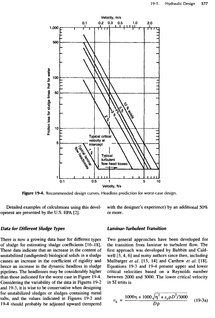
Figure 19-4.
Considering
the
variability
of the
data
in
Figures 19-2
and
19-3,
it is
wise
to be
conservative when designing
for
unstabilized sludges
or
sludges containing metal
salts,
and the
values indicated
in
Figures 19-2
and
19-4 should probably
be
adjusted
upward (tempered
with
the
designer's
experience)
by an
additional
50%
or
more.
Laminar-Turbulent Transition
Two
general approaches have been developed
for
the
transition
from
laminar
to
turbulent
flow. The
first
approach
was
developed
by
Babbitt
and
CaId-
well
[3, 4, 6] and
many authors since then, including
Mulbarger
et
al.
[13,
14] and
Carthew
et
al.
[18].
Equations 19-3
and
19-4 present upper
and
lower
critical velocities based
on a
Reynolds number
between
2000
and
3000.
The
lower critical velocity
in
SI
units
is
lOOOri
+
1000
JnT+
s
v
p£>
2
/3000
Dp
(19
"
3a)
Figure
19-4.
Recommended
design
curves.
Headloss
prediction
for
worst-case
design.
and
the
upper critical velocity
is
_
1500Ti
+
1500,^VSyPD
2
MSOO
Vuc
Dp
where
both critical velocities
are in
meters
per
second.
In
U.S. Customary Units
the
lower critical velocity
is
1000r|
+
lOOoTn
5
+
J
y
Y^
2
/3000
v
k
-
Dy
<
19
-
3b
>
and
the
upper critical velocity
is
1500Ti
+
1500,/r?
+
5
yY
£D
2
/4500
V
uc
Dy
{*
)
where both critical velocities
are in
feet
per
second.
Equations
19-2, 19-3,
and
19-4 have been used
by
several authors
and
work
fairly
well
for
most sludges.
Hanks
and
Dadia [19] criticized using only
the
Reynolds number
and
suggested
the
addition
of the
Hedstrom number
for a
more
rigorous
determination
of
the
transition turbulent
flow of a
Bingham plastic.
Although
somewhat complex,
the
approach requires
only
the
yield stress,
coefficient
of rigidity,
density,
and
pipe diameter.
The
Hedstrom number
is
defined
in
SI
units
as
H
=
D
V
<
19
-
5a
>
T!
where
H is the
dimensionless Hedstrom number
and
other terms
are as
defined
above.
In
U.S. Customary
Units,
H
=
°
S
f
cY
(19-5b)
T!
Figure 19-5.
Recommended
design
curves.
Headloss
prediction
for
routine
operation.
where
H is the
dimensionless Hedstrom number
and
other terms
are as
defined
above.
A
special Reynolds
number
is
also calculated
(see
Figure
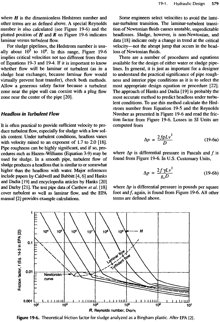
19-6)
and the
plotted position
of H and R on
Figure
19-6
indicates
laminar versus turbulent
flow.
For
sludge pipelines,
the
Hedstrom number
is
usu-
ally
about
10
5
to
10
6
.
In
this range, Figure
19-6
implies critical velocities
not too
different
from
those
of
Equations
19-3
and
19-4.
If it is
important
to
know
whether
flow
will
be
laminar
or
turbulent
(as in a
sludge heat exchanger,
because
laminar
flow
would
virtually
prevent heat transfer), check both methods.
Allow
a
generous
safety
factor because
a
turbulent
zone near
the
pipe wall
can
coexist with
a
plug
flow
zone near
the
center
of the
pipe
[2O].
Headloss
in
Turbulent Flow
It
is
often
practical
to
provide
sufficient
velocity
to
pro-
duce
turbulent
flow,
especially
for
sludge with
a low
sol-
ids
content. Under turbulent conditions, headloss vanes
with
velocity raised
to an
exponent
of 1.7 to 2.0
[18].
Pipe roughness
can be
highly
significant,
and if so,
pro-
cedures such
as
Hazen-Williams
(Equation
3-9)
may be
used
for
sludge.
In a
smooth pipe, turbulent
flow of
sludge
produces
a
headloss that
is
similar
to or
somewhat
higher than
the
headloss with water.
Major
references
include papers
by
Caldwell
and
Babbitt
[4,
6]
and
Hanks
and
Dadia
[19]
and
encyclopedia articles
by
Hanks
[20]
and
Darby
[21].
The
test pipe data
of
Carthew
et
al
[18]
cover turbulent
as
well
as
laminar
flow, and the EPA
manual
[2]
provides example calculations.
Some engineers
select
velocities
to
avoid
the
lami-
nar-turbulent
transition.
The
laminar-turbulent transi-
tion
of
Newtonian
fluids
causes unstable, unpredictable
headlosses. Sludge, however,
is
non-Newtonian,
and
data
[18]
indicate only
a
change
in
trend
at the
critical
velocity
—
not
the
abrupt jump that occurs
in the
head-
loss
of
Newtonian
fluids.
There
are a
number
of
procedures
and
equations
available
for the
design
of
either water
or
sludge pipe-
lines.
In
general,
it is
just
as
important
for a
designer
to
understand
the
practical
significance
of
pipe
rough-
ness
and
interior pipe conditions
as it is to
select
the
most appropriate design equation
or
procedure
[22].
The
approach
of
Hanks
and
Dadia
[19]
is
probably
the
most accurate method
to
predict headloss under turbu-
lent conditions.
To use
this method calculate
the
Hed-
strom number
from
Equation
19-5
and the
Reynolds
Number
as
presented
in
Figure
19-6
and
read
the
fric-
tion factor
from
Figure
19-6.
Losses
in SI
Units
are
computed
from
Ap
=
2
^
Lv2
(19-6a)
where
Ap is
differential
pressure
in
Pascals
and / is
found
from
Figure
19-6.
In
U.S.
Customary Units,
Ap
=
2
^v
2
(19
.
6b)
where
Ap is
differential
pressure
in
pounds
per
square
foot
and/,
again,
is
found
from
Figure
19-6.
All
other
terms
are
defined
above.
Figure
19-6.
Theoretical
friction
factor
for
sludge analyzed
as a
Bingham plastic.
After
EPA
[2].
As
with water under turbulent
conditions,
the fric-
tion
loss
in
sludge
flow is
approximately proportional
to
velocity squared
but
modified
by a
multiplier
found
by
using Figure
19-4
or
19-5.
Mulbarger
[13,
14]
suggested
a 50%
allowance
for
worst-case design
for
headloss under turbulent
flow
conditions.
The 50%
allowance
is
equivalent
to
using
a
Hazen-Williams
C of
about
1
10
instead
of
140.
The
difference
between sludge
and
water increases with
an
increase
of
solids under both laminar
and
turbulent
flow as
shown
by
recent experiments
[18].
If the two
Bingham
parameters
(s
y
and
J])
can be
determined
with
accuracy,
the
procedure
of
Hanks
and
Dadia [19]
may
be a
more exact method.
It is
certainly wise
to
allow
for an
increase
in
pipe roughness
due to
moder-
ate
deposits
of
grit
and
grease.
The
above
safety
fac-
tor, however,
may not
suffice
under some conditions,
especially
at
higher solids concentrations. Wherever
more accuracy
is
needed
(as in all but
short pipelines),
the
graph
of
Figure 19-6 should
be
used.
Thixotropy
Sludges
sometimes exhibit characteristics
of
thixot-
ropy;
at
other times they display characteristics simi-
lar to
those
of a
Bingham plastic.
In
thixotropic
behavior,
flow
resistance depends
on the
time
at
rest,
so
high pressure
is
needed
to
start
the fluid
moving
after
it has
been
at
rest. Because some studies have
shown
that sludge
is
markedly thixotropic,
it is
good
practice
to
assume that thixotropy
may
occur and,
hence, raise
the
friction loss
in
suction piping. Suction
piping should therefore
be as
short
as
practical.
After
passing through
a
pump, thixotropic
effects
are
unlikely
to be
important, except when restarting
a
pipeline that
has
been shut down while
full
of
concen-
trated
sludge.
Simplified
Headloss Calculations
Most
of the
above information
has
been available
for
many
years
but has not
been widely used.
A
recent
advance
has
been
the
compilation
of
Figures
19-4
and
19-5.
The use of
these
figures is
demonstrated
in
Example
19-1,
in
which sludge
is
considered
to be a
Bingham
plastic
with
values
of
s
y
and
Tj,
as
shown
in
Figures 19-2
and
19-3.
The
factors obtained
from
Fig-
ures
19-4
and
19-5
are
compared
to
losses
for
water
using
the
Hazen-Williams equation with
a C
value
of
140. Choose velocity
and
percent solids, compute
the
friction
headloss
for
water,
and
multiply
the
headloss
by
the
factors
from
Figure
19-4
(worst case)
or
Figure
19-5
(routine
design).
These
figures
cover laminar
and
turbulent
flow
conditions, both
of
which
are
widely
used.
At
lower velocities, sludge
friction
decreases
only slowly
as
velocity drops. With water, however,
friction
drops sharply
as
velocity drops. Hence,
the
sludge/water headloss ratio increases
as
velocity
decreases. Above
a
critical velocity, sludge
flows
more like water
and
friction varies
as
velocity
to an
exponent
of
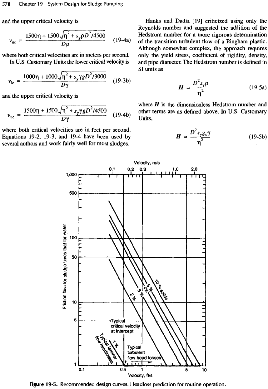
about 1.85. Figure 19-4 includes
a
factor
of
1.5
in
this region. Headloss also varies with solids
content, especially
at the
lower velocities.
Consider
the
following when using Figures 19-4
and
19-5:
•
Figures 19-4
and
19-5, supplemented with data
published since 1980,
are far
more accurate than
popular references published before 1970. These
figures
were proposed
by
Mulbarger [14]
to
repre-
sent
the
general case(s) based
on
further
examina-
tion
of
data derived
in his
earlier work
[13].
•
Figures 19-4
and
79-5 must
be
used
correctly.
The
water
headloss
is
computed
as a
basis
for the
sludge
headloss. Most engineers
are
comfortable with
the
approach
of (1)
calculating headlosses
for
water
for
a
selected pipe roughness
and
then
(2)
multiplying
the
headloss
by a
selected sludge
factor.
The
factors
in
Figures 19-4
and
19-5
are
based
on an H-W C
factor
of 140 for
water.
Do not use a
different
C
fac-
tor
even
if you
would
do so for
water. Minor
losses
should never
be
computed
as
equivalent
pipe
lengths
but
should
be
computed separately. Minor
loss
coefficients
may be
taken
as
roughly
the
same
for
sludge
as for
water.
•
Some sludges
may
exceed
the
"design
worst-case"
curves
of
Figure 19-4.
For
undigested activated
sludge,
the
design worst-case should
be
raised
by a
factor
of 1.5
until more data
are
available.
A
similar
factor
may
apply
to
primary
and
secondary sludges
that contain aluminum
or
iron salts.
• The
charts should
be
used with great caution
for
pump
suction piping
in the
calculation
of
available
net
positive suction head
(NPSH
A
).
Even
if
NPSH
A
appears
to be
adequate, long suction pipelines rep-
resent poor practice
and
should
not be
allowed
because
of
possible thixotropy.
•
Lower velocities
and
larger pipe
may or may not
reduce total
friction
headlosses. Calculate headlosses
for
at
least
two
pipe sizes
and
evaluate capital, oper-
ating,
and
maintenance (pipe cleaning) costs before
deciding
the
pipe size (see Example 19-1).
•
Figures 19-4
and
19-5
are
inadequate
for
highly
accurate results. Accuracy
is
especially
important
when
the
pumped distance
is
large
or
when
signifi-
cant
variations
in
sludge
are
expected.
A
strongly
suggested
guideline
is to
conduct
a
specific
testing
program
whenever
(1) the
pipeline
is
more than
1.6
km
(1 mi)
long,
(2) the
sludge
is
expected
to be at
or
over
7%
solids,
(3) a fluctuation in fluid
charac-
teristics
of the
sludge
is
likely
to
occur,
or (4)
calcu-
lations
based
on
Figure
19-4
indicate
a
friction
head
greater than
15
m
(50
ft).
• Do not
assume that resistances obtained
by
testing
will
never
be
exceeded. Design
the
facility
to
allow
for
diluting
the
sludge
to
ensure
an
adequate instal-
lation.
19-2.
Types
of
Pumps
Depending
on the
application, sludge pumps
can be
centrifugal,
vortex, combined screw-centrifugal,
air
lift,
or
positive displacement pumps such
as
plunger
(or
piston), progressive cavity, diaphragm, rotary lobe,
and
high-pressure
piston. These pumps
are
described
in
Chapter
11
and
compared
in
Table
25-10.
In
general,
centrifugal
pumps
are
most suitable
for
pumping large
volumes
of
sludge
at low (2 or 3%)
concentrations,
whereas
higher concentrations
and
intermittent pump-
ing
warrant
the use of a
positive-displacement pump.
Centrifugal
Pumps
The
preferred choice
of
centrifugal pumps
for
sludge
applications
is the
nonclog pump because
of the
need
for
larger passages through vanes
to
prevent obstruc-
tions.
In
general, pumps
for
moving sludge
fall
in the
low
end of the
mixed-flow
range
of
specific
speeds.
Sludge pumps must
be
sturdier with larger, more
reli-
able bearings,
shafts,
seals,
and
other internal compo-
nents. Reliability
is
preferred over pumping
efficiency.
One of the
major
problems
in
selecting
a
centrifu-
gal
pump
for
sludge
is the
difficulty
in
obtaining
the
proper size
for
both
flow and
head conditions.
(An
example
of the
range
of
design considerations
is
pre-
sented
in
Example 19-1.)
Due to the
wide range
of
expected
flow
conditions, variable-speed (V/S) con-
trol
is
usually used.
The
discharge valve should
not
be
throttled
in an
attempt
to
control
flow
because
throttling
promotes increased valve wear, plugging
of
the
pipeline,
and
wasted energy. Velocity criteria
in
the
sludge piping system
are
often
compromised
when
the
pump capacity
is
reduced
and the
head
is
raised
by
throttling
a
discharge valve.
The
impeller
can be
specified
to
include
one or
more vanes
and to be
enclosed,
semi-enclosed,
or
open.
Efficiencies
tend
to be
higher
for
enclosed
impellers
and
lower
for
open impellers. Closed impel-
lers
are
best suited
for
large return activated sludge
pumps
or raw
waste pumps with suction
and
discharge
pipes
of 200 mm (8
in.)
or
larger. Open
or
recessed
impellers
are
better
for
smaller-volume pumping
applications involving stringy material
and for
suction
and
discharge piping sizes
of 100 to 150 mm (4 to 6
in.).
Centrifugal pumps
are not
recommended
for
very
small
volumes
of
sludge with suction
and
discharge
piping
less
than
100 mm (4
in.).
Note that many
designers object
to
pipe smaller than
150 mm (6
in.)
and
refuse
to use
pipe smaller than
100 mm (4
in.)
for
sludge
in any
circumstances.
Vortex
Pumps
The
impeller
of a
vortex pump (also
called
a
"recessed
impeller pump") develops
a
vortex
in the
incoming
fluid so
that most
of the
solids never touch
the
impel-
ler.
The
openings through
the
pump
are
large because
the
impeller
is
almost entirely
out of the
liquid
flow
path,
so the
plugging
often
encountered with nonclog
pumps
is
eliminated. (Despite
the
name, nonclog
pumps
often
clog.) Hence,
the
size
of
solids
is
limited
mostly
by the
size
of the
suction
and
discharge noz-
zles. Vortex pumps have
the
advantages
of
less main-
tenance, greater reliability,
and
greater ease
of
parts
replacement.
But the
sizing
of
vortex pumps
is
critical
because they have very
flat
system head
curves
—
a
major
complication when pumping thicker sludges
(because
of the
highly variable pressure drop). Inter-
nal
fluid
recirculation
is a
concern,
the
efficiency
is
very
low
(only
45% or
less),
and in
some types
the
impellers cannot
be
trimmed.
In
summary,
the
vortex
pump
is a
desirable selection when
the
sludge pump-
ing
system requirements
are
such that reliability
is
paramount
in the
pumping
of
sludge with
a low
(say,
4%
or
less) concentration
of
solids.
Vortex pumps
can
pump
up to
about
6%
solids,
but a
variable-speed
drive
and a
reliable
flowmeter are
required
to
allow
process control
at
higher solids contents. Rugged
mechanical construction also becomes critical
as
vary-
ing
process conditions
may
require
the
pump
to
oper-
ate
away
from
its
best
efficiency
point (bep).
A
positive means
of
moving sludge through
the
suction
piping into
the
pump must
be
available
if
pumping
is
to
be
reliable.
Horizontal mounting
is
recommended, because
vertical installations
can
result
in
noise and/or cavita-
tion.
Restrictions
are
often
built into
the
discharge pas-
sages
of the
pump
to
steepen
the flat
system head
curves,
so do not
fail
to
specify
the
size
of
sphere that
must
pass entirely through
the
suction, discharge,
and
internal passages
of the
pump.
Combined
Screw-Centrifugal Pumps
Recognizing
the
inherent problems
in
pumping
sludge, pump manufacturers have periodically
offered
innovative
designs.
One
type (such
as the
Chicago
Pump
Scru-Peller®),
used
for
half
a
century, com-
bines
a
two-flight
screw conveyor with
an
open-type,
two-blade centrifugal nonclog impeller.
It was
designed
and
applied particularly
for
primary sludge
pumping.
The
sharp
stellite
edges
of the
screw con-
veyor
and
impeller
and the
stellite shear bars
in the
screw
housing
cut or
shred stringy materials.
The
advantages
of the
Scru-Peller® pump
are its
ability
to (1)
cope with stringy materials,
(2)
produce
a
steady discharge,
(3)
develop heads
up to 50 m
(160
ft)
at 160
m
3
/h
(700
gal/min),
and (4)
minimize clog-
ging
effects
and
associated downtime
and
mainte-
nance.
The
disadvantages
are
primarily higher
first
cost
and
operating costs
as
compared with costs
for a
centrifugal
nonclog pump
but
less
as
compared with
costs
for a
vortex pump.
The
pump
is
best
applied
for
intermittent
pumping instead
of
continuous duty.
A
pump that
has
become almost standard
for
sludge pumping
and has
often
been used
to
replace
an
inefficient
vortex pump
is the
combined screw-
centrifugal
impeller pump (such
as the
WEMCO
Hidrostal®). This type
of
pump
has
been
applied
to
sludges
for
about
16
years
in the
United States.
The
design
was
developed
to
pump live
fish
without dam-
age
for
canneries.
The
impeller
has two
sections
(screw
and
centrifugal) that combine
the
clog-free
features
of a
vortex pump with
the
gentle action
of a
screw
pump
at the
higher
efficiencies
of a
centrifugal
pump.
The
large open channels
in the fluid
path pro-
vide pumping without
the
abrupt changes
in
direc-
tion that capture stringy materials.
It is
claimed that
the
corkscrew action
of the
screw section helps
to
start thicker sludges moving.
The
advantages
of
this
pump
include
(1)
higher
(up to
80%)
efficiencies,
(2)
nonclog operation,
(3)
gentle
fluid
action without
high
turbulence,
(4) a
steep head-capacity curve,
(5)
low
NPSH requirements,
and (6) a
nonoverloading
power curve.
The
disadvantage
is
that
for a
given
flow
rate,
it is
larger
and
more expensive than
a
cen-
trifugal
pump.
Both
of
these pump types
may be
useful
when
the
combination
of
steady discharge with clog-free opera-
tion
is
desired.
The
pumping
of
primary sludge
and of
sludges
with stringy
and fibrous
materials
are
said
to
be
good applications
for
both
of
these pumps.
Air
Lift
Pumps
Air
lift
pumps
are
sometimes
used
for the
thin sludges
produced
at
oxidation ditches
or
other small extended
aeration activated sludge plants. Because
the
control
of
pumping rate
is
limited
for a
single pump, they
are
often
installed
in
multiples.
Air
lift
pumps
are
used
for
activated sludge return where
the
lift
is
low
—
typically
less than
2 m (6 ft)
—
and
the
pipeline
is
short
[23].
The
pump
itself
is
almost indestructible and, except
for
the
splashing
and the
daily need
for
cleaning,
requires virtually
no
maintenance.
The air
blowers,
however,
do
require maintenance.
The
pump
has
sev-
eral disadvantages:
(1) it is
difficult
to
regulate
flow
(so
process
control
is
also
difficult);
(2) the
pumpage
changes erratically with small variations
in the air
delivered;
and (3) the
efficiency
is low
(typically
less
than
30%).
The
best
way to
regulate discharge
is to
maintain
the
maximum
air
pressure entering
the
pump
and
close
(or
open)
the air
exhaust ports
at the
bottom
of
the
pump column. Rushing connections
are
recom-
mended.
Plunger Pumps
The
plunger
(or
"piston")
pump
has
long been
a
work-
horse
and is one of the
most commonly used types
for
pumping
sludge.
The
piston
is
driven
by an
exposed
drive
crank whose eccentricity
is
adjustable and, thus,
provides
a
stroke length that
can be
varied
to
suit
the
desired output.
The
discharge
from
a
plunger pump
is
therefore
a
series
of
interrupted sinusoidal pulses,
so
the
"pulsed"
flow (at the
peak
of the
sine curve)
is
greater than
the
average
flow. The
pulsing
effect
is
reduced with multiple piston (duplex
or
triplex)
pumps
and/or with
air
chambers. Design calculations
must
be
based
on the
peak
of the
pulsing
flow.
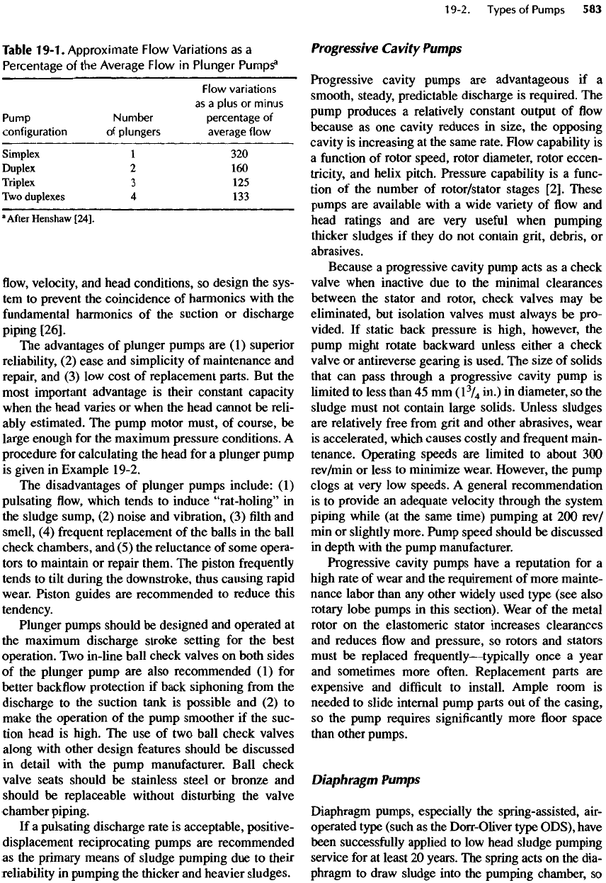
The
approximate
flow
variations
as a
percentage
of
the
average
flow are
shown
in
Table
19-1.
Because
the
tabular
values
are
based
on the
assumption
of a rigid
machine
and an
incompressible
fluid, the
observed
effects
may be
somewhat less. Nevertheless, discuss
this
aspect
of
pump performance with
the
pump man-
ufacturer.
Air
chambers should
be
specified
on the
suction side when
the
suction head
is
more than
4.6 m
(15 ft), and
they should always
be
furnished
on the
discharge
side.
Air
chambers,
or
pulsation dampeners,
induce
a
more
uniform
flow. The
volume
of an air
chamber
or
dampener
for
simplex pumps should
be
six
to
eight times
the
displacement
of one
plunger
per
stroke
(V
8
);
for
duplex
and
triplex pumps,
the
volume
should
be
three
to
four
times
V
8
[25].
The
kinematics
of
reciprocating pumps produce periodic variations
in
Table
19-1.
Approximate
Flow
Variations
as a
Percentage
of the
Average
Flow
in
Plunger
Pumps
3
Flow
variations
as a
plus
or
minus
Pump
Number
percentage
of
configuration
of
plungers
average
flow
Simplex
1 320
Duplex
2 160
Triplex
3 125
Two
duplexes
4 133
a
After
Henshaw
[24].
flow,
velocity,
and
head conditions,
so
design
the
sys-
tem
to
prevent
the
coincidence
of
harmonics with
the
fundamental
harmonics
of the
suction
or
discharge
piping
[26].
The
advantages
of
plunger pumps
are (1)
superior
reliability,
(2)
ease
and
simplicity
of
maintenance
and
repair,
and (3) low
cost
of
replacement parts.
But the
most
important advantage
is
their constant capacity
when
the
head varies
or
when
the
head cannot
be
reli-
ably
estimated.
The
pump motor must,
of
course,
be
large enough
for the
maximum
pressure conditions.
A
procedure
for
calculating
the
head
for a
plunger pump
is
given
in
Example 19-2.
The
disadvantages
of
plunger pumps include:
(1)
pulsating
flow,
which tends
to
induce
"rat-holing"
in
the
sludge sump,
(2)
noise
and
vibration,
(3) filth and
smell,
(4)
frequent
replacement
of the
balls
in the
ball
check chambers,
and (5) the
reluctance
of
some opera-
tors
to
maintain
or
repair them.
The
piston frequently
tends
to
tilt during
the
downstroke, thus causing rapid
wear.
Piston guides
are
recommended
to
reduce this
tendency.
Plunger pumps should
be
designed
and
operated
at
the
maximum discharge stroke setting
for the
best
operation.
Two
in-line ball check valves
on
both sides
of
the
plunger pump
are
also recommended
(1) for
better
backflow
protection
if
back siphoning
from
the
discharge
to the
suction tank
is
possible
and (2) to
make
the
operation
of the
pump smoother
if the
suc-
tion head
is
high.
The use of two
ball check valves
along
with other design features should
be
discussed
in
detail with
the
pump manufacturer. Ball check
valve
seats should
be
stainless steel
or
bronze
and
should
be
replaceable without disturbing
the
valve
chamber piping.
If
a
pulsating discharge rate
is
acceptable, positive-
displacement
reciprocating
pumps
are
recommended
as the
primary means
of
sludge pumping
due to
their
reliability
in
pumping
the
thicker
and
heavier sludges.
Progressive Cavity Pumps
Progressive cavity pumps
are
advantageous
if a
smooth,
steady, predictable discharge
is
required.
The
pump
produces
a
relatively constant output
of flow
because
as one
cavity reduces
in
size,
the
opposing
cavity
is
increasing
at the
same rate. Flow capability
is
a
function
of
rotor speed, rotor diameter, rotor eccen-
tricity,
and
helix pitch. Pressure capability
is a
func-
tion
of the
number
of
rotor/stator stages
[2].
These
pumps
are
available with
a
wide variety
of flow and
head ratings
and are
very
useful
when pumping
thicker sludges
if
they
do not
contain grit, debris,
or
abrasives.
Because
a
progressive cavity pump acts
as a
check
valve
when inactive
due to the
minimal clearances
between
the
stator
and
rotor, check valves
may be
eliminated,
but
isolation valves must always
be
pro-
vided.
If
static back pressure
is
high, however,
the
pump
might rotate backward unless either
a
check
valve
or
antireverse gearing
is
used.
The
size
of
solids
that
can
pass through
a
progressive cavity pump
is
limited
to
less than
45 mm
(l
3
/
4
in.)
in
diameter,
so the
sludge
must
not
contain large
solids.
Unless sludges
are
relatively
free
from
grit
and
other abrasives, wear
is
accelerated, which causes costly
and
frequent
main-
tenance. Operating
speeds
are
limited
to
about
300
rev/min
or
less
to
minimize wear. However,
the
pump
clogs
at
very
low
speeds.
A
general recommendation
is to
provide
an
adequate velocity through
the
system
piping while
(at the
same time) pumping
at 200
rev/
min
or
slightly more. Pump speed should
be
discussed
in
depth with
the
pump manufacturer.
Progressive cavity pumps have
a
reputation
for a
high
rate
of
wear
and the
requirement
of
more mainte-
nance labor than
any
other widely used type (see also
rotary
lobe pumps
in
this section). Wear
of the
metal
rotor
on the
elastomeric
stator increases clearances
and
reduces
flow and
pressure,
so
rotors
and
stators
must
be
replaced
frequently
—
typically
once
a
year
and
sometimes more
often.
Replacement parts
are
expensive
and
difficult
to
install. Ample room
is
needed
to
slide internal pump parts
out of the
casing,
so the
pump requires
significantly
more
floor
space
than
other pumps.
Diaphragm Pumps
Diaphragm
pumps, especially
the
spring-assisted, air-
operated type (such
as the
Dorr-Oliver type ODS), have
been
successfully applied
to low
head sludge pumping
service
for at
least
20
years.
The
spring acts
on the
dia-
phragm
to
draw sludge into
the
pumping chamber,
so
the
pump
is
capable
of a
modest suction
lift
although
high
suction
lift
cannot
be
sustained reliably
[27].
Com-
pressed
air
forces
the
sludge
out of the
pumping cham-
ber. Check valves
on the
inlet
and
discharge
connections prevent
backflow.
Stroke adjustment
and
timer control
of the air
supply solenoid permits
a
wide
range
of
pumping rates. Nonassist
and
pneumatic-assist
types
are
available.
The
pump
can be
furnished with
ball-type check valves
in
either singles
or
pairs with
quick
opening covers (recommended). Capacities range
up
to 34
m
3
/h
(150
gal/min)
as
water (and
60% or
more
of
such values
as
sludge)
at 350
kPa
(50
lb/in.
2
)
gauge.
Compressed
air
requirements
are
significant, however,
and
the air
exhaust
can be
quite noisy. Diaphragm
pumps
have
a
good reputation, problems
are
few,
and
they
are
suitable
for
small treatment plants.
The
disadvantages include:
(1)
pulsating
flow, (2)
vibration,
(3)
requirement
for
compressed
air and
con-
sequent
inefficiency,
and (4)
high
cost
per
unit
of flow.
The
type
with
a
single valve
for
suction
and
discharge
is not
suitable
for
stringy materials,
but
valves
in
tan-
dem
pairs
can be
obtained
or the
pump
can be
pre-
ceded
by a
grinder.
Membranes typically last about
two
years
if the air
supply
and the
solenoid
air
valve
are
properly
adjusted.
Cracks
in the
membrane
can be
readily
detected,
so the
membrane
can be
replaced
before
it
ruptures
entirely.
A
ruptured membrane allows
the air
lines
to fill
with sludge
to the
muffler,
but the
muffler
liner
quickly
clogs
so
that
little
sludge
can
spill.
Cleaning
the air
lines
is a
chore; membranes should
be
replaced well before cracks develop.
The O&M
man-
ual
should contain
a
warning about
the
danger
of
flooding the
station with sludge
if a
muffler
and
liner
are not in
place. Better protection
is
afforded
by
mounting
the
muffler
high enough
to
prevent
any
pos-
sible spill.
Another diaphragm pump options consists
of a
low-pressure pump using dual
free
or
unbalanced dia-
phragms
driven
by an
eccentric
shaft.
The
features
of
the
pump include
a
mechanical drive, self-priming
characteristics, ability
to
operate
at
speeds reduced
to
a
"snore"
condition,
the
elimination
of
check valves
and
moving
seals,
and an
unusually
low
number
of
moving parts.
The
pump
is
valveless
and
glandless
and
is
able
to
operate
dry for a
short time without
damage.
It has
been available since
the
mid-1980s
and
has
been successfully applied
in
over
2000
sludge
pumping applications.
The
pump
can
reportedly han-
dle up to
8.5% solids
[28].
This type
of
diaphragm
pump
is
limited
to a TDH of 100
feet
(or
less
for the
largest
model).
Maximum
solids-handling
capacity
is
1 in. The
pump tends
to
retain
its
performance over
its
operating
life
because disc
and
seal wear
is
low.
Be
cautious, however,
in
specifying this pump, because,
when
overpressurized,
it can
break internally without
warning.
Applications should
be
reviewed with
the
manufacturer
in
detail.
Rotary Lobe Pumps
The
rotary lobe pump
has
been applied
to
wastewater
sludges only since 1970
but
with promising results.
Its
advantages
are (1)
positive displacement with lit-
tle
agitation
or
shear,
(2)
high
efficiency,
(3)
self-
priming,
(4)
compactness,
(5)
good
accessibility
for
maintenance,
and (6)
sizes
up to
0.12
m
3
/s
(2000
gal/
min).
The
disadvantages
are (1) the
lack
of an
exten-
sive operating history
and (2)
close
clearances that
are
subject
to
wear
and
abrasion (which makes slud-
ges
containing much grit, abrasives,
debris,
and
rags
unsuitable).
Difficulties
have been experienced with
a
number
of
rotary lobe pumps (installed between 1980
and
1988)
in
which rapid wear
of
lining materials
and
sometimes catastrophic loss
of
liners
have occurred,
according
to a
survey conducted
in
late 1988
[29].
Some operators reported rapid wear
of end
plates
and
a
resulting loss
of
volumetric capacity.
The
causes
were
sorption
of
water
by the
liners
and
failure
of the
adhesive.
The
problems have since been corrected
[3O].
Rotary lobe pumps
are so
compact that
it
might
be
difficult
to
replace
an
unsatisfactory unit with
another type because
of
space limitations.
High-Pressure Piston Pumps
Belt conveyors
and
screw conveyors
are
usually used
to
move dewatered sludge
to
truck loading points
or
incinerators.
An
alternative recently developed
is the
use of
specially designed piston pumps
to
force dewa-
tered sludge through
pipes.
The
basic
pump design
is
derived
from
concrete
pumps.
A
high-pressure piston pump typically
has two
pumping
cylinders
of
small diameter
and
long stroke.
Each cylinder
is
driven
by the
pressure
of
hydraulic
oil in an
adjacent drive cylinder. Hydraulic
oil is
also
used
to
power-operate
the
valves, because ordinary
check valves
are not
satisfactory
in
plastic
fluids
with
high yield stress.
At the
pump intake,
a
short screw
conveyor
may be
used
to
force sludge
into
the
pump.
The
installation
is
mechanically complex
and
requires
considerable
floor
space,
but
other conveying systems
have
the
same drawbacks.
Very
high pressure drops occur although data
are
sparse.
In one
unpublished test
of a
sludge containing
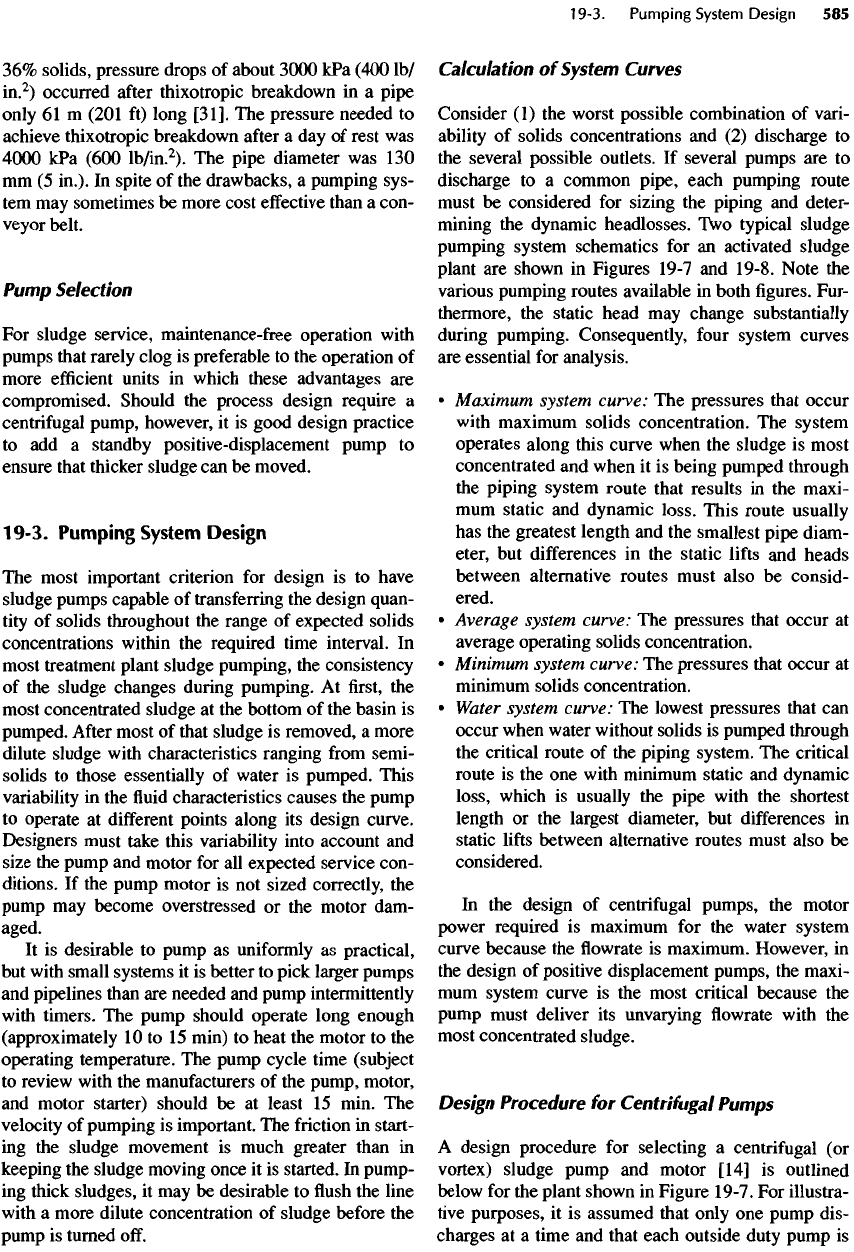
36%
solids, pressure drops
of
about
3000
kPa
(400
Ib/
in.
2
)
occurred
after
thixotropic breakdown
in a
pipe
only
61 m
(201
ft)
long
[31].
The
pressure needed
to
achieve thixotropic breakdown
after
a day of
rest
was
4000
kPa
(600
lb/in.
2
).
The
pipe diameter
was 130
mm
(5
in.).
In
spite
of the
drawbacks,
a
pumping sys-
tem
may
sometimes
be
more cost
effective
than
a
con-
veyor
belt.
Pump
Selection
For
sludge service, maintenance-free operation with
pumps
that rarely clog
is
preferable
to the
operation
of
more
efficient
units
in
which these advantages
are
compromised. Should
the
process design require
a
centrifugal
pump, however,
it is
good design practice
to add a
standby positive-displacement pump
to
ensure that thicker sludge
can be
moved.
19-3. Pumping
System
Design
The
most important criterion
for
design
is to
have
sludge
pumps capable
of
transferring
the
design quan-
tity
of
solids throughout
the
range
of
expected solids
concentrations within
the
required time interval.
In
most
treatment plant sludge pumping,
the
consistency
of
the
sludge changes during pumping.
At first, the
most
concentrated sludge
at the
bottom
of the
basin
is
pumped.
After
most
of
that sludge
is
removed,
a
more
dilute
sludge with characteristics ranging
from
semi-
solids
to
those essentially
of
water
is
pumped. This
variability
in the fluid
characteristics causes
the
pump
to
operate
at
different
points along
its
design curve.
Designers
must
take this variability into account
and
size
the
pump
and
motor
for all
expected service con-
ditions.
If the
pump motor
is not
sized correctly,
the
pump
may
become overstressed
or the
motor dam-
aged.
It is
desirable
to
pump
as
uniformly
as
practical,
but
with small systems
it is
better
to
pick larger pumps
and
pipelines than
are
needed
and
pump intermittently
with
timers.
The
pump should operate long enough
(approximately
10 to 15
min)
to
heat
the
motor
to the
operating temperature.
The
pump cycle time (subject
to
review with
the
manufacturers
of the
pump, motor,
and
motor starter) should
be at
least
15
min.
The
velocity
of
pumping
is
important.
The
friction
in
start-
ing
the
sludge movement
is
much greater than
in
keeping
the
sludge moving once
it is
started.
In
pump-
ing
thick sludges,
it may be
desirable
to flush the
line
with
a
more dilute concentration
of
sludge before
the
pump
is
turned
off.
Calculation
of
System Curves
Consider
(1)
the
worst possible combination
of
vari-
ability
of
solids concentrations
and (2)
discharge
to
the
several
possible
outlets.
If
several pumps
are to
discharge
to a
common pipe, each pumping route
must
be
considered
for
sizing
the
piping
and
deter-
mining
the
dynamic
headlosses.
Two
typical sludge
pumping
system schematics
for an
activated sludge
plant
are
shown
in
Figures 19-7
and
19-8. Note
the
various pumping routes available
in
both
figures.
Fur-
thermore,
the
static head
may
change substantially
during
pumping. Consequently,
four
system curves
are
essential
for
analysis.
•
Maximum system curve:
The
pressures that occur
with
maximum solids concentration.
The
system
operates along this curve when
the
sludge
is
most
concentrated
and
when
it is
being pumped through
the
piping system route that results
in the
maxi-
mum
static
and
dynamic
loss.
This route usually
has
the
greatest length
and the
smallest pipe diam-
eter,
but
differences
in the
static
lifts
and
heads
between alternative routes must also
be
consid-
ered.
•
Average system curve:
The
pressures that occur
at
average operating solids concentration.
•
Minimum system curve:
The
pressures that occur
at
minimum
solids
concentration.
•
Water
system curve:
The
lowest pressures that
can
occur when water without solids
is
pumped through
the
critical route
of the
piping system.
The
critical
route
is the one
with minimum static
and
dynamic
loss, which
is
usually
the
pipe with
the
shortest
length
or the
largest diameter,
but
differences
in
static
lifts
between alternative routes must also
be
considered.
In
the
design
of
centrifugal pumps,
the
motor
power required
is
maximum
for the
water system
curve
because
the flowrate is
maximum. However,
in
the
design
of
positive displacement pumps,
the
maxi-
mum
system curve
is the
most critical because
the
pump
must deliver
its
unvarying
flowrate
with
the
most concentrated sludge.
Design Procedure
for
Centrifugal
Pumps
A
design procedure
for
selecting
a
centrifugal
(or
vortex) sludge pump
and
motor [14]
is
outlined
below
for the
plant shown
in
Figure
19-7.
For
illustra-
tive purposes,
it is
assumed that only
one
pump dis-
charges
at a
time
and
that each outside
duty
pump
is
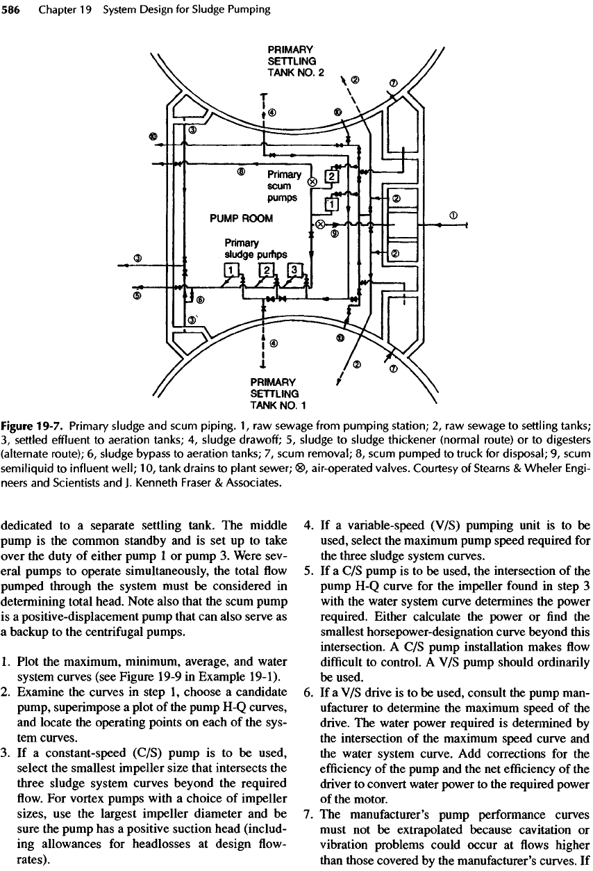
dedicated
to a
separate settling tank.
The
middle
pump
is the
common standby
and is set up to
take
over
the
duty
of
either pump
1 or
pump
3.
Were sev-
eral pumps
to
operate simultaneously,
the
total
flow
pumped through
the
system must
be
considered
in
determining total head. Note also that
the
scum pump
is
a
positive-displacement pump that
can
also serve
as
a
backup
to the
centrifugal pumps.
1.
Plot
the
maximum, minimum, average,
and
water
system
curves (see Figure 19-9
in
Example
19-1).
2.
Examine
the
curves
in
step
1,
choose
a
candidate
pump,
superimpose
a
plot
of the
pump
H-Q
curves,
and
locate
the
operating points
on
each
of the
sys-
tem
curves.
3. If a
constant-speed (C/S) pump
is to be
used,
select
the
smallest impeller size that intersects
the
three sludge system curves beyond
the
required
flow. For
vortex pumps with
a
choice
of
impeller
sizes,
use the
largest impeller diameter
and be
sure
the
pump
has a
positive suction head (includ-
ing
allowances
for
headlosses
at
design
flow-
rates).
4. If a
variable-speed (V/S) pumping unit
is to be
used,
select
the
maximum pump speed required
for
the
three sludge system curves.
5. If a C/S
pump
is to be
used,
the
intersection
of the
pump
H-Q
curve
for the
impeller
found
in
step
3
with
the
water system curve determines
the
power
required. Either calculate
the
power
or find the
smallest horsepower-designation curve beyond this
intersection.
A C/S
pump installation makes
flow
difficult
to
control.
A V/S
pump should ordinarily
be
used.
6. If a V/S
drive
is to be
used, consult
the
pump man-
ufacturer
to
determine
the
maximum speed
of the
drive.
The
water power required
is
determined
by
the
intersection
of the
maximum
speed
curve
and
the
water system curve.
Add
corrections
for the
efficiency
of the
pump
and the net
efficiency
of the
driver
to
convert water power
to the
required power
of
the
motor.
7. The
manufacturer's pump performance curves
must
not be
extrapolated because
cavitation
or
vibration problems could occur
at flows
higher
than those covered
by the
manufacturer's curves.
If
Figure
19-7.
Primary
sludge
and
scum
piping.
1,
raw
sewage
from
pumping
station;
2, raw
sewage
to
settling
tanks;
3,
settled
effluent
to
aeration
tanks;
4,
sludge
drawoff;
5,
sludge
to
sludge
thickener
(normal
route)
or to
digesters
(alternate
route);
6,
sludge
bypass
to
aeration
tanks;
7,
scum
removal;
8,
scum
pumped
to
truck
for
disposal;
9,
scum
semiliquid
to
influent
well;
10,
tank
drains
to
plant
sewer;
<8>,
air-operated
valves.
Courtesy
of
Stearns
&
Wheler
Engi-
neers
and
Scientists
and J.
Kenneth
Fraser
&
Associates.
