Pump Handbook by Igor J. Karassik, Joseph P. Messina, Paul Cooper, Charles C. Heald - 3rd edition
Подождите немного. Документ загружается.

2.3.1 CENTRIFUGAL PUMPS: GENERAL PERFORMANCE CHARACTERISTICS 2.355
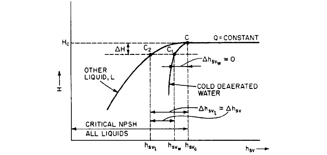
FIGURE 28 Cavitation tests with different liquids at constant speed and constant flow rate (Reference 34)
tain liquid hydrocarbons may be operated safely with less NPSH than would normally
be required for cold water. This may lower the cost of an installation appreciably, partic-
ularly in the case of refinery pumps. A theory for this has been given by Stepanoff and
others.
14,30–33
Figure 28 shows the results of cavitation tests on two liquids for constant
capacity and constant pump speed. No head loss due to cavitation is present at point C
or at h
sv
h
svc
. With cold deaerated water, lowering h
sv
, slightly below h
svc
produces lim-
ited cavitation and a decrease in pump head H to point C
1
, but h
svw
usually is negligi-
ble. With hot water (T 100°F 37.8°C) or with many liquid hydrocarbons, a much
larger decrease in h
sv
will be required to produce the same drop in head H that was
shown by the cold water test. The NPSH reduction, or NPSH adjustment, is H
sv
h
svl.
In practice, H has been limited to h 0.03H, for which there is a negligible sacrifice
in performance. The pumps usually are made of stainless steel or other cavitation-resis-
tant materials, and the lower NPSH results in lower collapse pressure of the vapor bub-
bles, reducing the damage potential.
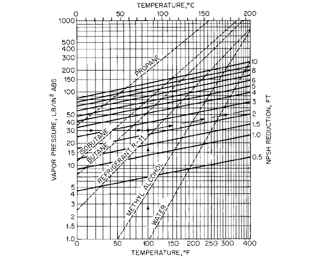
Chart for NPSH Reductions A composite chart of NPSH reductions for deaerated hot
water and certain gas-free liquid hydrocarbons is shown in Figure 29. The curves of
vapor pressure versus temperature and the curves of constant NPSH reduction were
based on laboratory tests with the liquids shown and should be used subject to the fol-
lowing limitations:
1. No NPSH reduction should exceed 50% of the NPSH required by the pump for cold
water or 10 ft (3.0 m), whichever is smaller.
2. NPSH may have to be increased above the normal cold-water value to avoid unsatis-
factory operation when (a) entrained air or other noncondensable gas is present in the
liquid or (b) dissolved air or other noncondensable gas is present in the liquid and the
absolute suction pressure is low enough to permit release of the gas from solution.
3. The vapor pressure of hydrocarbon mixtures vary significantly with temperature and
so should be determined at pumping temperature (see Reference 27).
4. If the suction system may be susceptible to transient changes in absolute pressure or
temperature, a suitable margin of safety in NPSH should be provided. This is partic-
ularly important with hot water and may exceed the reduction that would otherwise
apply with steady-state conditions.
5. Although experience has indicated the reliability of Figure 29 for hot water and the
liquid hydrocarbons shown, its use with other liquids is not recommended unless it is
clearly understood that the results must be accepted on an experimental basis.
2.356 CHAPTER TWO
FIGURE 29 NPSH reductions for pumps handling liquid hydrocarbons and hot water. This chart has been
constructed from test data obtained by using the liquids shown. For applicability to other liquids, refer to the text
(ft 0.3048 = m; lb/in
2
6.895 = kPa). (Hydraulic Institute ANSI/HI 2000 Edition Pump Standards, Reference 27)
*Sometimes it is possible to lower the pump, and this should be considered before other alterations are made.
USE OF FIGURE 29
Given a fluid having a vapor pressure of 30 lb/in
2
(210 kPa) abs at 100°F
(37.8°C). Follow the arrows on the key shown on the chart and obtain an NPSH reduc-
tion of about 2.3 ft (0.70 m). Since this does not correspond to one of the liquids for which
vapor pressure curves are shown on the chart, the use of this NPSH reduction should be
considered a tentative value only. Given a pump requiring 16-ft (4.9-m) cold-water NPSH
at the operating capacity, the pump is to handle propane at 55°F (12.8°C). Figure 29 shows
the vapor pressure to be about 105 lb/in
2
(733 kPa) abs and the NPSH reduction to be
about 9.5 ft (2.9 m). Since this exceeds 8 ft (2.44 m), which is half the cold-water NPSH,
the recommended NPSH for the pump handling propane is half the cold-water NPSH, or
8 ft (2.44 m). If the temperature of the propane in the previous example is reduced to 14°F
(10°C), Figure 29 shows the vapor pressure to be 50 lb/in
5
(349 kpa) abs and the NPSH
reduction to be about 5.7 ft (1.74 m), which is less than half the coldwater NPSH. The
NPSH required for pumping propane at 14°F (10°C) is then 16 5.7 10.3 10 ft
(4.87 1.74 3.13 3 m).
Reduction of Cavitation Damage After the pump has been built and installed*, there
is little that can be done to reduce cavitation damage. As previously mentioned, sharp-
ening the leading edges of the blades by filing may be beneficial. Stepanoff
12
has suggested
cutting back part of the blades in the impeller eye together with sharpening the tips, for
low-specific-speed pumps, as a means of reducing the inlet velocity c
1
and thus lowering
s. Although a small amount of prerotation or prewhirl in the direction of impeller rota-

2.3.1 CENTRIFUGAL PUMPS: GENERAL PERFORMANCE CHARACTERISTICS 2.357
tion may be desirable
34
, excessive amounts should be avoided. This may require straight-
ening vanes ahead of the impeller and rearranging the suction piping to avoid changes in
direction or other obstructions.The cavitation damage to the impeller shown in Figure 20
was believed to have been at least partly due to bad flow conditions produced by two 90°
elbows in the suction piping. The planes of the elbows were at 90° to each other, and this
arrangement should be avoided.
Straightening vanes in the impeller inlet may increase the NPSH requirement at all
flow rates.Three or four radial ribs equally spaced around the inlet and extending inward
about one-quarter of the inlet diameter are effective against excessive prerotation and
may require less NPSH than full-length vanes. This is very important with axial-flow
pumps, which are apt to have unfavorable cavitation characteristics at partial flow rates.
Operation near the best efficiency point usually minimizes cavitation.
The admission of a small amount of air into the pump suction tends to reduce cavita-
tion noise.
7
This rarely is done, however, because it is difficult to inject the right amount of
air under varying head and flow rate conditions and frequently there are objections to
mixing air with the liquid pumped.
If a new impeller is required because of cavitation, the design should take into account
the most recent advances described in the literature. Gongwer
35
has suggested (1) the use
of ample fillets where the vanes join the shrouds, (2) sharpened leading edges of vanes, (3)
reduction of b, in the immediate vicinity of the shrouds, and (4) raking the leading edges
of the vanes forward out of the eye. Increasing the number of vanes for propeller pumps
lowers s for a given submergence. A change in the impeller material may be very benefi-
cial, as described below.
Resistance of Materials to Cavitation Damage Table 8 shows the relative resistance
of several metals to cavitation pitting produced by magnetostriction vibration. It will be
seen that cast iron, the most commonly used material for impellers, has relatively little pit-
ting resistance relative to bronze and stainless steel, which are readily cast and finished.
Damage due to cavitation erosion is commonly assessed in terms of the depth of pene-
tration. The life of an impeller is generally considered to be the time required for cavita-
tion erosion to reach a depth of 75% of the blade thickness at any point
36
. The life of any
material in years can be expressed as the product of the mean depth of penetration rate
TABLE 8 Cavitation erosion resistance of metals
Alloy Magnetostriction weight loss after 2 h, mg
Rolled stellite
a
0.6
Welded aluminum bronze 3.2
Cast aluminum bronze 5.8
Welded stainless steel (2 layers, 17 Cr-7 Ni) 6.0
Hot rolled stainless steel (26 Cr-13 Ni) 8.0
Tempered rolled stainless steel (12 Cr) 9.0
Cast stainless steel (18 Cr-8 Ni) 13.0
Cast stainless steel (12 Cr) 20.0
Cast manganese bronze 80.0
Welded mild steel 97.0
Plate steel 98.0
Cast steel 105.0
Aluminum 124.0
Brass 156.0
Cast iron 224.0
a
Despite the high resistance of this material to cavitation damage, it is not suitable for ordinary
use because of its comparatively high cost and the difficulty encountered in machining and grinding.
Source: Reference 69.
2.358 CHAPTER TWO
(MDPR, in mm per year) times the thickness of the material in mm. Values of MDPR have
been deduced
37
from the weight loss of test samples of known diameter in a magnetostric-
tion test (Table 8)
38
. Unfortunately, MDPR-values obtained in such tests are not the same
as those of actual pumps, as the mode of cavitation varies with pump operating conditions
and is generally different from the laboratory results. Nevertheless, laboratory results for
MDPR have been used to rank the ability of various materials to resist cavitation erosion
in pumps. See Section 5.1 for material selection guidelines.
Cavitation-resistant coatings, either metallic or nonmetallic, have found some niche
applications. Elastomeric coatings are resilient and resist cavitation through a different
erosion mechanism than that of metal. As such, they can be very effective
69
. At least two
considerations are involved in the use of coatings for resisting cavitation damage: 1) even
if a contemplated coating demonstrates a reduced damage or erosion rate, this reduction
must be enough to justify the cost of establishing a satisfactory bond between the coating
and the base metal; 2) erosion of both the coating and the base material must be consid-
ered in determining the life according to the above 75%-depth criterion. Therefore, the life
in this case would be equal to the MDPR of the coating times the coating thickness plus
the MDPR of the base material times the allowable erosion depth of that material.
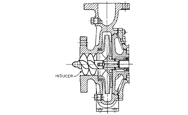
Inducers It is sometimes difficult or impossible to provide the required NPSH for an
otherwise acceptable pump. Besides normal industrial situations that might produce a
very low available NPSH, the need to keep the weight down in aircraft and rocket liquid-
propellant pumps has led to high rotative speeds, which, for typical values of NPSH, pro-
duce extremely high suction specific speeds. The performance-NPSH required by the
impeller under these circumstances can be provided by a small, axial-flow booster pump,
called an inducer, placed ahead of the first-stage impeller
39
. Inducers are designed to oper-
ate with very low NPSH and to provide enough head to satisfy the NPSH required by the
impeller. In fact, long stable cavities are established on the suction sides of the long,
lightly-loaded blades of an inducer, which enable it to operate at about twice the suction
specific speed of a conventional impeller
40,41
. At lower than normal flow rates, however,
inducers readily produce swirling, destabilizing backflow at the inlet, which can cause
excessive pump vibration in high-head pumps.These instabilities can be overcome by var-
ious passive design features, such as that described in Reference 39.
The inducers described in Reference 42 (Figure 30) have “constant lead” helical blades.
They contribute not more than 5% of the total pump head. Although the efficiency of the
inducer alone is low, the reduction in overall pump efficiency is not significant. Because
this type of inducer causes prerotation, a careful match between inducer and suction
impeller is required. In vertical multistage pumps, where a long shaft can be better sup-
ported, a vaned diffuser may be inserted between the inducer and the first-stage impeller.
Such an arrangement is very beneficial for operation at reduced flow rate. Reference 42
shows that a suitable inducer-impeller combination can operate at about 50% of the NPSH
required for the impeller alone at flow rates not exceeding the normal value. The NPSH
requirement increases rapidly for flow rates above normal. Unless a variable-lead inducer
is used
32, 39
, operation in this range should be avoided.
Entrained Air Air or other gases may enter the impeller inlet from several sources. The
immediate effect usually will be a drop in pump pressure rise, flow rate, and power. This
will be followed by loss of prime if more gas is present than the impeller can handle. A
typical limit for commercial industrial pumps is an inlet gas-to-liquid volume fraction
(GVF) of 0.03, although specialty pumps such as those used in aircraft (Section 9.19) can
handle higher GVF. See also Reference 9, Section 2.1. Air may be released from solution
or enter through leaks in the suction piping. Stuffing box air leakage may be prevented
by lantern rings supplied with liquid from the pump discharge. If the pump takes water
from a sump with a free surface, a vortex may form from the free surface to the impeller
inlet. The remedy may be the introduction of one or more baffle plates or even major
changes in the sump. For information on proper sump design and the prevention of air-
entraining vortices, see Sections 10.1 and 10.2, pp. 457 and 460 of Reference 7, and Ref-
erence 43. It is sometimes permissible to inject a small amount of air into the pump
2.3.1 CENTRIFUGAL PUMPS: GENERAL PERFORMANCE CHARACTERISTICS 2.359
FIGURE 30 Pump fitted with inducer (Reference 42)
suction to reduce the noise and damage from cavitation caused by inadequate NPSH or
recirculation in the impeller (see Subsection 2.3.2).
STARTING CENTRIFUGAL PUMPS ______________________________________
Priming
Centrifugal pumps usually are completely filled with the liquid to be pumped
before starting.When so filled with liquid, the pump is said to be primed. Pumps have been
developed to start with air in the casing and then be primed.
44
This procedure is unusual
with low-specific-speed pumps but is sometimes done with propeller pumps
12
. In many
installations, the pump is at a lower elevation than the supply and remains primed at all
times. This is customary for pumps of high specific speed and all pumps requiring a pos-
itive suction head to avoid cavitation.
Pumps operated with a suction lift may be primed in any of several ways. A relatively
inexpensive method is to install a special type of check valve, called a foot valve, on the
inlet end of the suction pipe and prime the pump by filling the system with liquid from any
available source. Foot valves cause undesirable frictional loss and may leak enough to
require priming before each starting of the pump.A better method is to close a valve in the
discharge line and prime by evacuating air from the highest point of the pump casing.
Many types of vacuum pumps are available for this service. A priming chamber is a tank
that holds enough liquid to keep the pump submerged until pumping action can be initi-
ated. Self-priming pumps usually incorporate some form of priming chamber in the pump
casing. Section 2.4 and Reference 7 may be consulted for further details.
Torque Characteristics of Drivers Centrifugal pumps of all specific speeds usually
have such low starting torques (turning moments) that an analysis of the starting phase
of operation seldom is required. Steam and gas turbines have high starting torques, so no
special starting procedures are necessary when they are used to drive pumps. If a pump
is directly connected to an internal combustion engine, the starting motor of the engine
should be made adequate to start both driver and pump. If the starter does not have
enough torque to handle both units, a clutch must be provided to uncouple the pump until
the driver is started.

2.360 CHAPTER TWO
Electric motors are the most commonly used drivers for centrifugal pumps. Direct cur-
rent motors and alternating current induction motors usually have ample starting torque
for all pump installations, provided the power supply is adequate. Many types of reduced
voltage starters are available
7
to limit the inrush current to safe values for a given power
supply. Synchronous motors are often used with large pumps because of their favorable
power-factor properties.They are started as induction motors and run as such up to about
95% of synchronous speed. At this point, dc field excitation is applied and the maximum
torque the motor can then develop is called the poll-in torque, which must be enough to
accelerate the motor and connected inertia load to synchronous speed in about 0.2 s if syn-
chronous operation is to be achieved. Centrifugal pumps usually require maximum torque
at the normal operating point, and this should be considered in selecting a driver, partic-
ularly a synchronous motor, to be sure that the available pull-in torque will bring the unit
to synchronous speed.
Torque Requirements of Pumps The torque, or turning moment, for a pump may be
estimated from the power curve in USCS units by
(25)
and in SI units by
where M pump torque, lb ft (N m)
P power, hp (kW)
n speed, rpm
Equation 25 makes no allowance for accelerating the rotating elements or the liquid in
the pump. If a 10% allowance for accelerating torque is included, the constant should be
correspondingly increased. The time t required to change the pump speed by an amount
n n
2
n
1
is given by
(26)
where t time, s
I moment of inertia (flywheel effect) of all rotating elements of driver, pump,
and liquid, lb ft (kg m
2
)
n change in speed, rpm
k 307 in USCS (9.549 in SI)
M
m
driver torque, lb ft (N m)
M pump torque, lb ft (N m) (Eq. 25)
The inertia I of the driver and pump usually can be obtained from the manufacturers
of the equipment. The largest permissible n for accurate calculation will depend on how
rapidly M
m
and M vary with speed. The quantity M
m
M should be nearly constant over
the interval n if an accurate estimate of t is to be obtained. Torque-speed characteris-
tics of electric motors may be obtained from the manufacturers.
Horizontal-shaft pumps fitted with plain bearings and packed glands require a break-
away torque of about 15% of M
n
, the torque at the normal operating point, to overcome the
static friction. This may be reduced to about 10% of M
n
if the pump is fitted with antifric-
tion bearings. The breakaway torque may be assumed to decrease linearly with speed to
nearly zero when the speed reaches 15 to 20% of normal. Construction of torque-speed
curves requires a knowledge of the pump characteristics at normal speed as well as details
of the entire pumping system. Some typical examples taken from Reference 7 are given
¢t
I¢n
k1M
m
M2
M
9549P
n
M
5252P
n
2.3.1 CENTRIFUGAL PUMPS: GENERAL PERFORMANCE CHARACTERISTICS 2.361
below. The following forms of the affinity laws (Eqs. 12) are useful in constructing the var-
ious performance curves:
(27)
(28)
(29)
(30)
where Q flow rate
n speed
H head
P power
M torque
in any consistent units of measure.After speeds n
1
and n
2
are chosen, the subscripts 1 and
2 refer to corresponding points on the characteristic curves for these speeds.
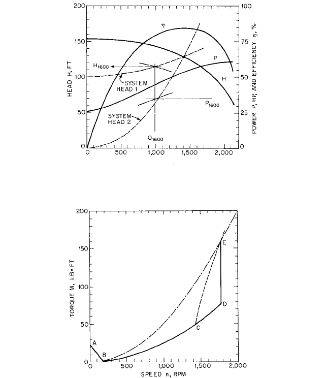
Low-Specific-Speed Pumps Figure 31 shows the constant-speed characteristics of a
pump having n
s
1740 (0.64) at best efficiency. This pump usually would be started with
a valve in the discharge line closed. During the starting phase, the pump operates at shut-
off with P
1
25.8 hp (19.2 kW) and n
1
1770 rpm. Then, by Eq. 25, M
1
76.6 lb ft (103.9
N m). These values may be used in Eq. 30 to evaluate starting torques M
2
at as many
speeds n
2
as desired and plotted in Figure 32 as curve BCD. Section AB of the starting
torque curve is an estimate of the breakaway torque. If the discharge valve is now opened,
the speed remains nearly constant but the torque increases as the capacity and power
increase. If the normal operating point is Q 1400 gpm (88.3 l/s) and P
n
53.2 hp (39.7
kW), the motor torque will be M
n
158 lb ft (214 N m) by Eq. 25. The vertical line DE
in Figure 32 shows the change in torque produced by opening the discharge valve.
Instead of starting the pump with the discharge valve closed, let the pump be started with
a check valve in the discharge line held closed by a static head of 100 ft (30.5 m). The fric-
tional head in the system may be represented by kQ
2
. The value of k may be estimated from
the geometry of the system or from a frictional-loss measurement at any convenient flowrate
Q, preferably near the normal capacity Q
n
. In this example, Q
n
1400 gpm (88.33 l/s) and k
14.4/10
6
(0.00109). The curve labeled system head 1 in Figure 31 was computed from H
100 (14.4/10
6
)Q
2
ft (H 30.48 0.00109Q
2
m) and intersects the head curve at H 128 ft
(39.01 m) and Q
n
1400 gpm (88.33 l/s). The normal shutoff head is H
1
153 ft (46.6 m) at
n
1
1770 rpm. By Eq. 28, the pump will develop a shutoff head H
2
100 ft (30.5 m) at n
2
1430 rpm. By Eq. 30, the torque at 1430 rpm will be 50 lb ft (68 N m), corresponding to
point C in Figure 32. The portion ABC of the starting torque curve has already been con-
structed. Trial-and-error methods must be used to obtain the portion ABC of the starting
torque curve.
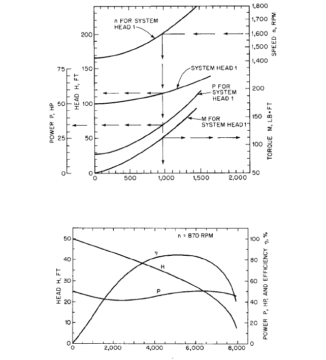
The auxiliary curves in Figure 33 are useful in constructing the CE portion of the start-
ing torque curve. Select a value of n
2
intermediate between 1427 and 1770 rpm, say n
2
1600 rpm. In Figure 31, read values of Q
1
, H
1
, and P
1
for speed n
1
1770 rpm. By Eqs. 27
and 28, determine values of Q
2
and H
2
and plot as shown in Figure 31 until an intersection
with the system-head 1 curve is obtained that provides Q
1600
corresponding to n 1600
rpm. By Eq. 29, determine value of P
2
and plot as shown in Figure 31 until an intersection
is obtained with the Q
1600
line which provides P
1600
corresponding to n 1600 rpm. Eq. 34
is now used to obtain M
1600
, which is one point on the desired starting torque curve. The
process is repeated for various speeds n
2
until the curve CE in Figure 32 can be drawn. The
M
2
M
1
a
n
2
n
1
b
2
P
2
P
1
a
n
2
n
1
b
3
H
2
H
1
a
n
2
n
1
b
2
H
1
a
Q
2
Q
1
b
2
Q
2
Q
1
n
2
n
1
2.362 CHAPTER TWO
FLOW RATE Q, GPM
FIGURE 31 Characteristics of a 6-by-8 double-section pump at 1770 rpm (ft 0.3048 = m; gpm 0.06309 = l/s;
hp 0.7457 = kW) n
s
= 1,740 (
s
= 0.64) (Reference 7)
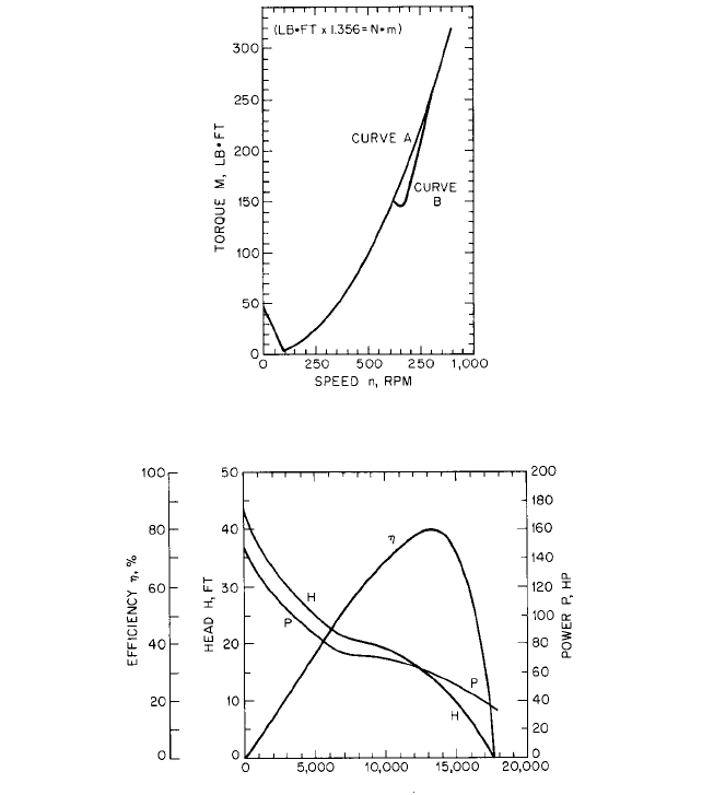
FIGURE 32 Torque characteristics of 6-by-8 pump shown in Figure 31 (lb • ft 1.356 = N • m) (Reference 7)
complete starting torque curve for this example is ABCE in Figure 31, with steady-state
operation at point E.
Assume that the pump of the preceding examples is installed in a system having zero
static head but a long pipeline with friction head given by H (65.4/10
6
)Q
2
ft (H
0.00500Q
2
m), as shown in Figure 31 by the curve labeled system head 2. The valve in
the discharge line is assumed to open instantaneously when power is first applied to the
pump. The procedure described to construct curve CE of the preceding example must
now be used together with the system-head 2 curve of Figure 31 to obtain the curve BE
of Figure 32. The complete starting torque curve for this example is ABE in Figure 32,
with steady-state operation at point E.
The inertia of the fluid in the system was neglected in solving the previous examples.
Some of the power must be used to accelerate the liquid, and this may be appreciable in the
case of a long pipeline. Low-specific speed pumps, which are used with long pipelines, have
2.3.1 CENTRIFUGAL PUMPS: GENERAL PERFORMANCE CHARACTERISTICS 2.363
FLOW RATE Q, GPM
FIGURE 33 Analysis of 6-by-8 pump shown in Figure 41 (ft 0.3048 = m; gpm 0.06309 = l/s; lb • ft 1.356 =
N
• m; hp 0.7457 = kW) (Reference 7)
FLOW RATE Q, GPM
FIGURE 34 Characteristics of a 16-in (40.6cm) volute pump with mixed-flow impeller with flat power
characteristic (ft 0.3048 = m; gpm 0.06309 = l/s; hp 0.7457 = kW). n
s
= 4570 (
s
= 1.672) (Reference 7)
rising power curves with minimum power at shutoff and maximum power at normal flow
rate. Experience has shown that the starting torque-speed curves computed by neglecting
the inertia of the liquid are conservative, so inertia effects need not be included. The iner-
tia effect of the liquid does slow the starting operation. If the time required to reach any
event, such as a particular speed or flow rate, is required, the inertia of the liquid should
be considered, but including it greatly increases the difficulty of computation. References
45 through 48 give general methods for handling problems involving liquid transients.
High-specific-speed pumps have falling power flow rate curves with maximum power
at shutoff and minimum power at normal flow rate. Neglecting the inertia of the liquid
probably will result in too low a value for the computed starting torque for such pumps. If
liquid inertia is to be included, consult References 44 to 47 and Section 8.1.
MEDIUM- AND HIGH-SPECIFIC-SPEED PUMPS Figure 34 shows constant-speed characteristics
for a medium-specific-speed pump, n
s
4570 (1.672) at best efficiency. The shutoff power
2.364 CHAPTER TWO
FIGURE 35 Torque characteristics of pump shown in Figure 34 (Reference 7)
FLOW RATE Q, GPM
FIGURE 36 Characteristics of a 30-in (76.2-cm) discharge propeller pump at 700 rpm (ft 0.1048 = m; gpm
0.06309 = l/s; hp 0.7457= kW). n
s
= 12,000 (
s
= 4.391) (Reference 7)
is the same as the power at best efficiency, and the starting torque-speed curve is but lit-
tle affected by the method of starting, as shown by Figure 35.
Figure 36 shows the constant-speed characteristics of a high-specific-speed propeller
pump, n
s
12,000 (4.391) at best efficiency. Figure 37 shows the starting torque-speed
curve when the pump is started against a static head of 14 ft (4.3 m) and a friction head
of 1 ft (0.3 m) at Q
n
12,500 gpm (789 l/s). The system was assumed full of water with a
closed check valve at the outlet end of the short discharge pipe. The methods of computa-
tion for Figures 35 and 37 were the same as for Figure 32.
Sometimes propeller pumps are started with the pump submerged but with the dis-
charge column filled with air. In such a case, the torque-time characteristic for the driver
must be known and a step-by-step calculation carried out. If the discharge column is a
siphon initially filled with air, the starting torque may exceed the normal running torque
during some short period of the starting operation. If the pump is driven by a synchronous