Pump Handbook by Igor J. Karassik, Joseph P. Messina, Paul Cooper, Charles C. Heald - 3rd edition
Подождите немного. Документ загружается.

2.3.1 CENTRIFUGAL PUMPS: GENERAL PERFORMANCE CHARACTERISTICS 2.365
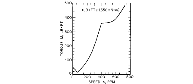
FIGURE 37 Torque characteristics of pump shown in Figure 36 (Reference 7)
motor, it is particularly important to investigate the starting torque in the range of 90 to
100% of normal speed to make sure that the pull-in torque of the motor is not exceeded.
For additional information regarding starting high-specific-speed pumps discharging
through long and large diameter systems, see Section 8.1.
Miscellaneous Requirements Pumps handling hot liquids should be warmed up to
operating temperature before being started unless they have been especially designed for
quick starting. Failure to do this may cause serious damage to wearing rings, seals, and
any hydraulic balancing device that may be present. A careful check of the installation
should be made before starting new pumps, pumps that have had a major overhaul, or
pumps that have been standing idle for a long time. It is very important to follow the man-
ufacturer’s instructions when starting boiler-feed pumps. If these are unavailable, Refer-
ence 7 may be consulted. Ascertain that the shaft is not frozen, that the direction of
rotation is correct, preferably with the coupling disengaged, and that bearing lubrication
and gland cooling water meet normal requirements. Failure to do this may result in dam-
age to the pump or driver.
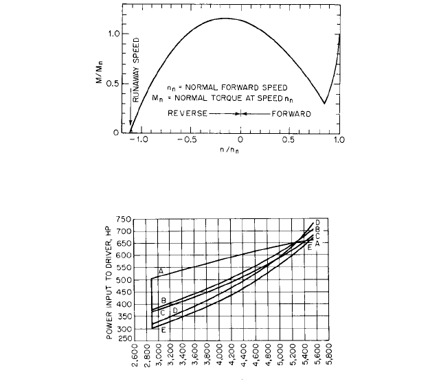
A pump may run backwards at runaway speed if the discharge valve fails to close follow-
ing shutdown. Any attempt to start the pump from this condition will put a prolonged over-
load on the motor. Figure 38 shows one example of the torque-speed transient for a pump, n
s
1700 (0.622), started from a runaway reversed speed while normal pump head was main-
tained between the section and discharge flanges. In most practical cases, water hammer
effects would make this transient even more unfavorable than Figure 38 indicates.The dura-
tion of such a transient will always be much longer than the normal starting time, and so pro-
tective devices would probably disconnect the motor from the power supply before normal
operation could be achieved. Consult Section 8.1 for additional information on this subject.
REGULATION OF FLOW RATE__________________________________________
Flow rate variation ordinarily is accomplished by a change in pump head, speed, or both
simultaneously. The flow rate and power input of pumps with specific speeds up to about
4000 (1.464) double suction increase with decreasing head, so the drivers of such pumps
may be overloaded if the head falls below a safe minimum value. Increasing the head of
high-specific-speed pumps decreases the flow rate but increases the power input. The dri-
vers of these pumps should either be able to meet possible load increases or be equipped
with suitable overload protection. Flow rate regulation by the various methods given
below may be manual or automatic (see also References 1, 7, 12, 34 and 49).
2.366 CHAPTER TWO
FIGURE 38 Torque characteristics of a double-suction pump, n
s
L 1700 (0.64), from reversed runaway speed to
normal forward speed (Reference 7)
FLOW RATE Q, GPM
FIGURE 39 Power requirements of two double-suction pumps in series operated at constant head and variable
flow rate. Total H
n
= 382 ft (116 m) for both pumps at 1800 rpm (gpm 0.06309 = l/s hp 0.7457 = kW) (Reference
50). Curve AA: constant speed with discharge throttling. Curve BB: synchronous motor with variable-speed
hydraulic coupling on each pump. Curve CC: variable-speed wound-rotor induction motor. Curve DD: dc motor with
rectifier and shunt field control. Curve EE: synchronous motor with variable-speed constant-efficiency mechanical
speed reducer
Discharge Throttling This is the cheapest and most common method of flow rate mod-
ulation for low- and medium- specific-speed pumps. Usually its use is restricted to such
pumps. Partial closure of any type of valve in the discharge line will increase the system
head so the system-head curve will intersect the pump head curve at a smaller flow rate,
as shown in Figure 40. Discharge throttling moves the operating point to one of lower effi-
ciency, and power is lost at the throttle valve. This may be important in large installa-
tions, where more costly methods of modulation may be economically attractive.Throttling
to the point of cutoff may cause excessive heating of the liquid in the pump. This may
require a bypass to maintain the necessary minimum flow or use of different method of
modulation. This is particularly important with pumps handling hot water or volatile liq-
uids, as previously mentioned. Refer to Section 8.2 for information regarding the sizing of
a pump bypass.
Suction Throttling If sufficient NPSH is available, some power can be saved by throt-
tling in the suction line. Jet engine fuel pumps frequently are suction throttled
5
because
discharge throttling may cause overheating and vaporization of the liquid.At very low flow
rate, the impellers of these pumps are only partly filled with liquid, so the power input and
temperature rise are about one-third the values for impellers running full with discharge
throttling.The capacity of condensate pumps frequently is submergence-controlled,
7
which
2.3.1 CENTRIFUGAL PUMPS: GENERAL PERFORMANCE CHARACTERISTICS 2.367
is equivalent to suction throttling. Special design reduces cavitation damage of these
pumps to a negligible amount, the energy level (Section 2.1) being quite low.
Bypass Regulation All or part of the pump flow may be diverted from the discharge
line to the pump suction or other suitable point through a bypass line. The bypass may
contain one or more metering orifices and suitable control valves. Metered bypasses are
commonly used with boiler-feed pumps for reduced-flow operation, mainly to prevent over-
heating. There is a considerable power saving if excess capacity of propeller pumps is
bypassed instead of using discharge throttling.
Speed Regulation This can be used to minimize power requirements and eliminate
overheating during flow rate modulation. Steam turbines and internal combustion
engines are readily adaptable to speed regulation at small extra cost. A wide variety of
variable-speed mechanical, magnetic, and hydraulic drives are available, as well as both
ac and dc variable-speed motors. Usually variable-speed motors are so expensive that they
can be justified only by an economic study of a particular case. Figure 39 shows a study
by Richardson
50
of power requirements with various drivers wherein substantial
economies in power may be obtained from variable-speed drives.
Regulation by Adjustable Vanes Adjustable guide vanes ahead of the impeller have
been investigated and found effective with a pump of specific speed n
s
5700 (2.086).
The vanes produced a positive prewhirl that reduced the head, flow rate, and efficiency.
Relatively little regulation was obtained from the vanes with pumps having n
s
3920
(1.204) and 1060 (0.39). Adjustable outlet diffusion vanes have been used with good suc-
cess on several large European storage pumps for hydroelectric developments. Pro-
peller pumps with adjustable-pitch blades have been investigated with good success.
Wide flow rate variation was obtained at constant head and with relatively little loss
in efficiency. These methods are so complicated and expensive that they have very lim-
ited application in practice. Reference 34 may be consulted for further discussion and
bibliography.
Air Admission Admitting air into the pump suction has been demonstrated as a means
of flow-rate regulation, with some savings in power over discharge throttling. Usually air
in the pumped liquid is undesirable, and there is always the danger that too much air will
cause the pump to lose its prime. The method has rarely been used in practice but might
be applicable to isolated cases.
PARALLEL AND SERIES OPERATION ___________________________________
Two or more pumps may be arranged for parallel or series operation to meet a wide range
of requirements in the most economical manner. If the pumps are close together, that is,
in the same station, the analysis given below should be adequate to secure satisfactory
operation. If the pumps are widely separated, as in the case of two or more pumps at
widely spaced intervals along a pipeline, serious pressure transients may be generated by
improper starting or stopping procedures. The analysis of such cases may be quite com-
plicated, and References 46 to 48 should be consulted for methods of solution.
Parallel Operation Parallel operation of two or more pumps is a common method of
meeting variable-flow-rate requirements. By starting only those pumps needed to meet
the demand, operation near maximum efficiency can usually be obtained. The head-flow
characteristics of the pumps need not be identical, but pumps with unstable characteris-
tics may give trouble unless operation only on the steep portion of the characteristic can
be assured. Care should be taken to see that no one pump, when combined with pumps
of different characteristics, is forced to operate at flows less than the minimum required
to prevent recirculation. See the discussion that follows on operation at other than nor-
mal flow rate. Multiple pumps in a station provide spares for emergency service and for
the downtime needed for maintenance and repair.
2.368 CHAPTER TWO
FLOW RATE Q, GPM
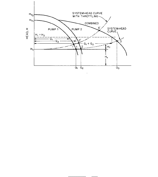
FIGURE 40 Head-flow curves of pumps operating in parallel
The possibility of driving two pumps from a single motor should always be considered,
as it usually is possible to drive the smaller pumps at about 40% higher speed than a sin-
gle pump of twice the capacity. The saving in cost of the higher-speed motor may largely
offset the increased cost of two pumps and give additional flexibility of operation.
One of the first steps in planning for multiple-pump operation is to draw the system-
head curve, as shown in Figure 40. The system head consists of the static head H
s
and the
sum H
f
of the pipe-friction head and the head lost in the valves and fittings (see Sections
8.1 and 8.2). The head curves of the various pumps are plotted on the same diagram, and
their intersections with the system-head curve show possible operating points. Combined
pump head curves are drawn by adding the flow rates of the various combinations of
pumps for as many values of the head as necessary. The intersection of any combined H-
Q curve with the system-head curve is an operating point. Figure 40 shows two pump
head curves and the combined curve. Points 1, 2, and 3 are possible operating conditions.
Additional operating points may be obtained by changing the speed of the pumps or by
increasing the system-head loss by throttling. Any number of pumps in parallel may be
included on a single diagram, although separate diagrams for different combinations of
pumps may be preferable.
The overall efficiency h of pumps in parallel is given by
(31)
where H head, ft (m)
sp. gr. specific gravity of the liquid
k 3960 USCS (0.1021 SI)
Q sum of the pump flow rates, gpm (l/s)
P total power supplied to all pumps, hp (W)
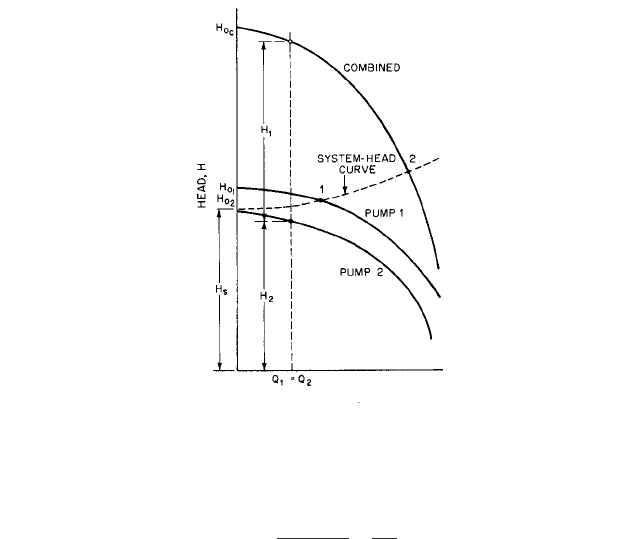
Series Operation Pumps are frequently operated in series to supply heads greater than
those of the individual pumps. The planning procedure is similar to the case of pumps in
parallel. The system-head curve and the individual head-flow curves for the pumps are
plotted as shown in Figure 41. The pump heads are added as shown to obtain the com-
bined pump head curve. In this example, Pump 2 operating alone will deliver no liquid
because its shutoff head is less than the system static head.
There are two possible operating points, 1 and 2, as shown by the appropriate inter-
sections with the system-head curve. As with parallel operation, other operating points
h
H1sp. gr.2
k
Q
P
2.3.1 CENTRIFUGAL PUMPS: GENERAL PERFORMANCE CHARACTERISTICS 2.369
FLOW RATE, Q
FIGURE 41 Head-flow curves of pumps operating in series
could be obtained by throttling or by changing the pump speeds. The overall efficiency of
pumps in series is given by
(32)
wherein the symbols are the same as for parallel operation. It is important to note that the
stuffing box pressure of the second pump is increased by the discharge pressure of the first
pump.This may require a special packing box for the second pump with leakoff to the suc-
tion of the first pump.The higher suction pressure may increase both the first cost and the
maintenance costs of the second pump.
OPERATION AT OTHER THAN THE NORMAL FLOW RATE___________________
Centrifugal pumps usually are designed to operate near the point of best efficiency, but
many applications require operation over a wide range of flow rates, including shutoff, for
extended periods of time. Pumps for such service are available but may require special
design and construction at higher cost. Noise, vibration, and cavitation may be encoun-
tered at low flow rates. Large radial shaft forces at shutoff as well as lack of through flow
to provide cooling may cause damage or breakage to such parts as shafts, bearings, seals,
glands, and wearing rings of pumps not intended for such service. Some of the phenomena
associated with operation at other than normal flow rate are described below.
Recirculation There is a small flow from impeller discharge to suction through the
wearing rings and any hydraulic balancing device present. This takes place at all flow
rates, but does not usually contribute to raising the liquid temperature very much unless
operation is near shutoff.
When the flow rate has been reduced by throttling (or as a result of an increase in sys-
tem head), a secondary flow called recirculation begins. Recirculation is a flow reversal due
to separation at the suction and at the discharge tips of the impeller vanes. All impellers
h
Q1sp. gr.2
k
H
P
2.370 CHAPTER TWO
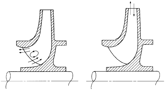
FIGURE 42 Suction recirculation
FIGURE 43 Discharge recirculation
have a critical flow rate at which recirculation occurs. The flow rates at which suction and
discharge recirculation begin can be controlled to some extent by design, but recirculation
cannot be eliminated (see Figure 6 in Section 2.1).
Suction recirculation is the reversal of flow at the impeller eye. A portion of the flow is
directed out of the eye at the eye diameter, as shown in Figure 42 , and travels upstream
with a rotational velocity approaching the peripheral velocity of the diameter. A rotating
annulus of liquid is produced upstream from the impeller inlet, and through the core of
this annulus passes an axial flow corresponding to the output flow rate of the pump. In
pumps equipped with long, straight suction nozzles but no suction elbow, this rotating
fluid has been detected over considerable distances upstream from the impeller eye. Suc-
tion pressures measured at wall taps where this phenomenon is present are always higher
than the true average static pressure across the measuring section. This means that the
pump head as determined from wall taps is less than it would be if true average static
pressures were measured. The high shear rate between the rotating annulus and the axial
flow through the core produces vortices that form and collapse, producing noise and cavi-
tation in the suction of the pump.
Discharge recirculation is the reversal of flow at the discharge tips of the impeller
blades, as shown in Figure 43. The high shear rate between the inward and outward rel-
ative velocities produces vortices that cavitate and can attack the pressure side of the
blades. This phenomenon, which tends to occur at a lower flow rate than the highest Q
for suction recirculation, also involves stalled flow from the diffuser vanes or volute
tongue(s). Separated reversed flow recirculates and emerges from these vane systems
back into the impeller with negative swirl (that is, swirl opposite to the direction of
rotation). The impeller must expend significant power to redirect the portion of this
fluid (that reenters it) out again
—
with positive swirl. As discussed in Section 2.1, the
portion of this backflow from the diffuser or volute that enters the spaces outside the
impeller shrouds and adjacent to the casing walls has the potential to reverse the axial
thrust of the impeller, and this reversal can fluctuate if the backflow is unsteady (as
separated, recirculating flow normally is) and not always feeding the same side of the
impeller.
The flow rate Q
sr
below which suction recirculation occurs is directly related to the
design suction-specific speed S of the pump. The higher the suction-specific speed, the
closer will be the beginning of recirculation to the flow rate at best efficiency. Figure 44
shows the relation between the suction specific speed and suction recirculation for pumps
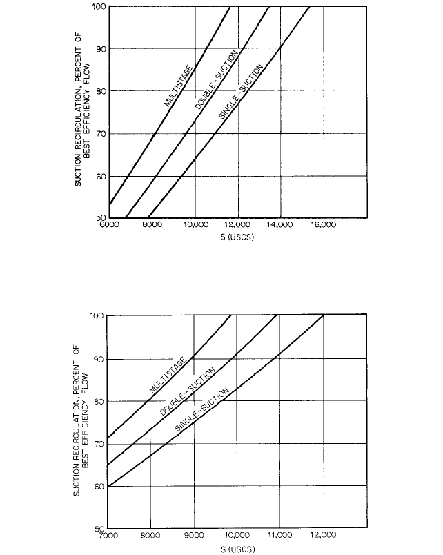
2.3.1 CENTRIFUGAL PUMPS: GENERAL PERFORMANCE CHARACTERISTICS 2.371
FIGURE 44 Influence of the design value of suction specific speed S on the flow rate Q
SR
below which suction
recirculation occurs. 500 6 n
s
6 2500; (0.18 6
s
6 0.91) for single-suction or one side of a double-suction impeller.
The ordinate is Q
SR
/Q
BEP
in percent. (To obtain
ss
, divide S by 2733.)
FIGURE 45 Influence of the design value of suction specific speed S on the flow rate Q
SR
below which suction
recirculation occurs. 2500 6 n
s
6 10,000; (0.91 6
s
6 3.66) for single-suction or one side of a double-suction
impeller. The ordinate is Q
SR
/Q
BEP
in percent. (To obtain
ss
, divide S by 2733.)
up to 2500 (0.915) specific speed, and Figure 45 shows the same relation for pumps up to
10,000 (3.659) specific speed.
Despite the existence of suction and discharge recirculation, the mechanical response
of the pump will not be serious unless the energy level is high. In other words, most pumps
can indeed be operated at Q 6 Q
SR
. The minimum flow rate or simply “minimum flow” Q
min
is quantified in Section 2.1. As energy level is increased, Q
min
approaches Q
SR
in the limit.
Examples of the difference between Q
min
and Q
SR
are as follows: For water pumps rated at
2500 gpm (158 l/s) and 150 ft (45.7 m) total head or less, the minimum operating flows can

2.372 CHAPTER TWO
be as low as 50% of the suction recirculation values shown for continuous operation and
as low as 25% for intermittent operation. For hydrocarbons, the minimum operating flows
can be as low as 60% of the suction recirculation values shown for continuous operation
and as low as 25% for intermittent operation.
51, 52, 53
Temperature Rise Under steady-state conditions, friction and the work of compression
increase the temperature of the liquid as it flows from suction to discharge.A further tem-
perature increase may arise from liquid returned to the pump suction through wearing
rings, a balancing device, or a minimum-flow bypass line that protects the pump when
operating at or near shutoff.
Assuming that all heat generated remains in the liquid, the temperature rise is
(33)
where g/g
o
1 lbf/lbm; but when using SI units, g/g
o
is replaced by 9.80665 m/s
2
( g in the
SI system). T
c
is due to the compression of the liquid and is not a consequence of loss or
dissipation as is the term involving the pump efficiency h (see Section 2.1). As shown in
Reference 1 of Section 2.1, T
c
is 3°F per 1000 psi (0.24°C per MPa) of pump pressure rise
for hydrocarbon fuels. For boiler feedwater at 350°F (177°C), T
c
1.6°F per 1000 psi
(0.129°C per MPa), but it is much smaller for cold water. By consulting tables of properties
for the liquid phase of the fluid being pumped and assuming the compression process
between the actual inlet and discharge pressures to be isentropic, T
c
can be determined.
This is important if Eq. 33 is used to evaluate overall pump efficiency from temperature
rise measurements. T and T
c
are often of the same order of magnitude at BEP, and seri-
ous errors have been made by excluding T
c
from the efficiency computation. At very low,
off-BEP flow rates, T will be high in comparison to T
c
; so, the latter can be safely ignored
in temperature rise calculations at such low-efficiency conditions.
In practice, determination of efficiency from T-measurements is accomplished by the
direct thermodynamic method
54
, rather than by the T
c
-method. Both approaches are
based on the definition of pump efficiency as the ratio of an isentropic rise of total enthalpy
( gH) to the actual rise of total enthalpy (Eq. 1 of Section 2.1), allowances being made
for the usually small external power losses that do not appear in the pumped fluid (such
as bearing drag) and the similarly small effects of heat transferred between pump and
surroundings. In the direct thermodynamic method, the enthalpy rise h is found from the
chain rule,
the coefficients a and C
p
J being average values of the two partial derivatives as found from
tables of thermodynamic properties of the fluid. Values of these partial derivatives are con-
veniently tabulated for water in Reference 54.
General service pumps handling cold liquids may be able to stand a temperature rise as
great as 100°F (56°C). Most modern boiler-feed pumps may safely withstand a temperature
rise of 50°F (28°C). The NPSH required to avoid cavitation or to prevent flashing of hot liq-
uid returned to the pump suction may be the controlling factor. Minimum flow may be dic-
tated by other factors, such as recirculation and unbalanced radial and axial forces on the
impeller. Axial forces can be the controlling factor with single-stage double-suction pumps.
It is especially important to protect even small pumps handling hot liquids from oper-
ation at shutoff. This is usually done by providing a bypass line fitted with a metering ori-
fice to maintain the minimum required flow through the pump. In the case of boiler-feed
pumps, the bypass flow usually is returned to one of the feed-water the water heaters.
Unless especially designed for cold starting, pumps handling hot liquids should be warmed
up gradually before being put into operation.
Radial Thrust Ideally, the circumferential pressure distribution at the impeller exit is
uniform at the design condition (as explained in Section 2.1); however, it becomes non-
¢h
dh
310h>0p2
T
dp 10h>0T2
p
dT4 a¢p C
p
J¢T
¢T
gH 11 h2
g
o
C
p
hJ
¢T
c
2.3.1 CENTRIFUGAL PUMPS: GENERAL PERFORMANCE CHARACTERISTICS 2.373
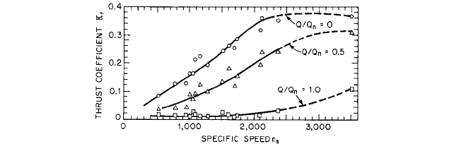
FIGURE 46 K
r
as a function of specific speed and flow rate for single-volute pumps (to obtain
s
, divide by 2733.)
(Reference 55)
uniform at off-BEP flow rates.An exception is that concentric collecting configurations will
produce non-uniform pressure distributions at the BEP. Any non-uniformity leads to a
radial force on the pump shaft called the radial thrust or radial reaction. The radial thrust
F
r
in pounds (newtons) is
(34)
where k 0.433 USGS (9790 SI)
K
r
experimentally determined coefficient
sp. gr. specific gravity of the liquid pumped (equal to unity for cold water)
H pump head, ft (m)
D
2
outside diameter of impeller, in (m)
b
2
breadth of impeller at discharge, including shrouds, in (m)
Values of K, determined by Agostinelli et al.
55
for single-volute pumps are given in
Figure 46 as functions of specific speed and flow rate.The magnitude and direction of F
r
on the pump shaft may be estimated from Figure 47 , but Eq. 34 probably will be more
accurate for determining the magnitude of the force. The radial thrust usually is mini-
mum near Q Q
n
,the flow rate at best efficiency, but rarely goes completely to zero.
Near shutoff, F
r
usually is maximum and may be a considerable force on the shaft in
high-head pumps.
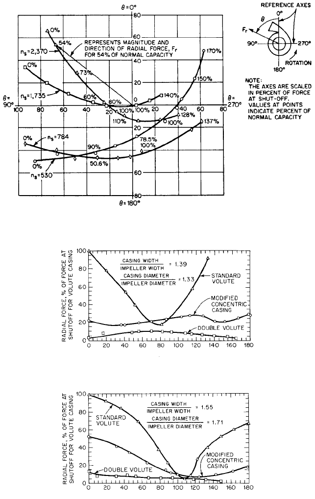
The radial thrust can be made much smaller throughout the entire flow-rate range by
using a double volute (twin volute) or a concentric casing. These designs should be con-
sidered, particularly if the pump must operate at small flow rates. Figures 48 to 50 com-
pare radial forces generated by three types of casings: a standard volute, a double volute,
and a modified concentric casing. The latter casing was concentric with the impeller for
270° from the tongue and then enlarged in the manner of a single volute to form the dis-
charge nozzle. The magnitude and direction of F
r
on the pump shaft for the modified con-
centric casing may be estimated from Figure 51.The direction of F
r
on the pump shaft with
a double volute was somewhat random but in the general vicinity of the casing tongue.
Radial forces on pumps fitted with diffuser vanes usually are rather small, although they
may be significant near shutoff due to stall in some of the passages and not in others.
EXAMPLE Consider a single-stage centrifugal pump, n
s
2000 (0.732) at best effi-
ciency, handling cold water, sp. gr. 1.0. Estimate the radial thrust on the impeller at
half the normal flow rate when fitted with (a) a single volute, (b) a modified concentric
casing, and (c) a double volute. Impeller dimensions are D
2
15.125 in (38.4 cm) and
b
2
2.5 in (6.35 cm). The shutoff head is H 252 ft (76.8 m), and the head at half
capacity is H 244 ft (74.4 m).
F
r
kK
r
1sp. gr.2HD
2
b
2
2.374 CHAPTER TWO
FIGURE 47 Polar plot showing direction of resultant radial forces for single-volute pumps at various flow rates
(“capacities”) and specific speeds. To obtain
s
, divide by 2733. (Reference 55)
FLOW RATE, % OF NORMAL
FIGURE 48 Comparison of the effect of three casing designs on radial forces for n
s
= 1165 (0.426) (Reference 55)
FLOW RATE, % OF NORMAL
FIGURE 49 Comparison of the effect of three casing designs on radial forces for n
s
= 2120 (0.776) (Reference 55)