Pump Handbook by Igor J. Karassik, Joseph P. Messina, Paul Cooper, Charles C. Heald - 3rd edition
Подождите немного. Документ загружается.

2.3.1 CENTRIFUGAL PUMPS: GENERAL PERFORMANCE CHARACTERISTICS 2.335
FLOW RATE
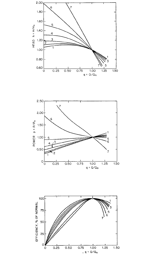
FIGURE 8 Head curves for several specific speeds, as defined in Table 2 (Reference 12)
FLOW RATE
FIGURE 9 Power curves for several specific speeds, as defined in Table 2 (Reference 12)
FLOW RATE
FIGURE 10 Efficiency curves for several specific speeds, as defined in Table 2 (Reference 12).
2.336 CHAPTER TWO
UNIVERSAL SPECIFIC SPEED Ω
S
0
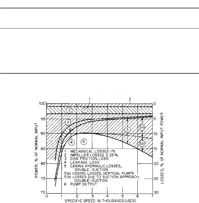
FIGURE 11 Power balance for double-suction pumps at best efficiency (Reference 12)
TABLE 2 Characteristic curves as a function of specific speed (Figures 8, 9, and 10)
Universal Impeller
Curve Number on USCS Specific Metric (SI) Specific Suction
Figures 8 , 9 , and 10 Speed n
s
Specific Speed n
q
Speed
s
Configuration
1 900 17 0.33 Double
2 1500 29 0.55 Double
3 2200 43 0.80 Double
4 3000 58 1.10 Double
5 4000 77 1.46 Double
6 5700 110 2.09 Single
7 9200 178 3.37 Single
and wear increase with increasing speed, particularly if the liquid contains solid particles
in suspension. The danger of cavitation damage usually increases with increasing speed
unless certain suction requirements can be met, as described later.
Effects of Specific Speed Figues 6 and 11 show that maximum efficiency is obtained
in the range 2000 (0.73) 6 n
s
6 3000 (1.10), but this is not the only criterion. Pumps for
high heads and small flow rates occupy the range 500 (0.18) 6 n
s
6 1000 (0.37). At the
other extreme, pumps for very low heads and large flow rates may have n
s
15,000 (5.49)
or higher. For given head and flow rate, the pump having the highest specific speed that
will meet the requirements probably will be the smallest and least expensive. However,
Figure 9 of Section 2.1 shows that it will run at the highest speed and be subject to max-
imum wear and cavitation damage, as previously mentioned.
Effects of Clearance
WEARING-RING CLEARANCE Details of wearing-ring construction are given in Subsection
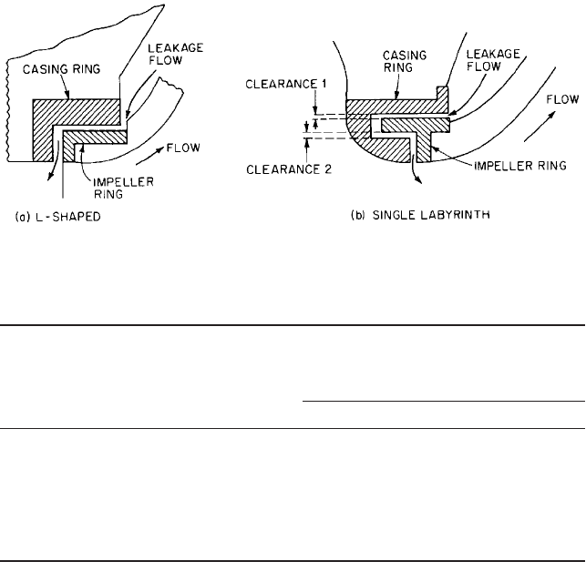
2.2.1. Schematic outlines of two designs of rings are shown in Figure 12. The L-shaped
construction shown in Figure 12a is very widely used with the close clearance between
the cylindrical portions of the rings. Leakage losses increase and pump performance
2.3.1 CENTRIFUGAL PUMPS: GENERAL PERFORMANCE CHARACTERISTICS 2.337
FIGURE 12A and B Typical wearing rings
TABLE 3 Effects of increased wearing-ring clearance on centrifugal pump
performance
Percent of values Percent of values
at shutoff at best efficiency
Specific Design Ring
with normal with normal
speed head, clearance, % of
ring clearance ring clearance
n
s
(
s
) ft (m) normal value QH P h H
0
P
0
2100 (0.77) 63 (19.2) 178 100 98.3 98.9 99.4 97.0 100
. . . . . . 356 100 97.5 99.0 98.5 93.6 98.2
. . . . . . 688 100 96.0 98.9 97.1 91.2 94.8
. . . . . . 1375 100 94.3 97.4 96.8 88.8 92.5
3500 (1.28) 65 (19.8) 354 100 90.0 99.1 90.8 85.0 96.2
4300 (1.57) 41(12.5) 7270 62 65.5 81.7 49.8 44.3 106
4800 (1.76) 26 (7.9) 5220 96 78.8 89.2 84.8 78.2 83.3
Source: Flowserve Corporation
falls off as the rings wear. Table 3 shows some of the effects of increasing the clearance
of rings similar to Figure 12a.
The labyrinth construction shown in Figure 12b has been used to increase the leakage
path without increasing the axial length of the rings. If the pressure differential across
these rings is high enough, the pump shaft may take on lateral vibrations with relatively
large amplitude and long period, which can cause serious damage. One remedy for these
vibrations is to increase clearance 2 in Figure 12b relative to clearance 1, at the expense of
an increased leakage flow. High-pressure breakdown through plain rings may cause vibra-
tion,
10
but this is not usually a serious problem. It is considered good practice to replace or
repair wearing rings when the nominal clearance has doubled. The presence of abrasive
solids in the liquid pumped may be expected to increase wearing-ring clearances rapidly.
VANE-TIP CLEARANCE Many impellers are made without an outer shroud and rely on close
running clearances between the vane tips and the casing to hold leakage across the vane
tips to a minimum. Although this construction usually is not used with pumps having spe-
cific speeds less than about 6000 (2.20), Wood et al.
11
have reported good results with semi-
open impellers at 1800 (0.66) n
s
4100 (1.50). It appears that both head and efficiency
increase with decreasing tip clearance and are quite sensitive to rather small changes in
clearance. Reducing the tip clearance from about 0.060 in (1.5 mm) to about 0.010 in (0.25
mm) may increase the efficiency by as much as 10%. Abrasive solids in the liquid pumped
probably will increase tip clearances rapidly.

2.338 CHAPTER TWO
MODIFICATIONS TO IMPELLER AND CASING _____________________________
Diameter Reduction
To reduce cost, pump casings usually are designed to accommodate
several different impellers.Also, a variety of operating requirements can be met by chang-
ing the outside diameter of a given radial impeller. Eq. 6 shows that the head should be
proportional to (nD)
2
provided that the exit velocity triangles (Figure 2b) remain similar
before and after cutting, with w
2
always parallel to itself as u
2
is reduced. This can be
achieved if the impeller meridional exit area A
m,2
is the same before and after cutting
—
and
if the flow angle b
f,2
(Figure 15, Section 2.1) also stays the same. [b
f,2
would stay the same
if the blade angle b
2
( b
b,2
) does, the difference being due to slip velocity V
s
that should
also scale down with D.] For radial discharge impellers, area A
m,2
equals pDb
2
(minus blade
and boundary layer blockage) and requires that b
2
increase as D decreases. This is typical
of many impellers
—
as is constancy of b
2
over the cutting range
—
and, together with Eqs.
27–33 of Section 2.1, leads to the so-called “affinity laws” for predicting performance:
(12a)
(12b)
(12c)
which apply only to a given impeller with altered D and constant efficiency but not to a
geometrically similar series of impellers. The assumptions on which Eqs. 12 were based
are rarely if ever fulfilled in practice, so exact predictions by the equations should not be
expected. A common example is the low-n
s
radial discharge impeller with parallel radial
hub and shroud profiles over most of the path from inlet to exit (Figure 6). Here, A
m,2
decreases with cutting, and H falls more than would be predicted by Eq. 12b. [This type of
impeller is often found in multistage pumps, particularly those in which the designer, dri-
ven by cost reduction goals, has minimized a) the axial length occupied by each stage and
b) the number of stages, thereby pushing down the n
s
of the individual stage to the point
that a tolerable sacrifice in efficiency results.]
RADIAL DISCHARGE IMPELLERS
Impellers of low specific speed may be cut successfully pro-
vided the following items are kept in mind:
1. The angle b
2
may change as D is reduced, but this usually can be corrected by filing
the blade tips. (See the discussion on blade-tip filing that follows.)
2. Tapered blade tips will be thickened by cutting and should be filed to restore the orig-
inal shape. (See the discussion below on blade-tip filing.)
3. Bearing and stuffing box friction remain constant, but disk friction should decrease
with decreasing D.
4. The length of flow path in the pump casing is increased by decreasing D.
5. Because c
m1
is smaller at the reduced capacity, the inlet triangles no longer remain
similar before and after cutting, and local flow separation may take place near the
blade entrance tips.
6. The second right-hand term in Eq. 5 was neglected in arriving at Eqs. 12, but it may
represent a significant decrease in head as D is reduced.
7. Some blade overlap should be maintained after cutting. Usually the initial blade over-
lap decreases with increasing specific speed, so the higher the specific speed, the less
the allowable diameter reduction.
8. Diameter reductions greater than from 10 to 20% of the original full diameter of the
impeller are rarely made.
P
1
P
2
n
3
1
D
1
3
n
3
2
D
3
2
H
1
H
2
n
2
1
D
1
2
n
2
2
D
2
2
Q
1
Q
2
n
1
D
1
n
2
D
2

2.3.1 CENTRIFUGAL PUMPS: GENERAL PERFORMANCE CHARACTERISTICS 2.339
Most of the losses are approximately proportional to Q
2
, and hence to D
2
by Eq. 12.
Because the power output decreases approximately as D
3
, it is reasonable to expect the
maximum efficiency to decrease as the wheel is cut, and this often is the case. By Eq. 12
and the n
s
-definition (Eq. 38a of Section 2.1), the product n
s
D should remain constant so
the specific speed at best efficiency increases as the wheel diameter is reduced (Table 4).
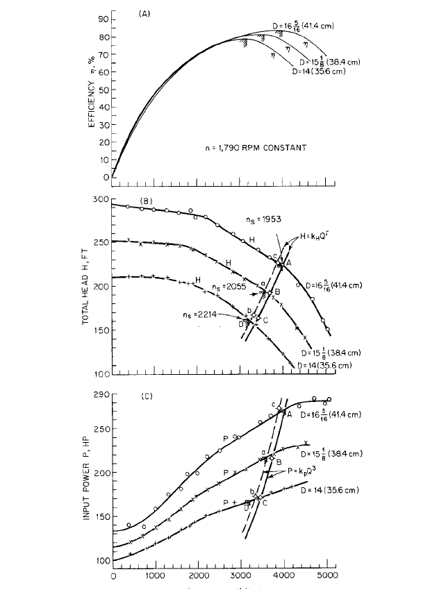
The characteristics of the pump shown in Figure 13 may be used to illustrate reduction
of diameter at constant speed. Starting with the best efficiency point and D 16 in (41.4
cm), let it be required to reduce the head from H 224.4 to H¿ 192.9 ft (68.4 m to 58.8 m)
and to determine the wheel diameter, capacity, and power for the new conditions.
Because the speed is constant, Eqs. 12 may be written
(13)
where k
H
and k
p
may be obtained from the known operating conditions at D l6 in (41.4
cm). Plot a few points for assumed capacities and draw the curve segments as shown by
the solid lines in Figures 13b and 13c. Then, from Eqs. 12
(14a)
(14b)
from which D 15 in (38.4 cm), Q 3709 gpm (234 l/s), and P¿ 215.5 hp (160.7 kW). In
Figure 13, the initial conditions were at points A and the computed conditions after cut-
ting at points B. The test curve for D 15 in (38.4 cm) shows the best efficiency point a
at a lower flow rate than predicted by Eqs. 14, but the head curve satisfies the predicted
values very closely. The power prediction was not quite as good.Table 4 and Figure 13 give
actual and predicted performance for three impeller diameters.The error in predicting the
best efficiency point was computed by (predicted value minus test value) (100)/(test value).
As the wheel diameter was reduced, the best efficiency point moved to a lower flow rate
than predicted by Eq. 14 and the specific speed increased, showing that the conditions for
Eqs. 12 to hold were not maintained.
Wheel cutting should be done in two or more steps with a test after each cut to avoid too
large a reduction in diameter. Figure 14 shows an approximate correction, given by
Stepanoff,
12
that may be applied to the ratio D¿/D as computed by Eqs. 12 or 14. The accuracy
of the correction decreases with increasing specific speed. Figure 15 shows a correction pro-
posed by Rütschi
13
on the basis of extensive tests on low-specific-speed pumps.The corrected
diameter reduction D is the diameter reduction D D¿ given by Eqs. 14 and multiplied by
k from Figure 15. The shaded area in Figure 15 indicates the range of scatter of the test
points operating at or near maximum efficiency. Near shutoff the values of k were smaller
and at maximum flow rate the values of k were larger than shown in Figure 15. Table 5
shows the results of applying Figures 14 and 15 to the pump of the preceding example.
There is no independent control of Q and H in impeller cutting, although Q may be
increased somewhat by underfiling the blade tips as described later. The flow rate and
power will automatically adjust to the values at which the pump head satisfies the system
head-flow curve.
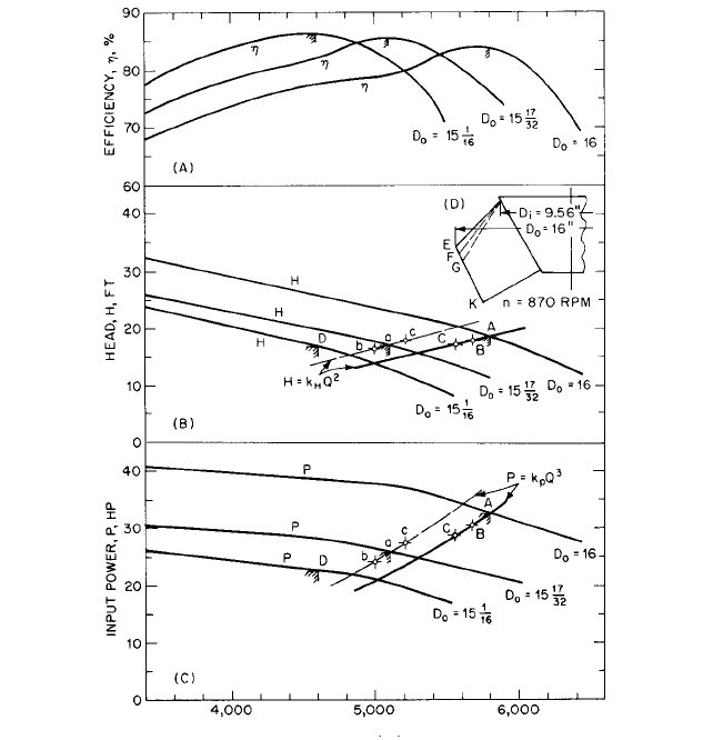
MIXED-FLOW IMPELLERS
Diameter reduction of mixed-flow impellers is usually done by cut-
ting a maximum at the outside diameter D
0
and little or nothing at the inside diameter
D
i
, as shown in Figure 16. Stepanoff
14
recommends that the calculations be based on the
average diameter D
av
(D
i
D
0
)/2 or estimated from the blade-length ratio FK/EK or
GK/EK in Figure 16d. Figure 16 shows a portion of the characteristics of a mixed-flow
impeller on which two cuts were made as in Figure 16b. The calculations were made by
Eqs. 14 using the mean diameter
instead of the outside diameter in each case.The predictions and test results are shown in
Figure 16 and Table 6. It is clear that the actual change in the characteristics far exceeded
D
m
21D
2
o
D
2
i
2>2
1
8
1
8
D¿ D1Q¿>Q2H¿ H1Q¿>Q2
2
P¿ P1Q¿>Q2
3
D¿ D2H¿>HQ¿ Q2H¿>H P¿ P1H¿>H2
3>2
5
16
H k
H
Q
2
and P k
p
Q
3
5
16

2.340
TABLE 4 Predicted characteristics at different impeller diameters on a radial-flow pump
Test values Predicted from Predicted from
D 16 in (41.4 cm) D 15 in (88.4 cm)
D,in Q, gpm H, ft P,hp n
s
n
s
DQ¿, gpm H¿, ft P¿, hp Q¿, gpm H¿ ft P¿, hp
(cm) (l/s) (m) (kW) (
s
)(
s
D) (l/s) (m) (kW) (l/s) (m) (kW)
16 4000 224.4 270.4 1953 31,860 . . . . . . . . . 3888 227.3 272.2
(41.4) (252) (68.4) (201.6) (0.7146) (29.54) (245) (69.3) (203.0)
2.93% 1.29% 0.68%
error
a
error
a
error
a
15 3600 195.4 217.0 2055 31,080 3709 192.9 215.5 . . . . . . . . .
(38.4) (227.1) (59.6) (161.8) (0.7519) (28.87) (234) (58.8) (160.7)
3.02% 1.28% 0.69%
error
a
error
a
error
a
14 3200 163.6 167.2 2214 31,000 3433 165.3 170.9 3332 167.4 172.1
(35.6) (201.9) (49.9) (124.7) (0.8101) (28.84) (217) (50.4) (127.4) (210.2) (51.0) (128.3)
7.28% 1.03% 2.33% 4.13% 2.33% 2.93%
error
a
error
a
error
a
error
a
error
a
error
a
a
Error in predicting best efficiency point.
1
8
5
16
1
8
5
16
2.3.1 CENTRIFUGAL PUMPS: GENERAL PERFORMANCE CHARACTERISTICS 2.341
the predicted values. Except for the use of the mean diameters, the procedure was essen-
tially the same as that described for Figure 13, and all points and curves are similarly
labeled. The corrections given in Figure 14 would have made very little difference in the
computed diameter reductions, and those of Figure 15 were not applicable to impellers
having specific speeds greater than n
s
2000 (0.73). In this case, the product n
s
D
m
did not
remain constant and the maximum efficiency increased as D
m
was reduced. Although the
FLOW RATE Q, GPM
(0.715)
(0.752)
(0.810)
FIGURE 13A through C Diameter reduction of radial-flow impeller (gpm 0.06309 = l/s). D is measured in
inches (centimeters).

2.342 CHAPTER TWO
FIGURE 14 Corrections for calculated impeller diameter reductions (Reference 12)
FIGURE 15 Corrections for calculated impeller diameter reductions (Reference 13). (
s
n
s
/2733)
TABLE 5 Impeller diameter corrections
D before cutting in 16.3125 16.3125
D¿ predicted by Eqs. (14) in 15.125 14.000
D¿ corrected by Figure 14 in 15.25
a
14.26
b
D¿ corrected by Figure 15 in 15.60
c
14.93
d
a
D¿/D 15.125/16.3125 0.927; by Figure 14, corrected D¿/D 0.935. Corrected D¿
(0.935)(16.3125) 15.25 in.
b
D¿/D 14.000/16.3125 0858; by Figure 14, corrected D¿/D 0.874. Corrected D¿
(0.874)(16.3125) 14.26 in.
c
D D¿ 16.3125
—
15.125 1.1875; by Figure 15, K 0.6 at n
s
1,953. Corrected D D¿
(0.6)(1.1875) 0.7125 and corrected D¿ 16.3125
—
0.7125 15.60 in.
d
D D¿ 16.3125
—
14.000 2.3125; by Figure 15, K 0.6 at n
s
1,953. Corrected D D¿
(0.6)(2.3125) 1.3875 and corrected D¿ 16.3125
—
1.3875 14.93 in.
changes in diameter were small, the area of blade removed was rather large for each cut.
The second cut eliminated most of the blade overlap.
The characteristics of mixed-flow impellers can be changed by cutting, but very small
cuts may produce a significant effect. The impellers of propeller pumps are not usually
subject to diameter reduction.
Shaping Blade Tips If the discharge tips of the impeller blades are thick, performance
usually can be improved by filing over a sufficient length of blade to produce a long, grad-
ual taper. Chamfering, or rounding, the discharge tips may increase the losses and should
never be done. Reducing the impeller diameter frequently increases the tip thickness.
2.3.1 CENTRIFUGAL PUMPS: GENERAL PERFORMANCE CHARACTERISTICS 2.343
FLOW RATE Q, GPM
FIGURE 16A through C Diameter reduction of mixed-flow impeller (ft 0.3048 = m; in 2.540 = cm; gpm
0.06309 = l/s; hp 0.7457 = kW)
OVERFILING
This is shown at B in Figure 17, and the unfiled blade is shown at A. Usu-
ally there is little or no increase in the blade spacing d before and d
F
after filing, so the
discharge area is practically unchanged. Experience indicates that any change in the
angle b
2
due to overfiling usually produces a negligible change in performance.
UNDERFILING This is shown at C in Figure 17. If properly done, underfiling will increase
the blade spacing from d to d
f
and hence the discharge area, which lowers the average
meridional velocity c
m2
, at any given flow rate Q. The angle b
2
usually is increased slightly.
Figure 18A and Eq. 6 show that the head and consequently the power increase at the same
flow rate.The maximum efficiency usually is improved and may be moved to a higher flow
rate. At the same head, Figure 18B shows that both c
m2
and the flow rate will increase.
The change both in the area and in C
m2
may increase the flow rate by as much as 10%.
Table 7 shows the results of tests before and after underfiling the impeller blades of nine
different pumps. In general, they confirm the foregoing predictions based on changes in
area and in the velocity triangles.

2.344
TABLE 6 Predicted characteristics at different impeller diameters on a mixed-flow pump
Predicted from Predicted from
D 16.00 (40.64 cm), D 15.53 (39.45 cm),
Test values D
m
13.17 (33.45 cm) D
m
12.89 (32.74 cm)
D, in D
m
, in Q, gpm H, ft P, hp Q¿, gpm H¿, ft P¿, hp Q¿, gpm H¿, ft P¿, bp
(cm) (cm) (l/s) (m) (kW) n
s
n
s
D
m
(l/s) (m) (kW) (l/s) (m) (kW)
16 13.17 5800 18.6 32.5 7385 97,300 . . . . . . . . . 5210 17.9 27.4
(40.64) (33.45) (365.9) (5.67) (24.2) (2.702) (90.39) (329) (5.46) (20.4)
11.3% 3.91% 18.6%
error error error
15 12.89 5100 17.1 25.7 7385 95,200 5680 17.8 30.4
(39.45) (32.74) (321.8) (5.21) (19.2) (2.702) (88.47) (358.4) (5.43) (22.7)
10.2% 4.50% 15.5%
error
a
error
a
error
a
15 12.62 4600 16.8 22.6 7100 89,600 5560 17.1 28.6 5000 16.4 24.1
(38.26) (32.05) (290.2) (5.12) (17.1) (2.598) (83.26) (350.8) (5.21) (21.6) (315.5) (5.00) (18.2)
17.3% 1.75% 21.0% 8.00% 2.44% 6.22%
error
a
error
a
error
a
error
a
error
a
error
a
a
Error in predicting best efficiency point.
1
16
17
32