Protection Application Handbook (англ. яз.)
Подождите немного. Документ загружается.


RELATIVE SELECTIVE PROTECTION RELAYS
Setting of Protection
for worldwide cooperation
321
BA THS / BU Transmission Systems and Substations
LEC Support Programme
An instantaneous protection can thus, with a margin, be set high-
er than this, which means that the relay will detect faults inside
the transformer, but will never reach through the transformer.
Further factors to be considered at setting of instantaneous stage
for this transformer are:
- Transient overreach of current relay, i.e. overreach due to DC
component in fault current. This overreach can on modern relays
be of size 2-15% whereas for older electromechanical relays it
can be 10-30%. Transient overreach is defined as (1 -K)/K where
K = quotient between the operation value for symmetrical AC
component with fully developed DC component and the opera-
tion value for symmetrical AC current without DC component.
- Differences in transformer short-circuit impedance due to tap
changer step. Impedance is normally given at mid-point and can
differ + 1-2% percentage units (or even more) at end taps. (Note
that given percentage impedance is valid for the voltage at re-
spective tap).
- Maximum inrush current must be lower than selected setting.
After considering these factors the instantaneous stage is nor-
mally set to cover maximum 80% of transformer and is thus a
complement to transformer differential and Buchholz protection
for internal faults.
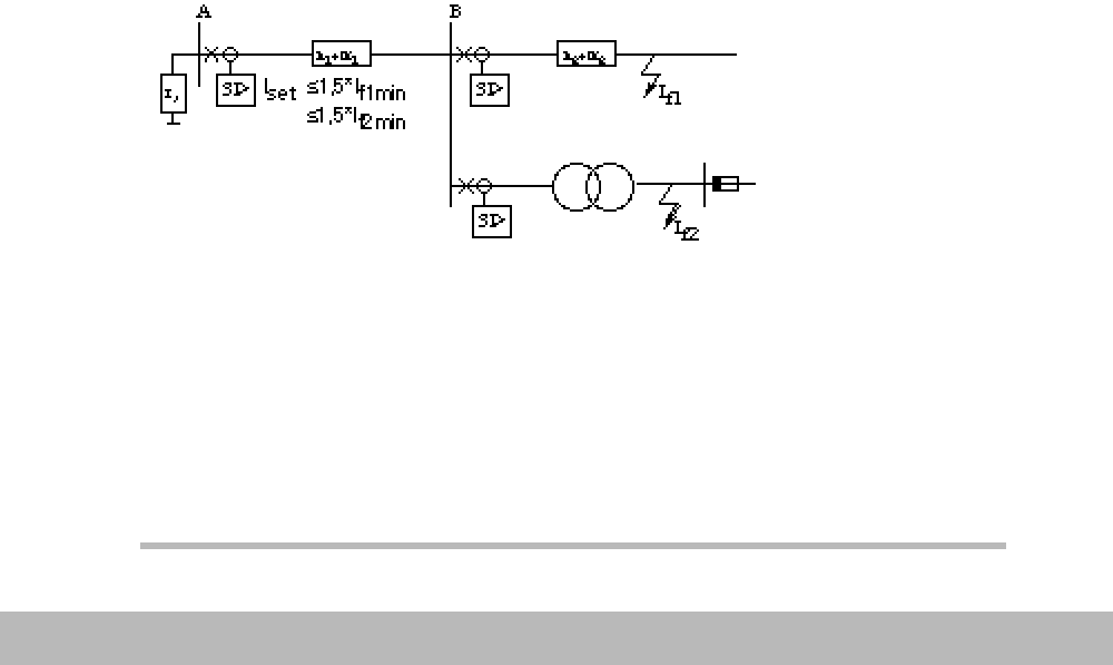
Margin to minimum fault current (Tripping requirement)
Figure 15. The minimum fault current achieved for which the overcurrent re-
lay is required to be back-up must be detected.
When setting is calculated according to above it has to be
checked that the minimum fault current, normally for a two phase
fault, is sufficient to operate the relay. A margin factor to minimum
fault current of at least 1.5 is required.

RELATIVE SELECTIVE PROTECTION RELAYS
322
BA THS / BU Transmission Systems and Substations
LEC Support Programme
Consideration must be given to the fact that two different inde-
pendent protection relays, operating on different circuit breakers,
shall be able to detect the fault. This means e.g. that a fault at the
far end of a distribution line or on the low voltage side of a trans-
former in the remote station must be detected under minimum
fault current conditions.
This is often difficult to achieve, and compromises on selectivity
under maximum conditions might be necessary to ensure suffi-
cient sensitivity under minimum condition.
The tripping requirement must always have priority, i.e. lack of se-
lectivity is preferred compared to failure to trip.
Margin to equipment capacity
At primary short circuits the plant is exposed to heavy mechani-
cal and thermal stresses. The mechanical stresses cannot be in-
fluenced by the protection relays but the thermal stresses are
dependent upon fault time (time to fault clearance). Following ex-
pression can be used
I
k2
• t
k
= I
12
where
I
k
= Acceptable short circuit current for time tk
I
1
= short circuit capacity for time 1 sec.
Above formula can be used to calculate the thermal capacity for
fault times in range 0.5 - 5 sec.
When setting short circuit protection relays, back-up protection
tripping should be achieved before the thermal capacity of an ob-
ject is exceeded.
Earth-fault protection
The earth-fault protection measures the residual sum of the
three-phase currents and will thus not measure any current dur-
ing healthy condition. The setting of earth-fault protection relays
can thus be made independent of load currents. The current set-
tings will be dependent of the power system earthing.
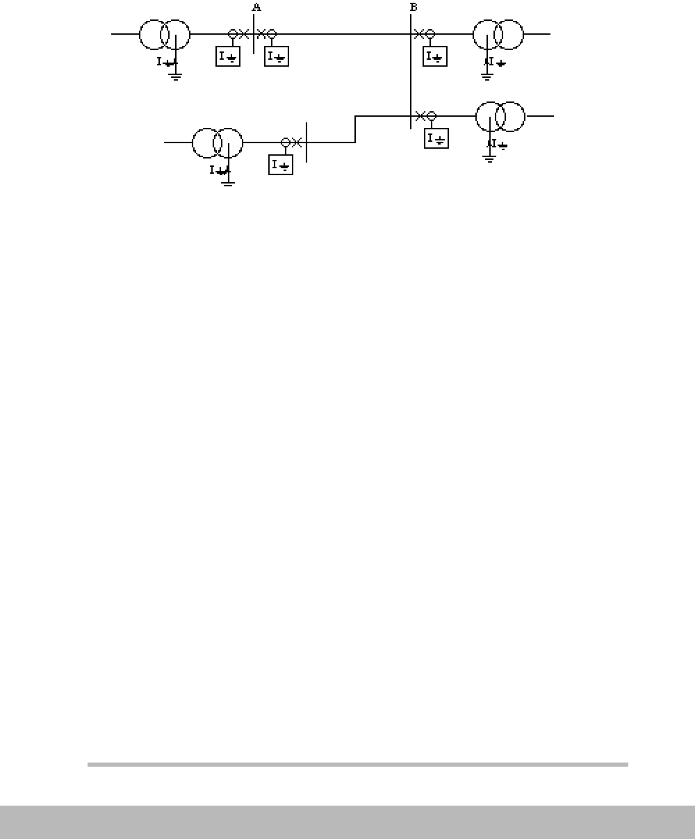
Solidly earthed system
In a solidly earthed system contributions to fault current is
achieved from all system earthings, i.e. normally all transformer
neutrals. Earth fault currents are normally not transferred to other
voltage levels as earth-fault currents, except when autotrans-
formers are involved.

RELATIVE SELECTIVE PROTECTION RELAYS
Setting of Protection
for worldwide cooperation
323
BA THS / BU Transmission Systems and Substations
LEC Support Programme
Directional earth-fault relays are often required to give a possibil-
ity of achieving selectivity, but it can also be possible by using
protection relays with inverse-time characteristic and same set-
ting on all objects. The faulty objects is then tripped first since
fault current always is bigger on faulty object than on the object
with the highest infeed.
Figure 16. The earth fault protection relays in a solidly earthed system.
Protection operation level is dependent on practises in each
country, - on requirement from telecom-systems - on requirement
from personnel safety (due to voltage on tower structures at
faults) etc. For voltages 100-400 kV the earth-fault currents re-
quired to be detected can be in range 100-400 A whereas on low-
er voltages the value can be as low as 50-100 A.
When power lines are not transposed the occurring unbalance
current in the system will cause problems for sensitive earth-fault
protection relays. Operating current should then be increased to
up to 70% of maximum load.
Low impedance earthed system
For low-ohmic earthed systems, where system earthing is a
zig-zag transformer with or without a low-ohmic resistor, or a
low-ohmic resistor directly in a transformer neutral, the fault cur-
rent is generated from one point only and selectivity can be
achieved by grading the time settings of the earth-fault protection
relays at different locations.
Required current setting is normally 10 - 30% of achieved maxi-
mum earth-fault currents and the same for all protection relays in
the system. A small increase of protection settings, moving to-

RELATIVE SELECTIVE PROTECTION RELAYS
324
BA THS / BU Transmission Systems and Substations
LEC Support Programme
wards the source should be used to prevent random operation
due to differences in CT's and protection relays.
As a complement a stand-by earth-fault protection can be includ-
ed in the zig-zag transformer neutral. This protection is set on the
continuous thermal capacity current of the zig-zag transformer
and on a very long time (20-30 sec.)
High-ohmic earthed system
High-ohmic earthed systems are earthed in the same way as
low-ohmic earthed systems but with a high-ohmic resistor in the
neutral. The resistor is normally selected to give fault currents of
5 - 25 A.
Current relays with definite time delay are used and selectivity is
achieved by time-grading. Required current setting is normally 10
- 30% of maximum earth-fault current and close to equal for all
relays throughout the system. Directional earth-fault relays, mea-
suring the resistive component only, are often required due to in-
feed of capacitive earth-fault current from healthy objects.
Time settings
The required time interval, for time selective protection relays,
with definite time delay, is decided as follows:
When inverse time-lag relays are used the situation is slightly
changed. The required time setting will then be:
Relay A Operating time measuring relay A
+ Time lag relay operating time A
+ Auxiliary relay operating time A
+ Breaker A total breaking time
= Total fault clearance time for A
Relay B Total fault clearance time for A
- Time lag relay operating time B
+ Reset time measuring relay B
+ Retardation (overshoot) time, time lag relay B
- Impulse time for auxiliary relay B
+ Margin between A and B
= Required setting protection B

RELATIVE SELECTIVE PROTECTION RELAYS
Setting of Protection
for worldwide cooperation
325
BA THS / BU Transmission Systems and Substations
LEC Support Programme
For selectivity between inverse time-lag relays or fuses the selec-
tivity has to be checked for all fault currents.
Special consideration has to be given maximum fault current con-
ditions since tripping times then are shortest
Time margin between A and B should, for short circuit protection
relays, be 100 -150 ms to allow for errors and not risk any malop-
eration. For earth fault protection relays, where CT's are residu-
ally connected, the time margin should be increased to 150-200
ms due to the additional error caused by the summation of cur-
rent transformers in the three phases.
Overload protection
Thermal overload protection relays are often used as protection
of objects such as motors, small transformers, generators and re-
actors with relatively large time constants and risk of overheating
due to overload. Overload protection relays should be included in
the selectivity plan and are set to provide protection against ther-
mal damage of protected object.
Proposed settings: Overload protection relays are set on 1.02 x
Object rated current (complying to 1.04*Thermal content) and set
with a thermal time constant not exceeding the thermal time con-
stant of the protected object. If no temperature compensation is
Relay A Operating time for time-lag overcurrent relay (at maxi-
mum fault current for which A and B relays must be
selective)
+ Auxiliary relay operating time A
+ Breaker A total breaking time
= Total fault clearance time for A
Relay B Total fault clearance time for A
- Retardation (overshoot) time for time-lag overcurrent
relay at B at maximum fault current for which relays
needs to be selective plus possible load from other
objects)
- Impulse time for auxiliary relay B
+ Margin between A and B
= Required setting protection B

RELATIVE SELECTIVE PROTECTION RELAYS
326
BA THS / BU Transmission Systems and Substations
LEC Support Programme
provided, object time constant for highest surrounding tempera-
ture must be considered.
Note: If shunt capacitors are included in e.g. a motor circuit, the
contribution of these capacitors must be considered when calcu-
lating the nominal load current.
Voltage protection
Different types of voltage protection relays are used in a power
system.
Neutral point voltage protection is used as a back-up protection
for earth faults both on solidly, low-ohmic and high-ohmic earthed
systems. Open delta winding on voltage transformer is normally
selected to give 110 V secondary at a solid earth-fault. This is
achieved with a secondary VT voltage of 110 V for solidly earthed
system and 110/3 for high-ohmic and unearthed systems.
Normally a setting of 20V is used. When lower settings are used,
e.g. for generators (normally about 5 V) or SVS (Static Var Sys-
tem), a third harmonic filter is mostly necessary to prevent mal-
operation due to the in normal service occurring third harmonic
component.
Neutral point voltage protection cannot discriminate where on a
power system voltage the fault occurs and must thus be given a
time delay to allow earth-fault current protection relays to trip first.
Undervoltage protection relays can be used for different applica-
tions
As undervoltage protection relays for busbars with synchronous
and/or asynchronous motors. Synchronous motors can at under-
voltage quickly come out of synchronism and must thus quickly
be disconnected. Asynchronous motors will, after an undervolt-
age of longer duration, at voltage recovery require new starting
currents which, if many motors are connected to the same bus-
bar, can cause operation of current protection relays on higher
level in the selectivity plan. Thus asynchronous motors need to
be disconnected when long voltage drops occur.
Suitable settings
t = 0.15 s for synchronous motors
t = 0.4 s for asynchronous motors

SELECTIVITY PLAN
Setting of Protection
for worldwide cooperation
327
BA THS / BU Transmission Systems and Substations
LEC Support Programme
As undervoltage protection on busbars with high priority loads,
where voltage protection will separate power systems and allow
high priority network to be undisturbed.
Suitable settings
U = 80% t = 0.4 s
Undervoltage protection relays need not be included in the selec-
tivity plan but must of course be coordinated. Firstly, with the sys-
tem voltage profile obtained in the voltage drop calculations, to
prevent tripping under conditions where the service can be main-
tained. Secondly, to obtain a load shedding or sectionalizing in an
orderly manner.
No-voltage (Zero voltage) automatic is used to open the circuit
breakers at loss of voltage and thus prepare for system restora-
tion after a disturbance. This automatic is set to operate after all
other protection relays.
Suitable setting:
U = 40% - 50%
and the protection must thus be given a time delay to allow
earth-fault current protection relays to trip first.
4. SELECTIVITY PLAN
Preparation
Necessary informations when starting to prepare the selectivity
plan are
- System diagram is needed to follow the distribution of fault and
load currents.
- Maximum short-circuit currents are needed to check the rating
of the relays. (It is very much needed to check the stability of ab-
solute selective protection relays, e.g. differential protection re-
lays.)
- Minimum short-circuit currents are needed to ensure that no
current relay is set too high to operate (tripping requirement) un-
der minimum fault condition.
- Maximum service currents are needed to check that no protec-
tion relays trip erroneously during permissible service conditions.

SELECTIVITY PLAN
328
BA THS / BU Transmission Systems and Substations
LEC Support Programme
The maximum service currents and their order and duration for
different objects can be:
Transformers: Inrush current about 5-20 • In during the first peri-
od, decreasing 20% per period.
Motors: Starting current 1.5-8 • In lasting up to 25 seconds (dif-
fers a lot depending on type of load).
Busbars: Reacceleration current to all supplied objects of the cur-
rents (motors) after a net disturbance of short duration. Size and
duration can be obtained through voltage drop calculations.
- Relay characteristics are needed to decide upon the margins
between consecutive protection relays. The margins are influ-
enced by protective relay accuracy, setting accuracy, tempera-
ture range, auxiliary voltage variations, reset value and “point of
no return” for the relays.
- Breaker characteristics, especially the total breaking time, are
needed to calculate required margin between the consecutive
protection relays time setting.
Step by step instruction
1) Prepare yourself by assembling and calculating: single line di-
agram, system rated data, fault powers/currents plus relay block
diagram and relay characteristics on log-log paper (50 mm scale
factor). Inrush currents for transformers, start currents for motors
etc. are also assembled as indicated under 3.1 above.
If different voltage levels are involved, which is normally the case,
it's advantageous to use MVA (kVA) instead of currents in the se-
lectivity plan. After selecting MVA (kVA) setting for each relay the
setting is calculated to primary and secondary current for the ob-
ject.
Use 50 mm scale factor log-diagrams, semi-transparent, for your
selectivity plan. When only definite time protection relays are
used semi-transparent paper and relay characteristics are not
needed.
2) Start with settings of overcurrent protection relays and then
calculate settings of earth-fault protection relays. Selectivity must
be checked for faults on all objects.
3) Indicate time and MVA (kVA) scale on semi-transparent paper.
Same time scale as on relay characteristics should preferably be
used.
4) Start with the object lowest in the selectivity chain, where the
highest setting is foreseen. Calculate current and time setting, or
select time constant (on inverse type relays), for the relative se-

SELECTIVITY PLAN
Setting of Protection
for worldwide cooperation
329
BA THS / BU Transmission Systems and Substations
LEC Support Programme
lective protection required to operate first for a fault on the object
where selectivity is checked. See section 2.2 for setting calcula-
tion.
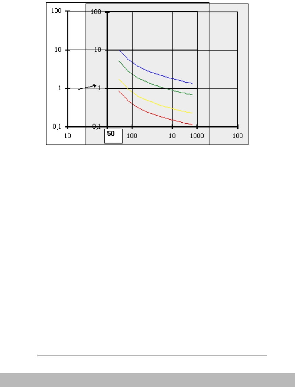
Figure 17. Set the first relay to 50 A by putting 50 A matching 1 on the relay
characteristic sheets.
5) Put the semi-transparent log-log paper over the selected relay
curve and check that 1 sec. fits to 1 sec. and that selected MVA
setting fits to 1 (set current/power) on the semi-transparent and
the relay characteristic paper respectively. Draw the selected re-
lay characteristic on the semi-transparent paper.
Example of setting 50 MVA, k = 0.05 sec.
6) Calculate required current setting on next relay to operate ac-
cording to instructions under section 2.2 and find a suitable time
setting by trying with different k values and checking time and
current margin for all fault currents. Doing this it is advantageous
to add information about maximum and minimum fault cur-
rent/power at/through different objects on the semi-transparent
log-log paper.
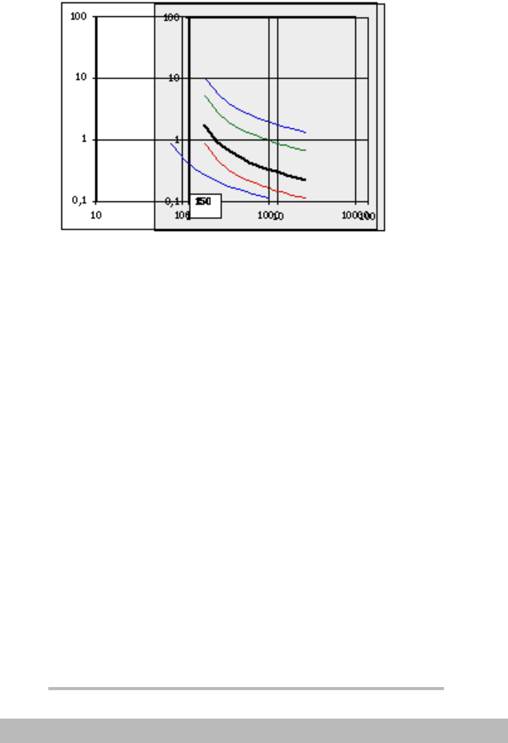
Relay setting 150 MVA k = 0.1

SELECTIVITY PLAN
330
BA THS / BU Transmission Systems and Substations
LEC Support Programme
Figure 18. Set next relay to 150 A by putting 150 A matching 1 on the relay
characteristic sheets. Draw the required curve giving sufficient time margin
for all currents achieved.
7) Repeat the procedure for all further protection relays required
to be selective.
8) Check that the back-up tripping times does not exceed thermal
capacity of the objects
9) Repeat the same procedure for earth-fault relays.
Check for faults at different locations, that short-circuit protection
relays will not give shorter tripping times and thus disturb the se-
lectivity for earth-faults. Doing this it must be remembered that an
earth-fault protection measures neutral current whereas
short-circuit protection measures phase currents.
Absolute selective protection relays in the selectivity plan
It can sometimes be advantageous to indicate instantaneous unit
protection relays in the selectivity plan to check that relative se-
lective protection relays are not interfering.
A differential protection is simple to indicate as it will operate for
certain current levels only and provide a fixed operating time of
20-40 ms.
