Protection Application Handbook (англ. яз.)
Подождите немного. Документ загружается.

INSTRUMENT TRANSFORMERS
Control System Structure
for worldwide cooperation
281
BA THS / BU Transmission Systems and Substations
LEC Support Programme
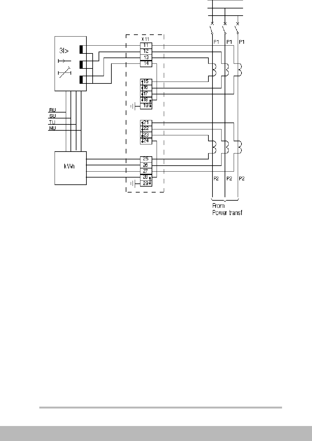
Figure 4. A terminal arrangement which allows simple reconnection of a cur-
rent transformer direction and a simple testing of each core.
2.2 VOLTAGE TRANSFORMERS
Location
The location of the voltage transformers will primary depend on
the switchgear arrangement, the protection, the metering and the
automatics connected.
Normally, voltage transformers connected to the busbars and at
the low voltage side of the transformers are satisfactory in a dis-
tribution substation.
Directional Protection on outgoing bays are then fed from the
busbar VT:s.

INSTRUMENT TRANSFORMERS
282
BA THS / BU Transmission Systems and Substations
LEC Support Programme
On the transmission voltage level the protection equipment will
normally require voltage transformers at all objects, sometimes
with exception of the HV side of power transformers.
Further, a single phase set is located at the busbars for voltage,
frequency and synchronizing purpose. This avoids complex volt-
age selection schemes.
Earthing and fusing.
The secondary circuits are fused and earthed in the VT marshal-
ling box. This will ensure that dangerous voltages will not occur.
Connection of different VT/CVT circuits should therefor be avoid-
ed to prevent equalizing currents in the secondary circuits during
primary earth faults.
The fusing can be done with diazed fuses or Miniature circuit
breakers (MCB:s). The tripping condition must be checked i.e. it
must be checked that the fuses/MCB will trip within a reasonable
time (e.g. 5 sec). This normally means that higher rated currents
than 6 A cannot be used.
Supervision
A fault can always occur even if the plant is well designed and
well constructed. When a fault occurs it’s of importance that the
fault is immediately detected and an alarm given to enable the
maintenance personal to quickly repair the fault. A fault in a me-
tering circuit will mean incorrect metering, with loss of income as
a result. A fault in a protection circuit can mean one missing or
incorrect tripping which will lead to unnecessary disconnecting of
one or several objects.
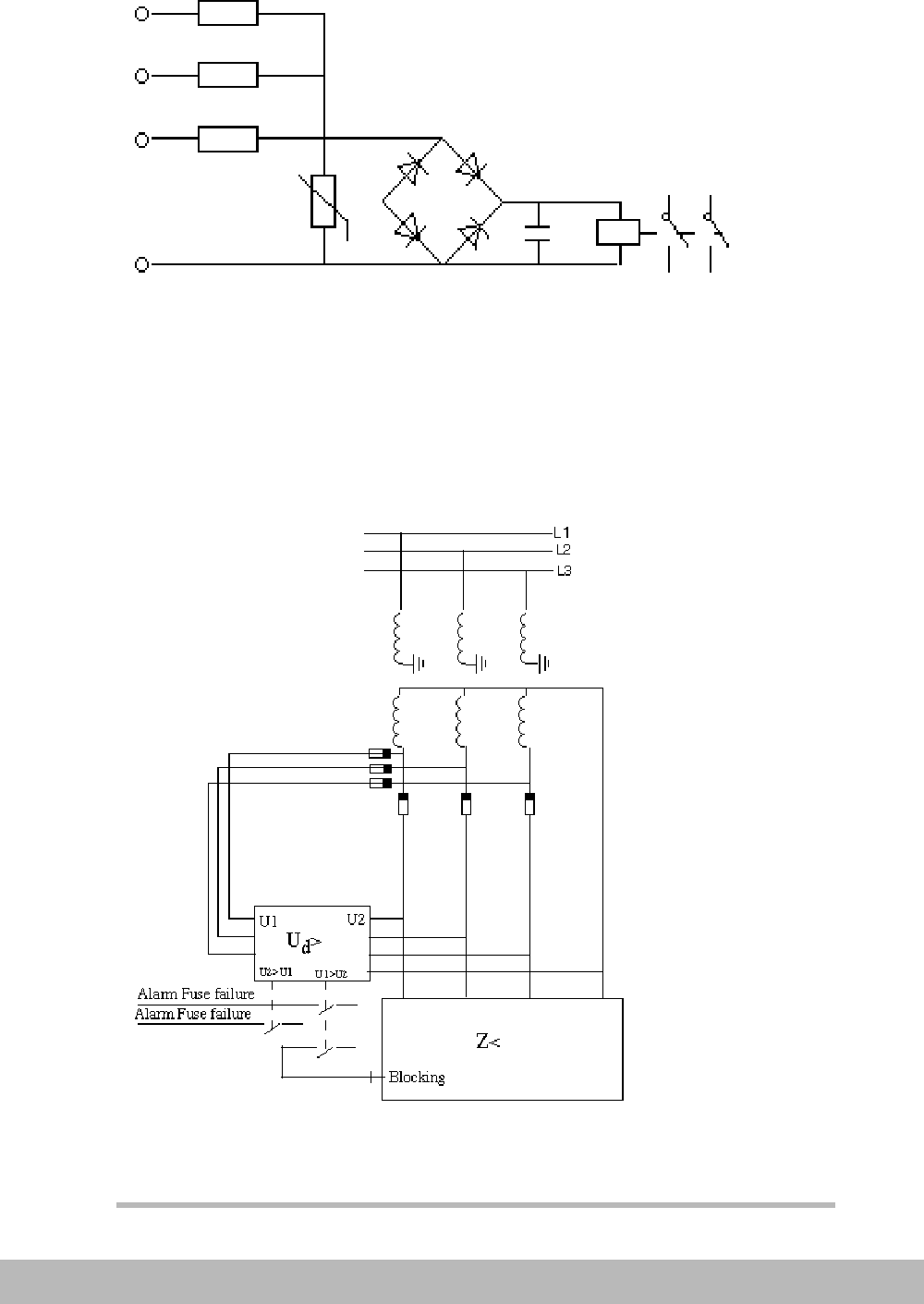
The supervision of a voltage transformer secondary circuit can
be done according to Figure 5 if the circuit supplies metering
equipment. An occurring unsymmetry between the phases will
be detected and the relay can by that detect one or two phase
fuse failure.
INSTRUMENT TRANSFORMERS
Control System Structure
for worldwide cooperation
283
BA THS / BU Transmission Systems and Substations
LEC Support Programme
Figure 5. Supervision of a voltage transformer circuit (for alarm purpose
only).
If a protection relay is supplied a supervision according to Figure
6 can be used. A differential voltage measuring is used where the
voltage of a main fuse, supplying the protection relay, and a pilot
fuse are compared. This principle will detect one, two or three
phase fuse failures.
Figure 6. Supervision of a Voltage transformer secondary circuit (for block-
ing of protection).

INSTRUMENT TRANSFORMERS
284
BA THS / BU Transmission Systems and Substations
LEC Support Programme
Another solution used to detect fuse failures in some types of Dis-
tance protection is to compare the occurrence of zero, or nega-
tive, sequence voltage with the occurrence of zero, or negative,
sequence current. If only voltage occurs the problem is a blown
fuse. If both current and voltages occur there isn’t a fuse problem
but a primary earth fault. The drawback with this principle is that
it will only detect one and two phase fuse failures. However the
normal faults on a voltage transformer circuits are to earth and in
rare cases between two phases.
If MCB:s are used an auxiliary contact can be used to give alarm.
If Distance protection relays shall be blocked a special MCB with
low instantaneous level and a very fast auxiliary contact must be
used.
Cabling
Dedicated cables shall be used for the voltage transformer sec-
ondary circuits. The cable shall be screened and earthed at both
ends to keep the disturbance voltages to low levels.
The secondary cabling must be dimensioned to:
- Ensure that fuse/MCB will operate, in a reasonable time, for a fault at the
far end of the cables.
- Keep the voltage drop, due to the burden, one level lower than the inac-
curacies in the voltage transformer.
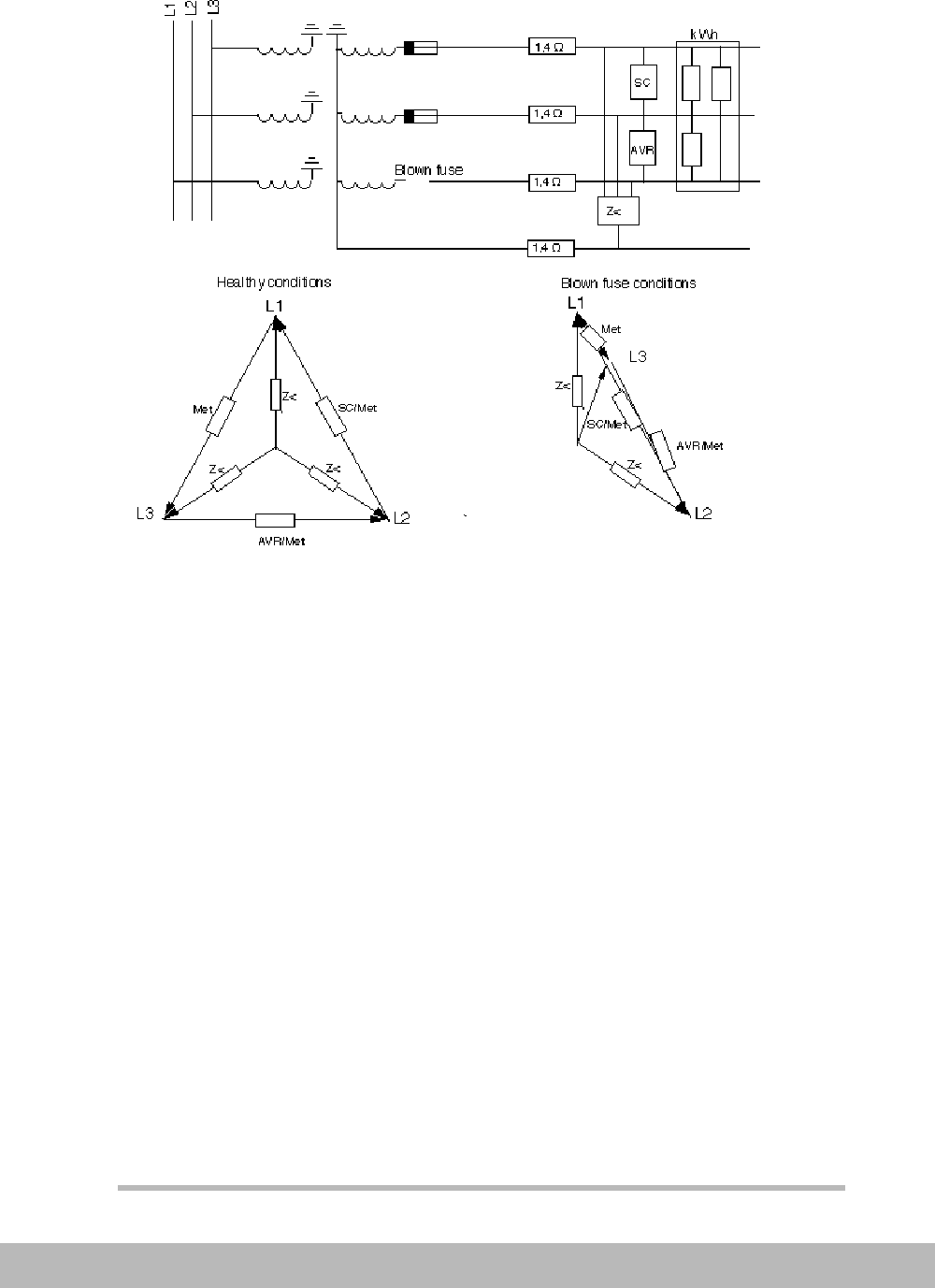
A special problem occurring in voltage transformer circuits if fus-
es are used is the risk of back-feeding a faulty phase from the
healthy phases. This phenomena occurs when phase to phase
connected load exists. The phase with the blown fuse can reach
INSTRUMENT TRANSFORMERS
Control System Structure
for worldwide cooperation
285
BA THS / BU Transmission Systems and Substations
LEC Support Programme
rather high voltage level. The level is decided by the load in the
different phases as indicated in Figure 7.
Figure 7. Back-feed of voltages to a faulty phase, when phase to phase load
exists.
2.3 AUXILIARY POWER DISTRIBUTION
The auxiliary power system has a very central role in a substa-
tion. A fault in the battery system will mean that neither control
and protection equipment nor primary equipment can fulfil their
tasks. Often a complete station or a big part of a station is influ-
ence by a main problem in the auxiliary power system.
At higher system voltages, two battery systems are mostly pro-
vided to feed the local back-up protection, in redundant protec-
tion systems.
At lower voltages this is not necessary as a protection system
with remote back-up normally is used. This means that faults can
be detected from another location as well.
INSTRUMENT TRANSFORMERS
286
BA THS / BU Transmission Systems and Substations
LEC Support Programme
The DC distribution ensures that protection relays which are pro-
viding back-up to each other (e.g. outgoing feeder and transform-
er protection) are fed from different main fuses in the battery
distribution. This will ensure that minimum possible part is tripped
at a primary fault even with a single failure in the fault clearing
chain, as in this case, in the battery system.
The super
vision of a the auxiliary power supply is of utmost im-
portance. The secured feeding of alarm circuits for DC problems
must be ensured.
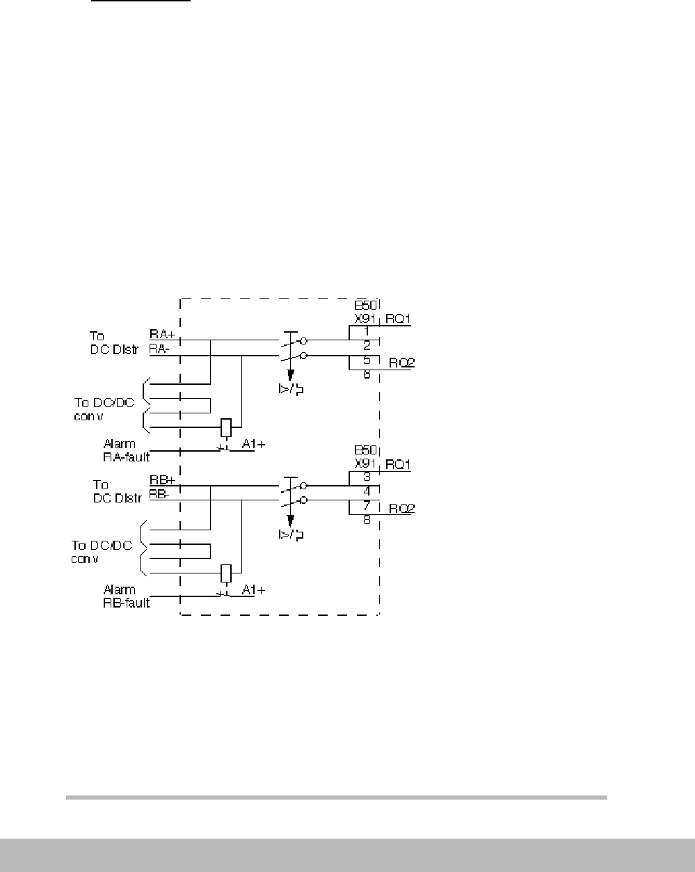
A well designed supervision of the DC supply to an object should
supervise the feeding fuse, an open circuit and a blown
fuse/MCB in the sub distribution.
An example of a DC supervision is shown in Figure 8. It’s often a
good idea to include the contacts of the DC/DC converters in the
different protection relays in the supervision, so that a common
alarm is given when DC problems anywhere in the distribution
occurs.
Figure 8. Supervision of the DC supply to a protection panel, detecting faulty
supply fuse, open circuit and DC/DC converter failures.
Supply of different equipment
Varying principles are used in the auxiliary power supply of the
equipment.
INSTRUMENT TRANSFORMERS
Control System Structure
for worldwide cooperation
287
BA THS / BU Transmission Systems and Substations
LEC Support Programme
An important principle is to limit the distribution of the auxiliary
power supply to the protection system as much as possible, and
to use only one supply to the protection of an object and the
breaker trip coil.
The limitation of the circuit distribution is done by feeding discon-
nector, earthing switch operation circuits and enabling circuits
etc. from separate supplies.
The trip coil can in a system without redundant protection be sup-
plied from the same supply as the protection relays and the trip
coil. A closing is then not possible if the voltage supply to trip isn’t
available.
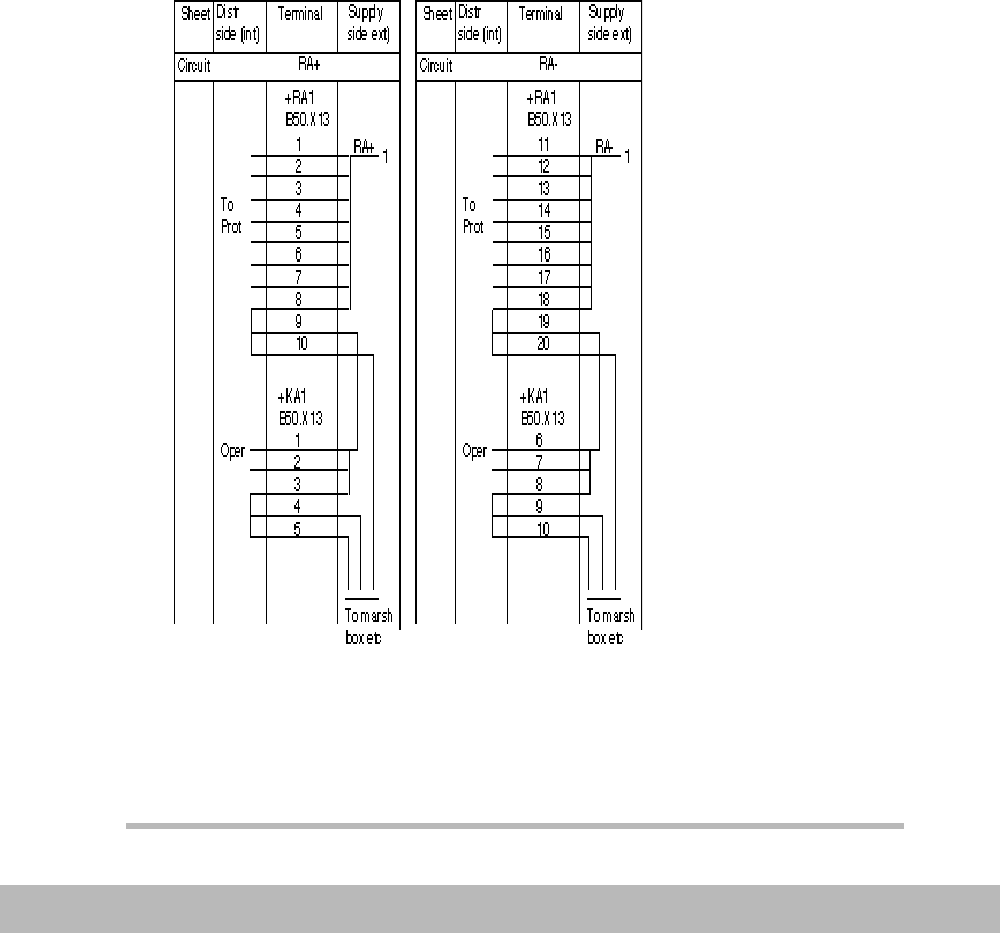
To simplify the fault finding at earth faults in the DC supply system
a structured terminal system as shown in Figure 9 can be useful.
Figure 9. A terminal arrangement, enabling a simple localization of earth
faults and a simple design of the DC distribution to different panels and box-
es.

PROTECTION AND CONTROL EQUIPMENT
288
BA THS / BU Transmission Systems and Substations
LEC Support Programme
The system includes a supply of marshalling boxes, control pan-
els (and other panels) and internal distribution from different ter-
minals, so that each circuit simply can be opened and checked
for e. g. bad insulation. The terminal numbering system utilized is
described later on.
To enable location of an earth fault, in a operation circuit, at a dis-
connector/earthing switch, with two pole operation, a resistor
shall be connected across the contact at the negative side.
3. PROTECTION AND CONTROL EQUIPMENT
3.1 DESIGN OF PANELS
The panel design and construction shall be done following a
number of general guidelines:
- The layout are to follow the layout of the primary switchgear to avoid con-
fusion.
- The panels should be clearly and visible labelled, so that objects located
in the panel is simply identified.
- The possibilities of future extensions should be kept in mind both in pan-
el design and the location in the room etc.
- Maintenance should be simplified as much as possible and the design
should minimize the risk of mistakes such as testing the wrong object or
the need of making a lot of reconnections, to enable testing.
- Two object per panel, should be avoided but must be done out of cost
reason. The belongings of the object shall then clearly be labelled both
on front and inside the panel.
Terminals
The terminals are small but important components in a substa-
tion. They should have possibility to simple connect and discon-
nect measuring wires with a clearly visible indication.
A maximum of two cores are to be connected at each side of the
terminal and a mixture of single core and stranded wires should
be avoided.
At terminal numbering a clear structure should be used to im-
prove the total quality. The design engineer will by that know

PROTECTION AND CONTROL EQUIPMENT
Control System Structure
for worldwide cooperation
289
BA THS / BU Transmission Systems and Substations
LEC Support Programme
which terminal group to use for different types of circuits.
Different circuits in the panel can simply be separated. The work-
shop testing and the site commissioning personnel will from the
numbering see what circuit type they are working with e.g. they
can simple differ a current circuit from a auxiliary supply circuit.
The terminal numbering system used by ABB Substations AB is
shown in Appendix 1.
The system used enables a clear separation of main and back-up
protection and gives an indication of interface and trip circuits
which is of importance for the service and maintenance.
The system is also made for connection of cables. Cable cores
are simple to erect as the connection of the different cores is in
the same group. Extra terminals for future use can also simply be
added with a prepared and correct number.
Trip circuit design
The trip circuits are together with the DC supply key parts of the
fault clearance chain.
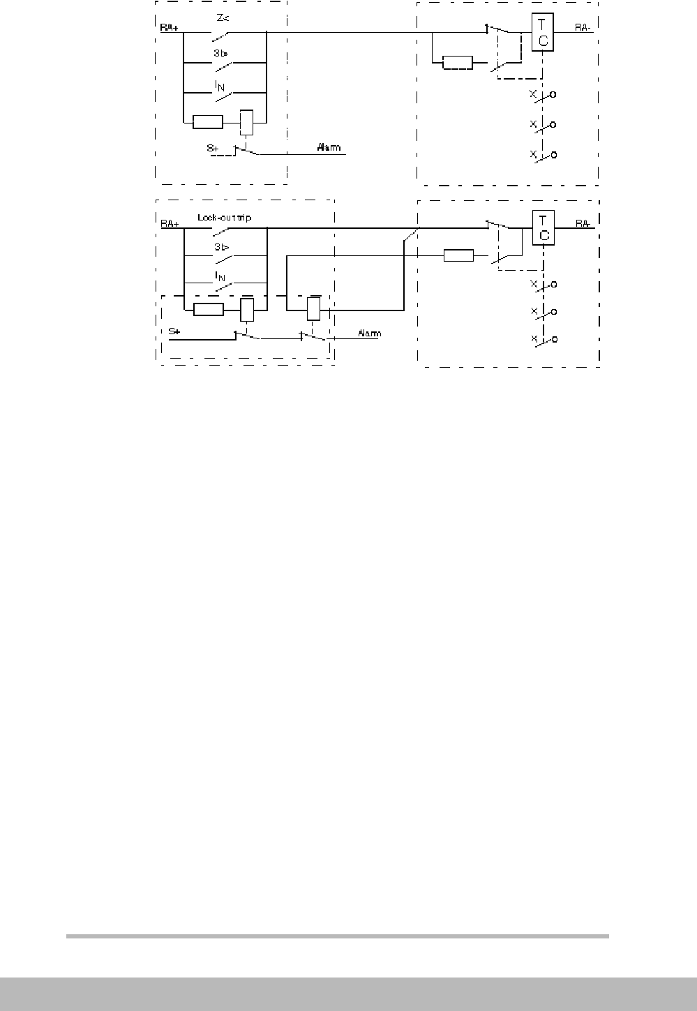
Trip circuit supervision can be used to improve the dependability
of the circuit. The circuit from the relay panel to the circuit break-
er, including the auxiliary contact of the breaker is supervised by
a small current (1-20 mA), fed through the circuit. Through a spe-
cial circuit, with a resistor and an auxiliary contact at the breaker,
the circuit can be supervised also when the breaker is open.
A double supervision where a current measuring relay is con-
nected both in the breaker circuit and across the relay can be
used when lock-out trip relays are used.
PROTECTION AND CONTROL EQUIPMENT
290
BA THS / BU Transmission Systems and Substations
LEC Support Programme
The arrangement of a trip circuit supervision is shown in Figure
10.
Figure 10. Arrangement of a trip circuit supervision.a) Single supervision,
b) Double supervision (with lock-out trip relays).
The trip coils of the circuit breaker normally have a power need
of 200-300W. A common requirement is that the contacts of the
trip relays are capable of breaking the current to the trip coils
even though there is an auxiliary contact in the breaker doing this.
This contact will however not operate at a breaker failure and
heavy duty contacts are therefor advantageous.
Busbar protection trip circuits.
Trip arrangements for busbar protection relays can be done in dif-
ferent ways. The bus-principle as shown in Figure 11 is preferred,
as it gives a simple and clear technical solution, where Breaker
